8. Computer controlled machining
Download files:
3D model of Camel head
Vector files
Note (see Individual assignment) I have made adjustment to the Slicer file, where I have changed the big parts from 4 to 3, to better assembly and use less materials.
Group Assignment
Objective:
Test runout, alignment, speeds, feeds, and toolpaths for your machine.
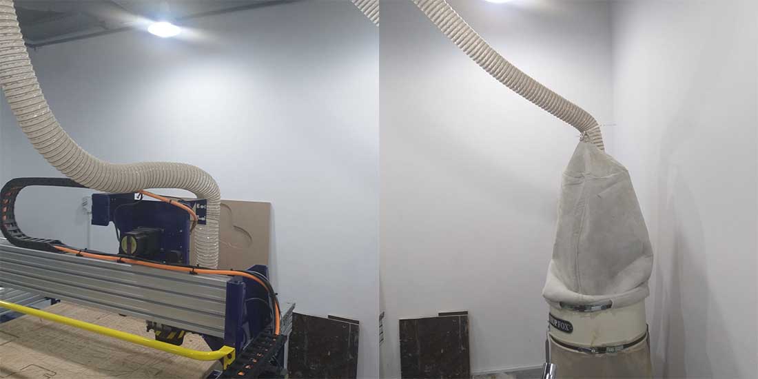
Machines used:

Dust collector
Software used:
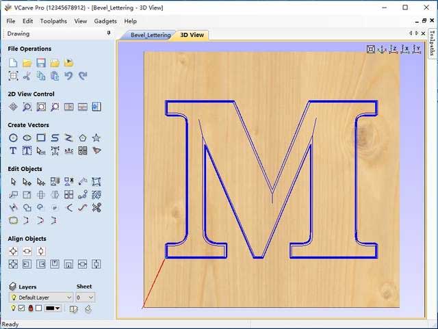
Vcarve pro; a software that make designs and generate gcodes to CNC machines.
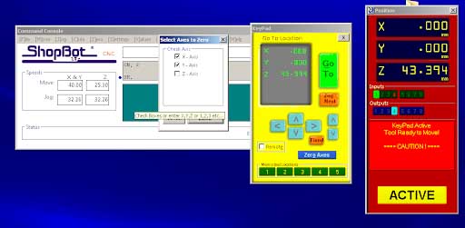
ShopBot Control Software; the program that controls the CNC machines.
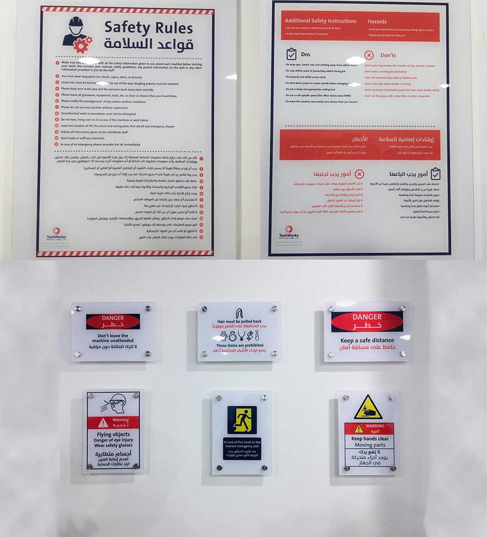
Safety and warnings:
The most important things to do are:
- Always remain with the machine while it is running, and be ready to hit the assigned key to pause the file, or the stop button to stop the machine in case of an emergency.
- Wear protective goggles.
- Wear earplugs.
- Wear respirators.
- Keep your distance from the machine while operating.
- When changing the endmill, Disengage the spindle.
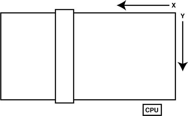
About the machine:
The size of the bed of that ShopBot is 4 x 8 feet (or 48 x 96 inches)(2440x1220mm), the exact size of stander plywood or MDF sheet.
1220mm of travel on the X axis
2440mm travel feet on the y-axis
152mm Z-axis travel (with one-inch cutter placed)
Collet size ER25 for cutters
The machine axis as shown in the picture below.
Machine specs (Metric Units):
| XY Move Speed | (with full cutting force) Variable, max. 15.24m/min. |
| Z Move Speed | (with full cutting force) Variable, max. 9.14m/min. |
| Step Resolution | 0.0127mm |
| Positional Accuracy (no load) | +/- 0.076mm |
| Linear Cutting Force | Approximately 68 Kg |
| X,Y and Z Axis Drive System | Rack and Pinion |
General rules:
Chipload:
You can download an application called FSWizard Machinist Calculator on your phone or use it on a browser.
You can choose metric system or imperial system to calculate the chipload.
Or you can calculate manually:
Chip load: ~ 0.001-0.010"
     feed rate (inches per minute) / (RPM x number of flutes)
Cut depth: ~ tool diameter
Step-over: ~ tool diameter/2
Know you chipload is right:
Too high chipload will cause poor edge finish, and transfer cutting load or thrust to the part, possibly causing it to move. Characteristic loud sound when cutting.
Too low chipload,the chip is too small, heat is transferred to the cutting tool causing premature bit failure. Characteristic sharp noise when cutting.
Material placing/ Design rules:
- Put a safe distance from the edges around 2-3cm, to make sure that the bits don’t hit holding screws.
- Make a distance between the cutting pieces around 2-3cm also.
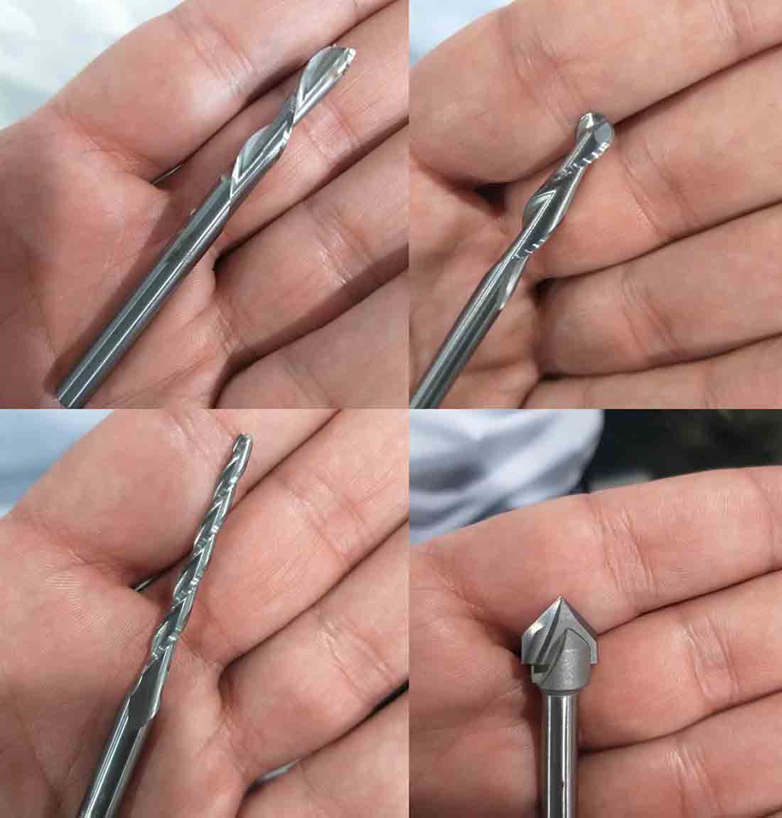
Bits:
The most common types of bits are:
- V-groove bits.
- End mill bits (also known as spiral up-cut bits), and down-cut bits
- Ball-nose bits, and also it comes with conical shape.
Set Work origin points:
By putting the Z-zero Plate bellow the spindle, then send the command from the ShopBot control software to zero the Z axis.
Fixing The Work Piece
The machine has MDF sacrifice board fixed on bed. If the spindle moves in the X axis and Y axis, it will move the work piece with it too, to make sure that won’t happen, we fixate the work piece on and sacrifice board.
And if the work piece is misaligned to the machine axes, the boarder gap will compensate misalignment and cuts will be inside work piece.
Vcarve:
From the Vectric/ Vcarve site from tutorials page we can see a lot of tutorials like 2D toolpaths, 2.5D toolpaths, and 3D toolpaths.
The main toolpaths are:
-
Profile toolpath:a 2d cut into the material, following a closed path — the result will be a cut-out piece and a cut in the stock material and may be either inside (the path will define the shape left in the stock material) or outside (the profile will define the shape cut out of the stock material). The depth parameter specifies the depth of cut into the material and should be negative.
-
Pocket toolpath: removes material from the interior of a path down to the specified depth. Note, that this is limited by bit geometry, so square corners will be rounded, matching the radius of the cutting bit, it may be that for small paths the bit will not fit w/in the path, so no cut will be made.
-
Engrave toolpath: for engraving bit like V-bits that come with variant angles.
Test cuts:
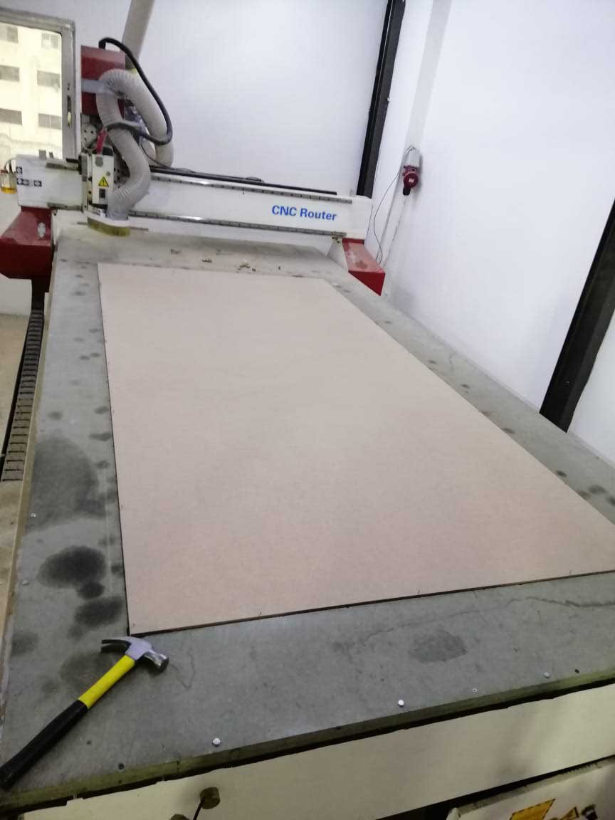
We used 17.0 mm latte sandwich uncovered wood to make the tests. Stock was measure using a caliper and the actual size was 17.2 mm. The actual size should be used in machine software. Step-by-step guide for working on VCarve Pro is provided in week assignment section.
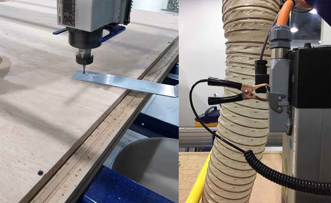
Results:
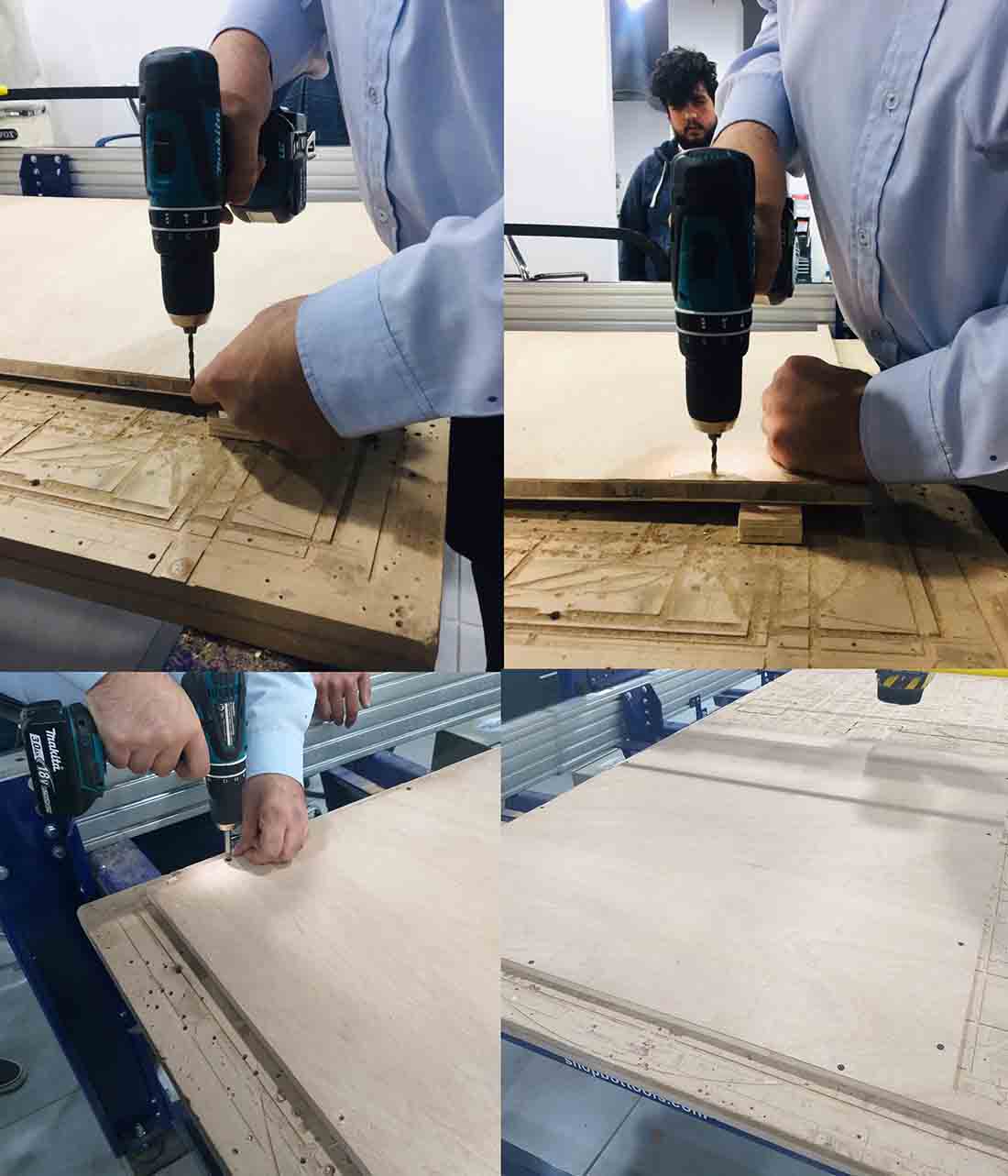
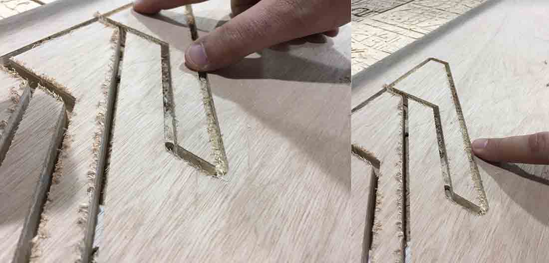
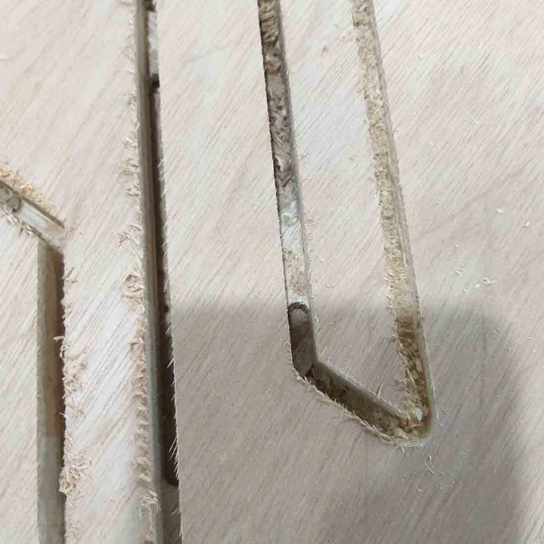
The left picture shows the cut with the up-cut endmill, where the result shows chips coming from the surface of the work piece.
Unlike the right picture shows clean cut on the surface.
In the next picture it shows the taps that holds down the finished pieces.
Individual assignment:
Objective:
Make (design, mill, and assemble) something big.
My objective:
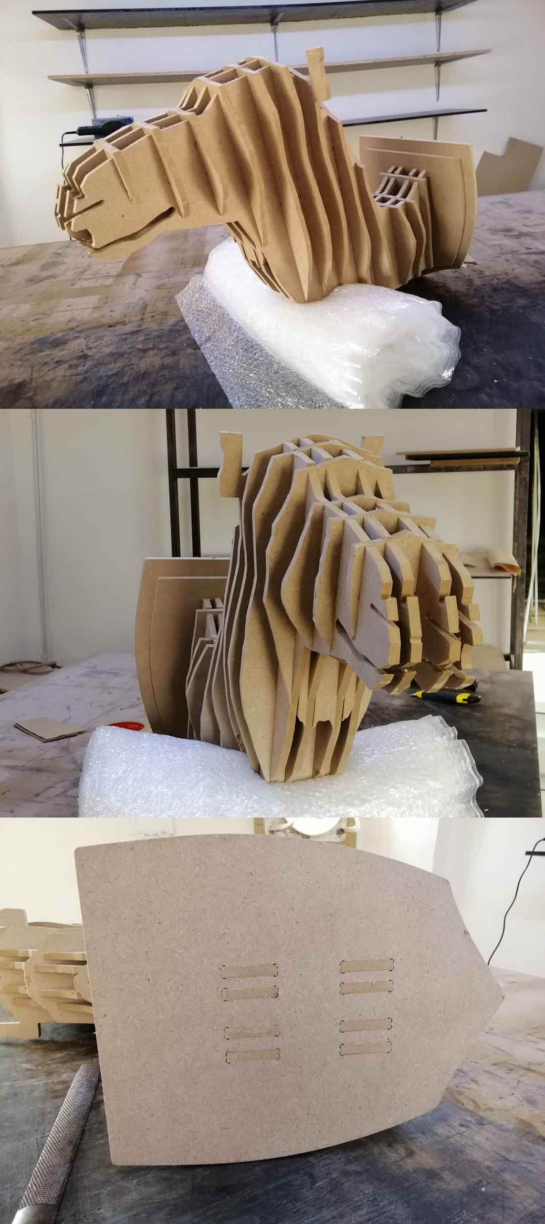
I want to make a camel (animal) puzzle CNC from scratch.
Machine used:
Chinese CNC Router.
Programs Used:
Artcam 2017; ; a software that make designs and generate gcodes to CNC machines.
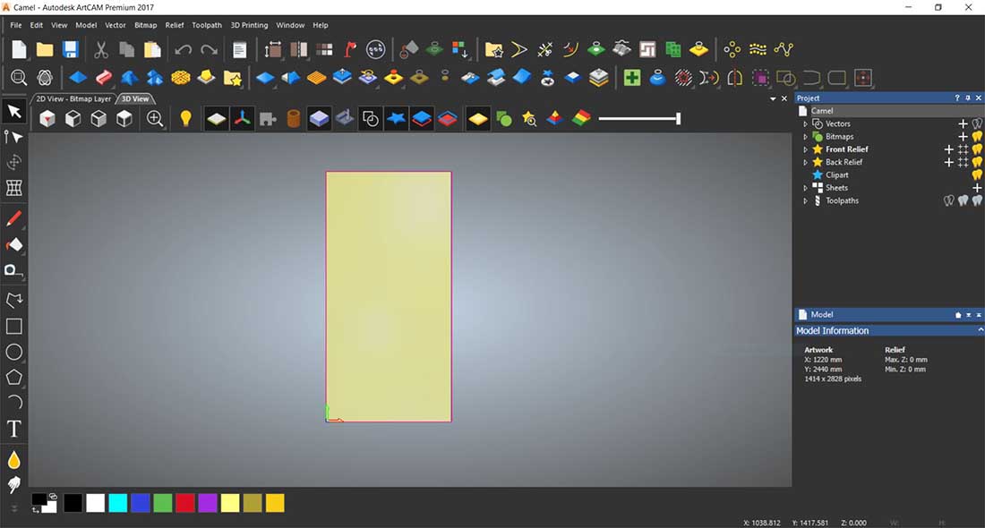
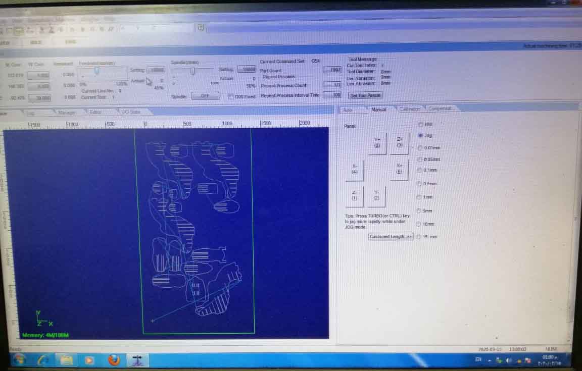
NC studio; the program that controls the CNC machines.
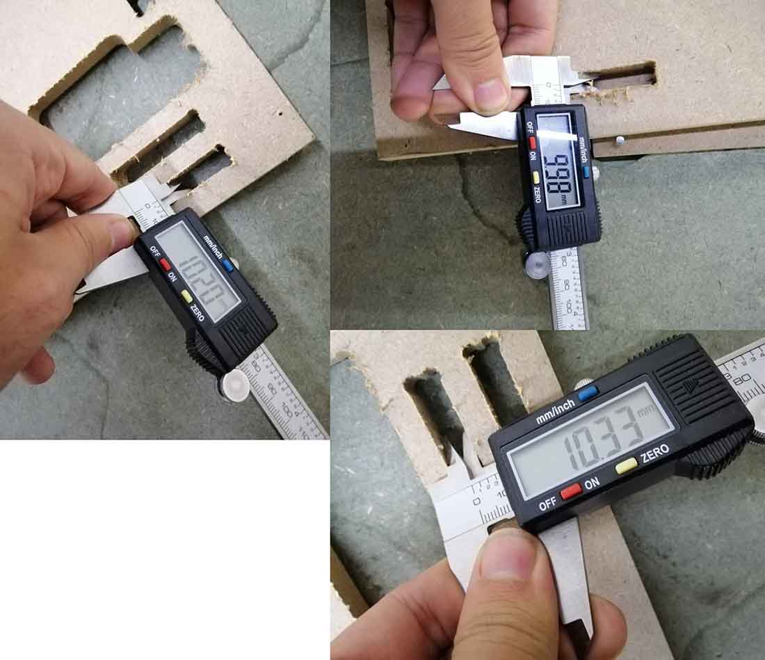
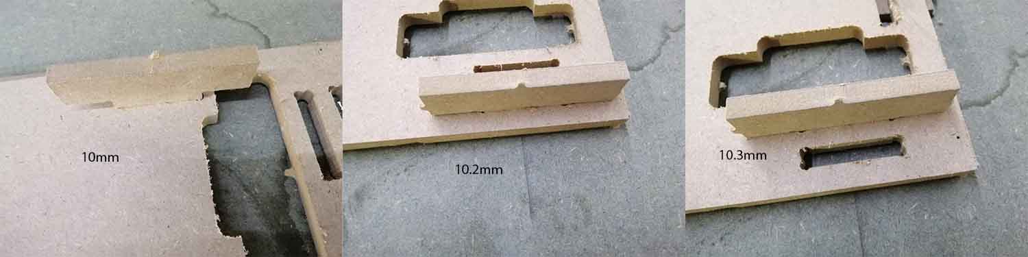
Measure the Kerf:
I made a design on artcam a piece with width of 50mm and length of 10mm same as the thickness of the board to be fitted into inside cut profile of also 50mm width and 10mm length, and other one of the same width and 10.2mm length.
Then added anther one with length of 10.3mm to make sure which one I preferer.
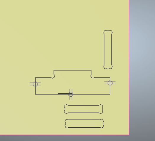
The thickness of the board was 10mm.
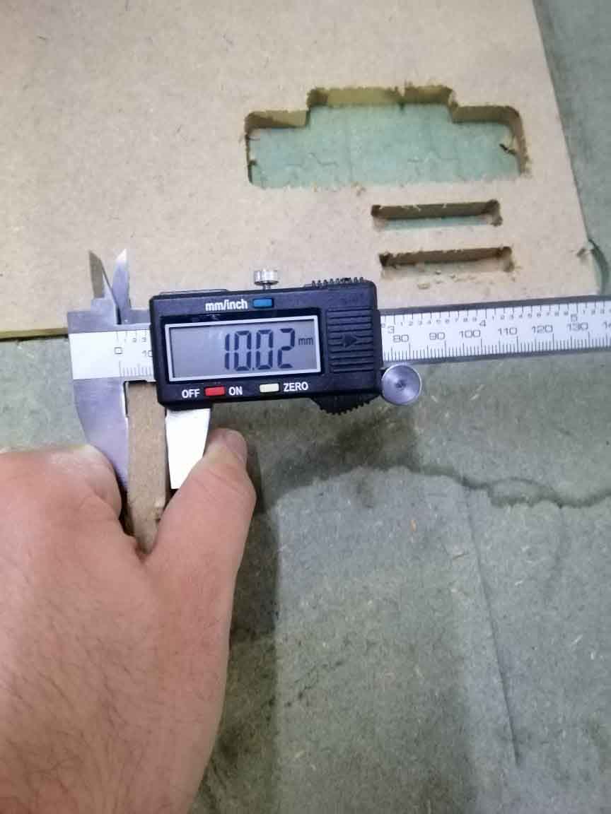
The best fit one was with the thickness of 10.2mm.
Design:
This one I have made it on my CNC machine in my workshop.
Design on Blender 2.79:
I have download image from dimensions.guide, and download the picture below:

And trace it on blender
The 3D file:
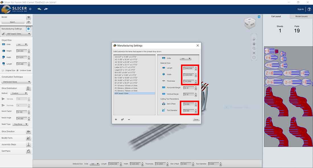
Put the model on Slicer:
Prepare the Manufacturing settings:
As you can see in the picture bellow, I have made new profile with the thickness of 10.2mm and offset zero, change the length and the width as same as the stander board, and put the tool diameter that I will work on 6mm endmill upcut.
And I scale it to be 60cm height, 71.6cm width, and 22.4cm length.
The I choose the interlocked slices, as you can see there was an error in the right side of the screen.
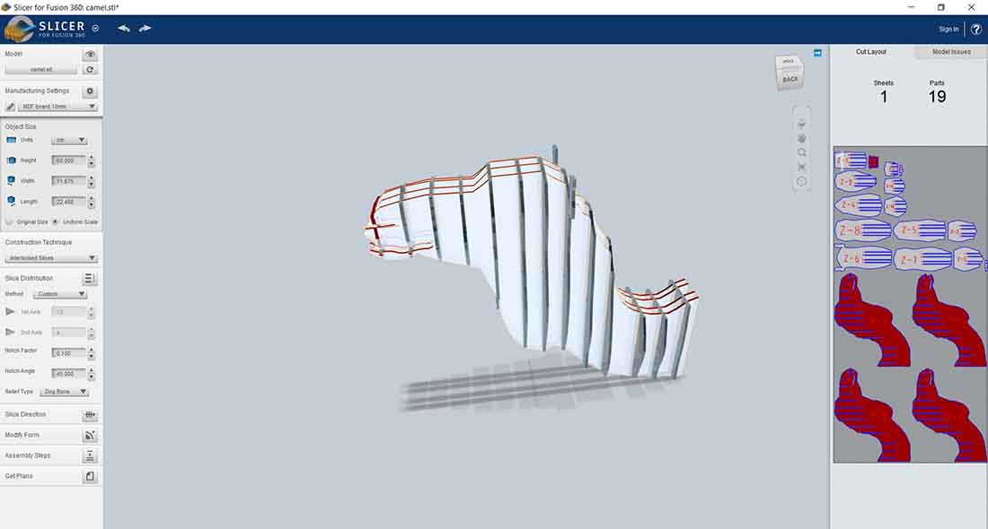
We can eliminate that problem by moving the part around the mouth area.
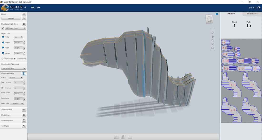
Or we can modify the small slices to no interlock with mouth and nose area, it can be modify on Blender or Artcam.
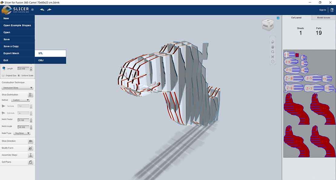
Also I want to add a pedestal, so I need to export the model as a STL file, and import it back to Blender.
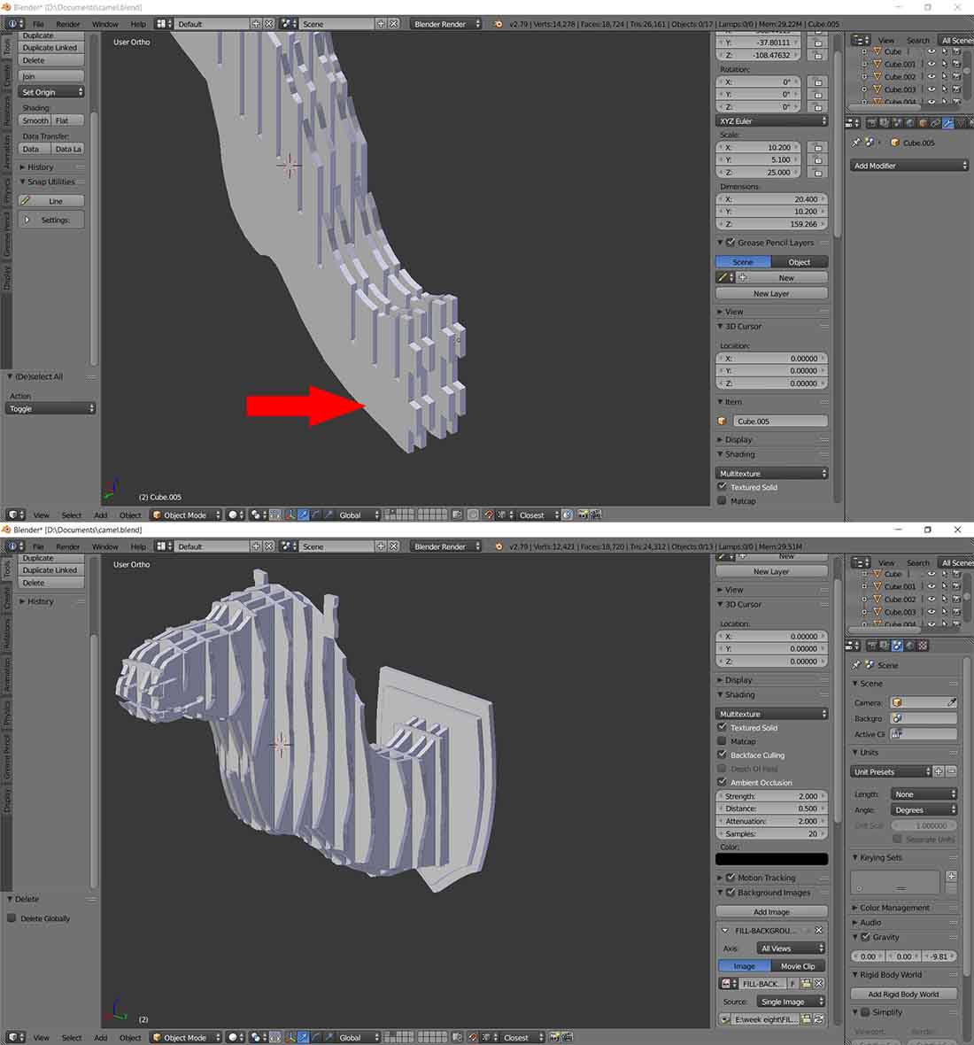
Back to Blender:
I have added to the Y-axis of the model a fittings to be mounted on the pedestal, while keeping in mind the kerf to the pedestal.
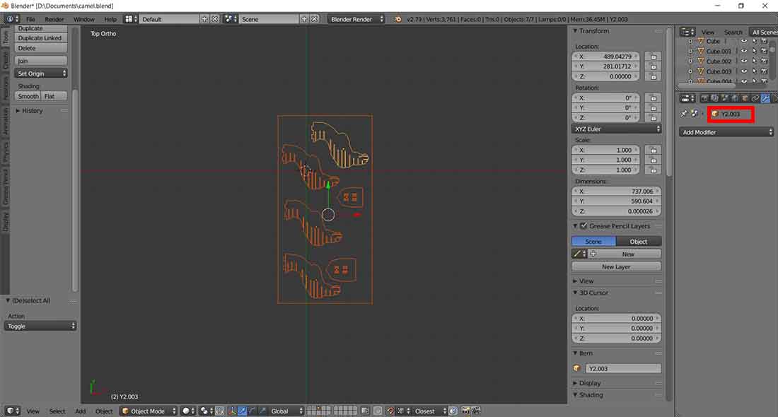
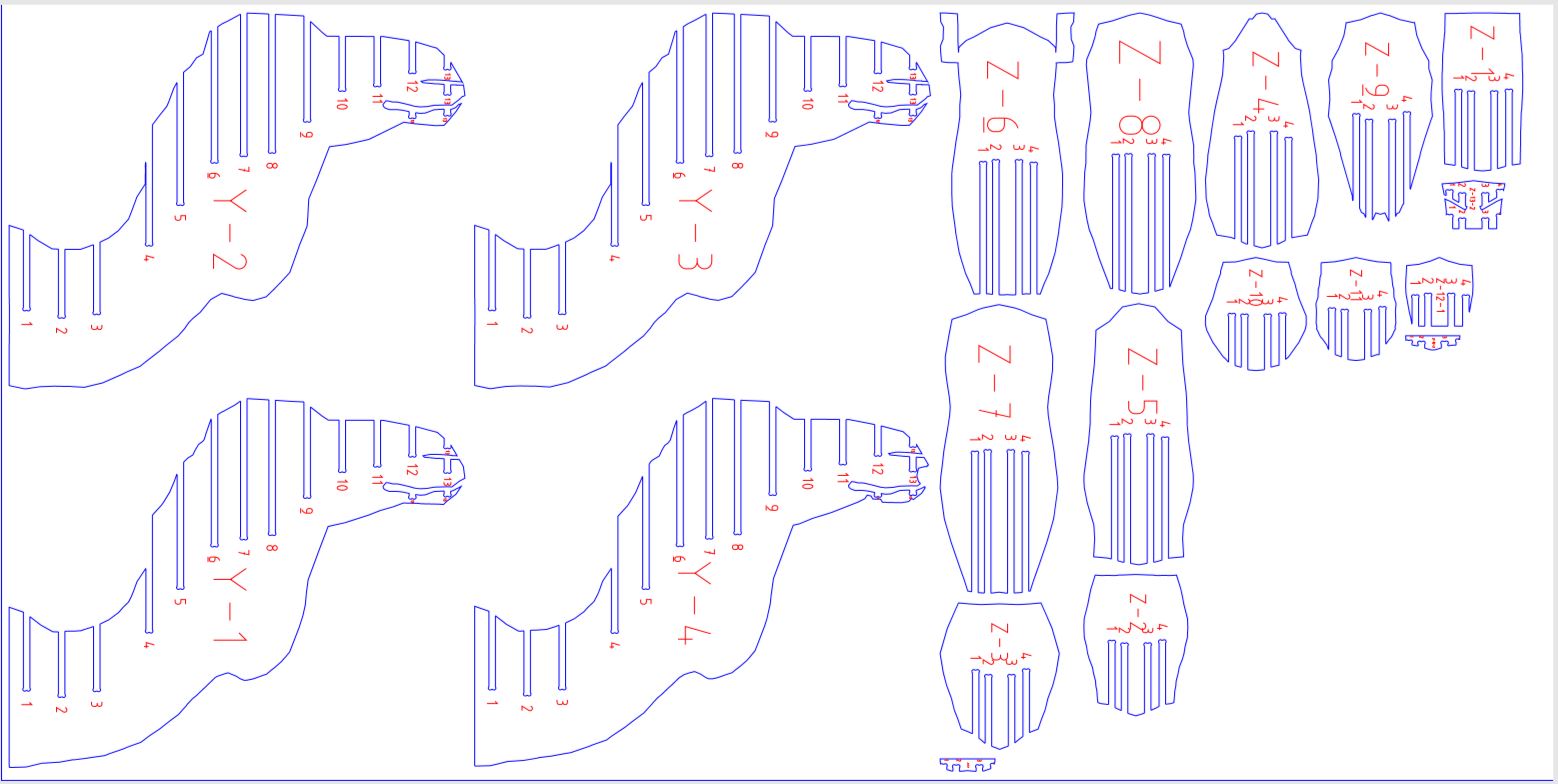
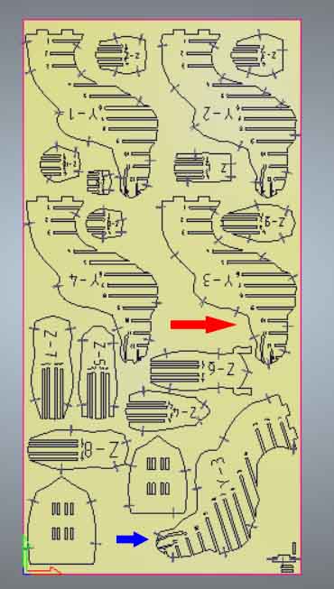
Then export the modified parts from blender to Artcam, as well as export the plans from Slicer.
As you can see below, in the red box I have named the parts like the naming in Slicer to make reference.
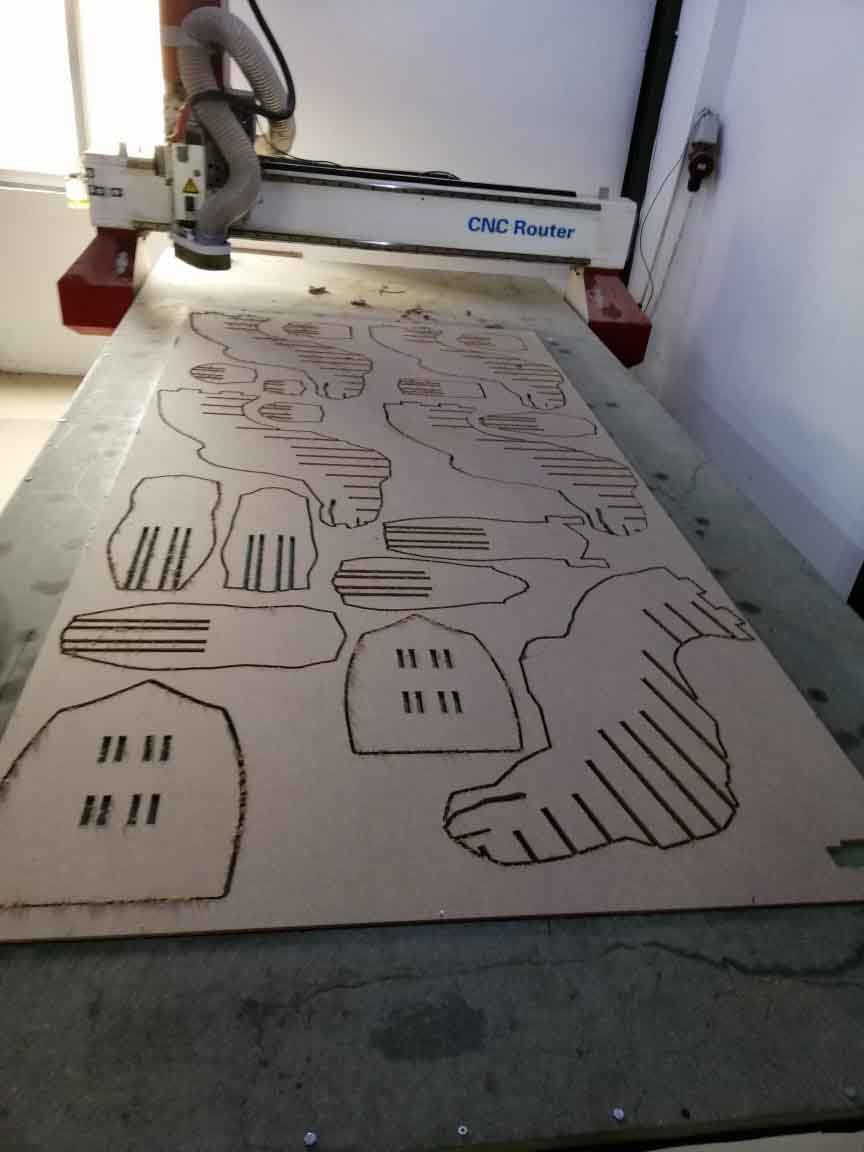
Artcam:
I imported the files into art cam and rearranged the vectors, and I made part of the board empty if there is any failure in cutting the parts.
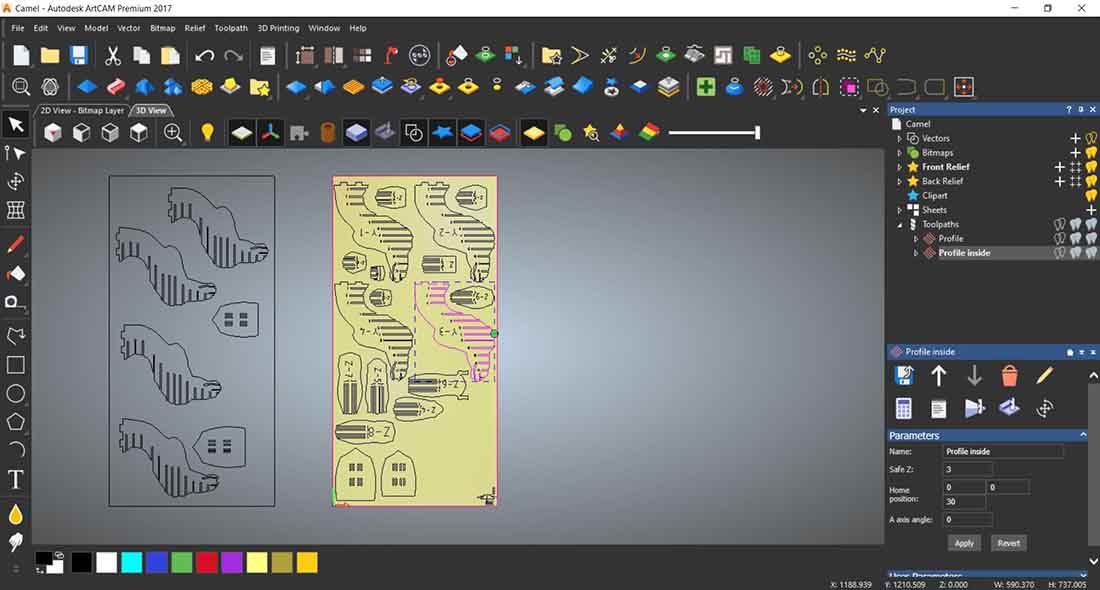
I choose a 6mm endmill with stepdown of 3mm, but the NCstudio will not take the Feed rate, Plunge rate and Spindle rate from Artcam, I must put the values manually.
The finish depth was more to cut the board properly.
And I added bridges/ taps to the vectors manually, and already
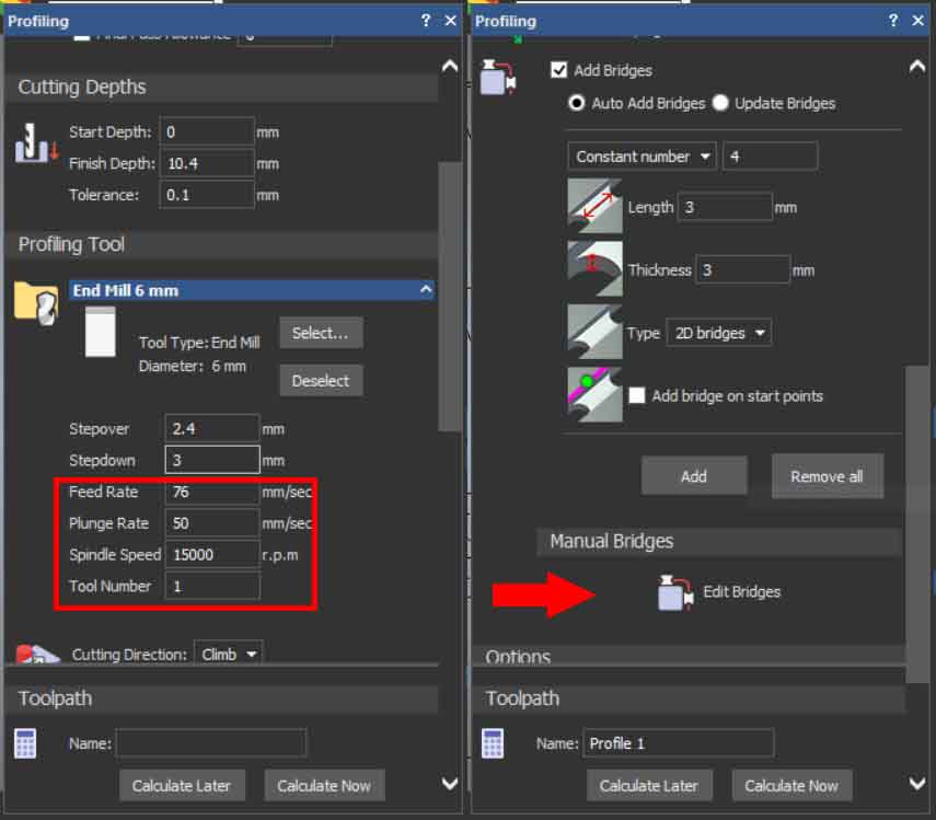
Then hit the Calculate Now to generate the toolpaths, then save it as a NC file which contain the Gcode.
NCstudio:
From the FSWizard Machinist Calculator, I put the values of my endmill bit as shown bellow.
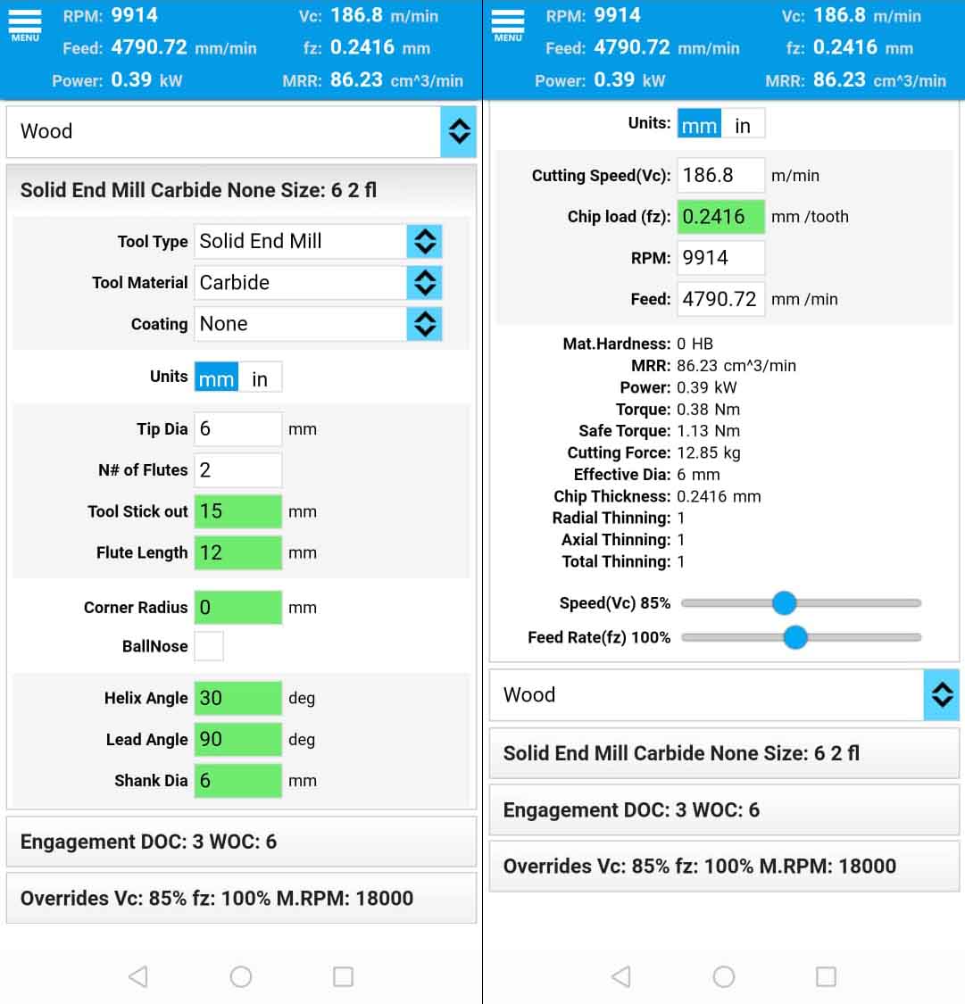
Then I put the values in NCstudio from the sliders shown in the picture bellow, zero out the Z axis on the surface then press start.
Cutting the parts:
But I made a mistake to not put more enough bridges/tabs around the nose/mouth area on one of the parts and had to cut it again.
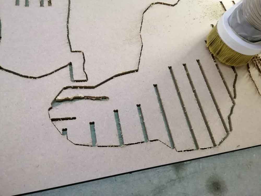
And I have to make one more from the space I had saved up for failures.
And the final result.
Assemble:
Using the rubber hammer, I assembled the parts
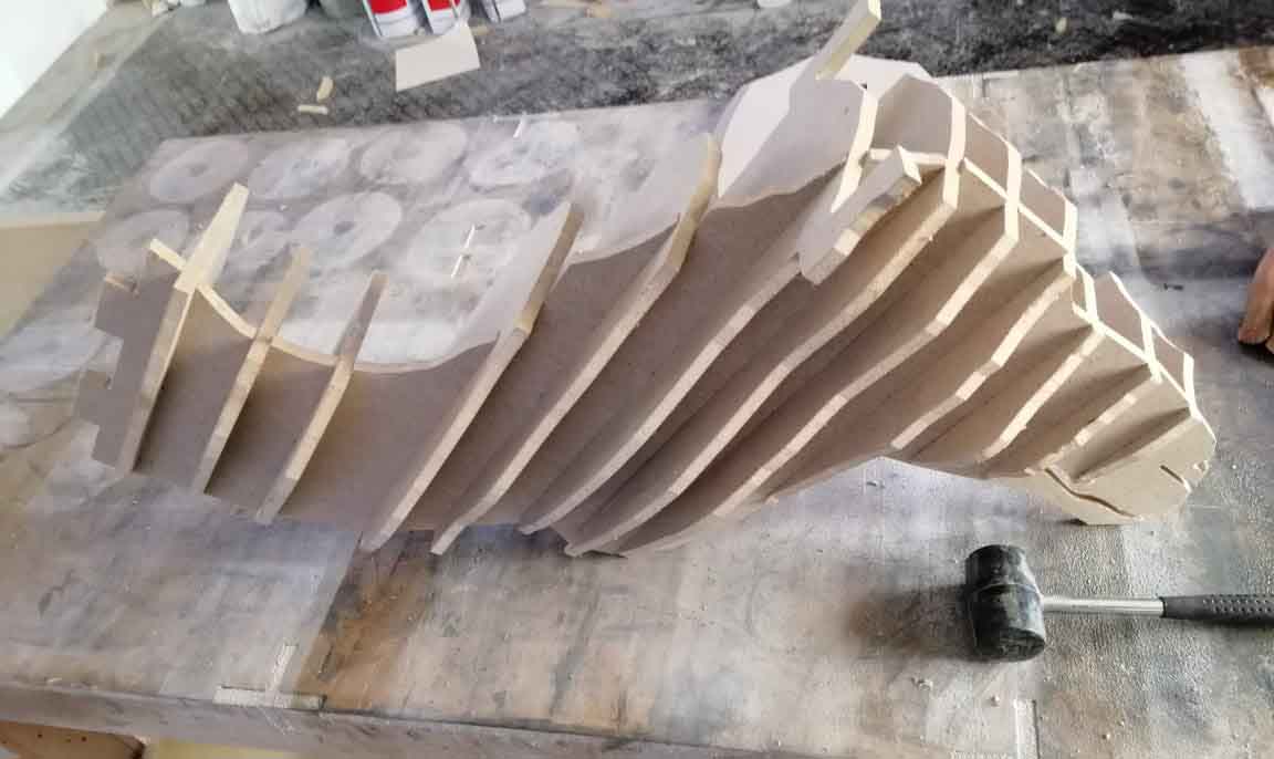
But I had some trouble assemble them, because I should have reduced the big parts from 4 to 3.
And redo the assembly by starting from the pedestal that I have made, it was a lot
easier.
Hero Shoots: