7. Electronics design
Download files:
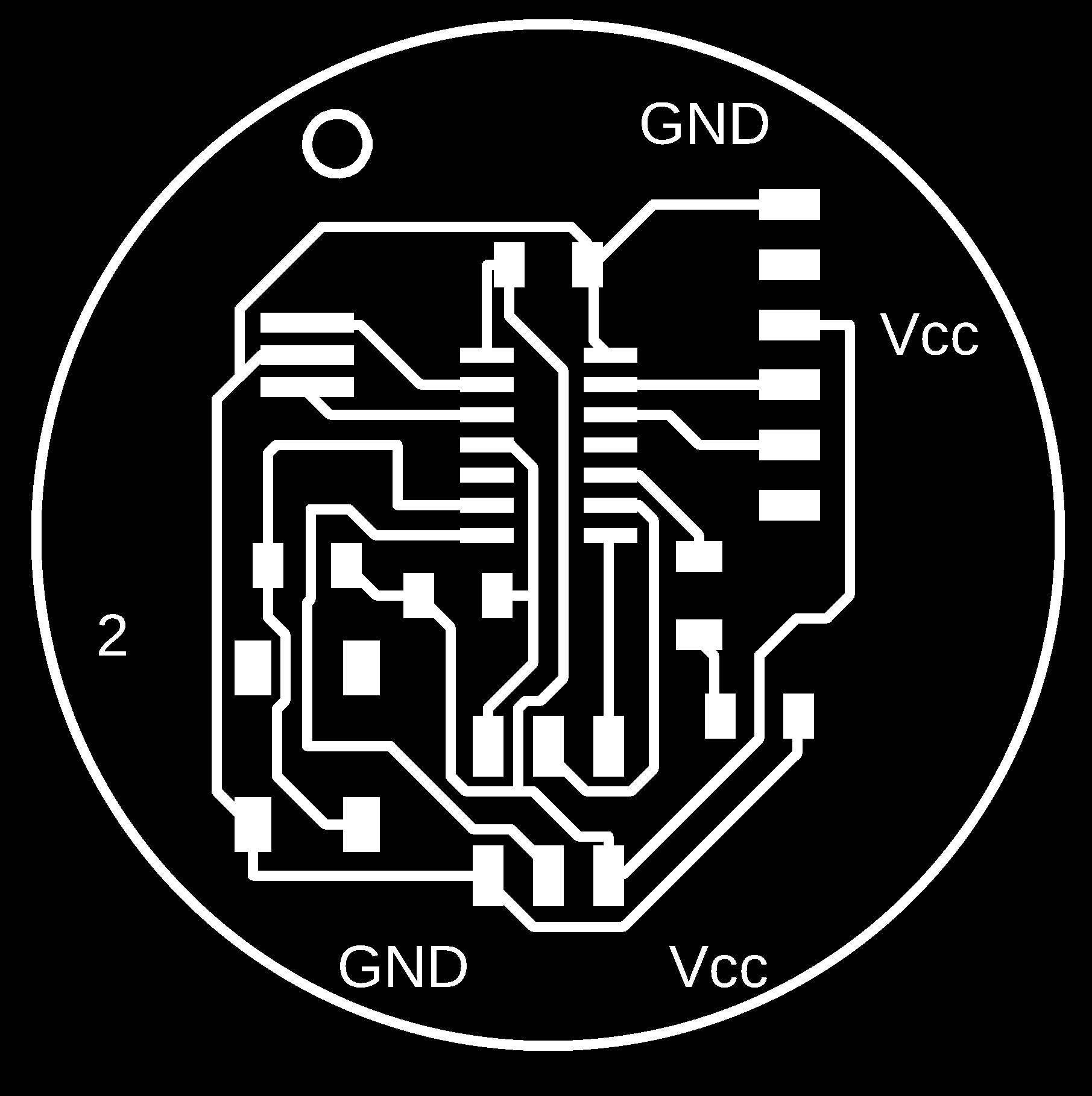
New board2 PNG
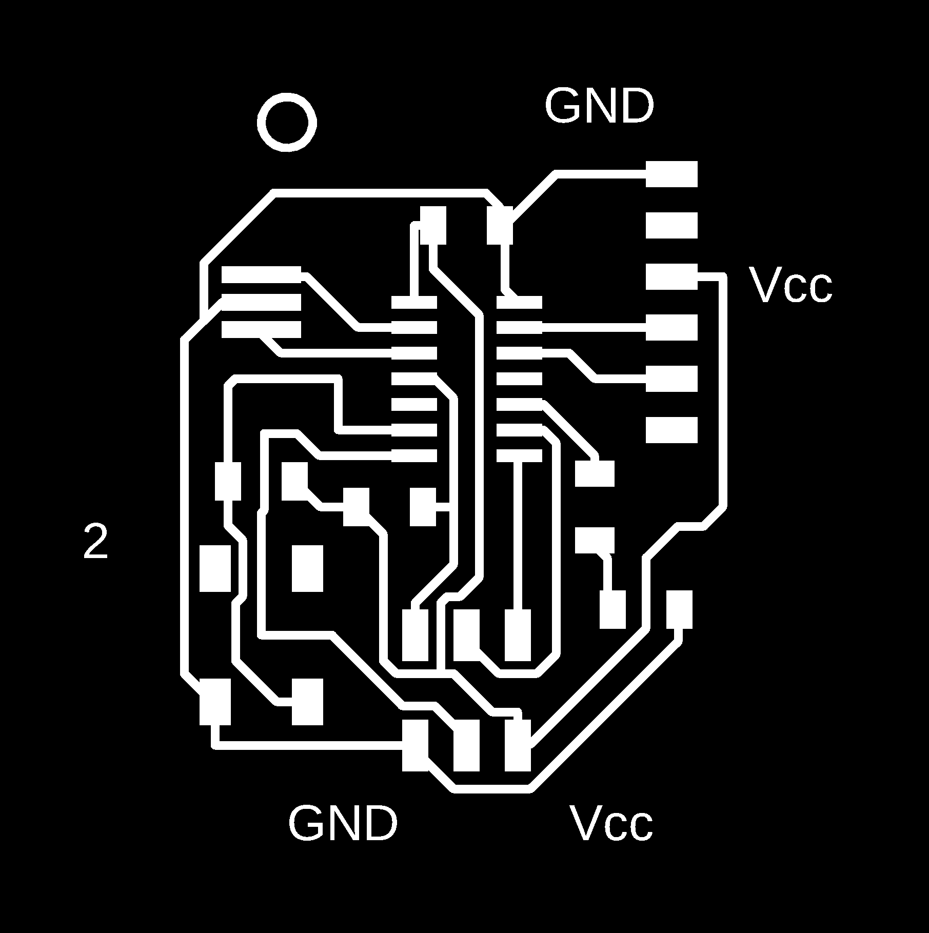
board_Interior_2 PNG
board_traces_2 PNG
board_Interior_2 RML
board_Interior_2 RML
Eagle files
Group Assignment
Objectives:
Test a microcontroller circuit board by using equipment in your lab.
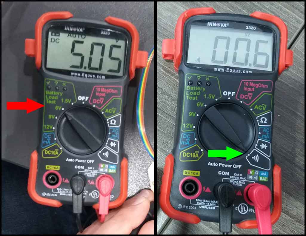
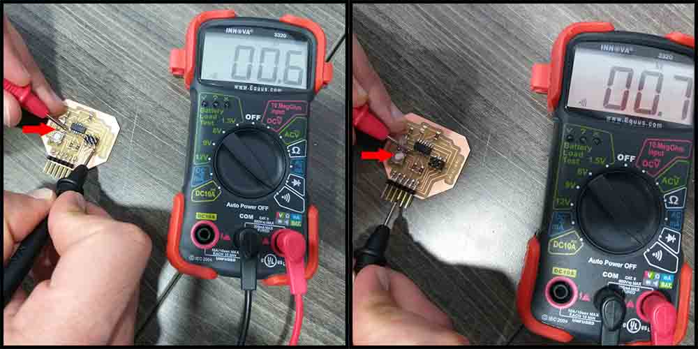
In group assignment we used the digital multimeter to check the continuity between ground pins and Vcc pins. Also, we measured the VCC to GND voltage, which should be 5V.
GND (Ground) Continuity
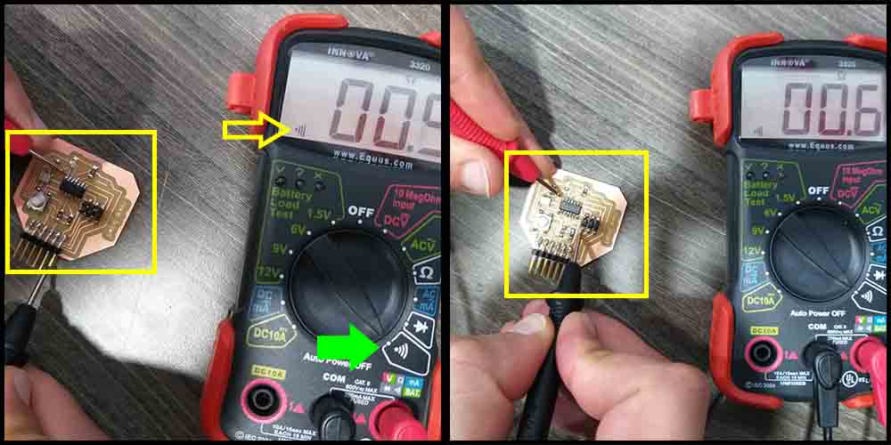
We measured the continuity between the GND pins of the ATtiny44, SPI header and FTDI header. The digital multimeter should beep and read around 0 Ohm. This means all the three pins are connected.
VCC (5V) Continuity
We measured the continuity between the VCC pins of the ATtiny44, SPI header and FTDI header. The digital multimeter should beep and read around 0 Ohm. This means all the three pins are connected.
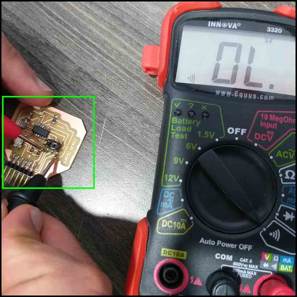
VCC-GND Continuity
We measured the continuity between the VCC pin and GND pin. The digital multimeter should not beep and read OL (Overload). This means there is no connection (short circuit) between the VCC and GND.
VCC to GND Voltage
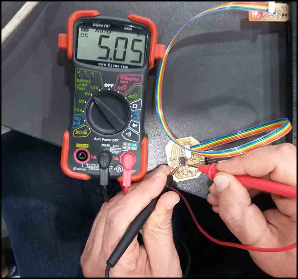
We connected the board to the FabTiny programmer and then to USB. We measured the voltage between the Vcc pin and GND pin. The digital multimeter read 5V, which is the value of USB port voltage or the Vcc.
individual Assignment:
Objectives:
Redraw an echo hello-world board, add (at least) a button and LED (with current-limiting resistor) check the design rules, make it, and test it.
Then copy the Eagle’s library in the C:\Users\(your user'sname)\Documents\EAGLE\libraries, then open new Eagle Schematic file.
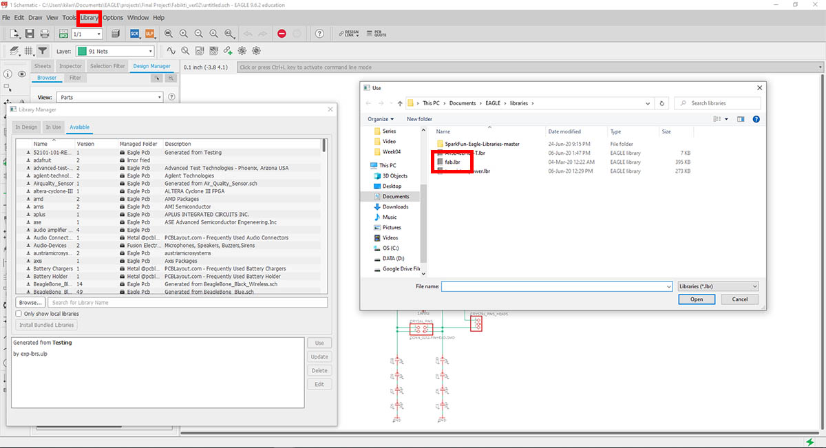
From
Library ---> Library Manager
Go to the Available tab, then click on Browse, then choose the fab.lbr file.
If it not the In design tab, go back to Available tab and search for fab, then click on use to activate it.
Install electronics library for eagle:
From the FabAcademy site under the electronics design week, we click on Libraries
Read, read, and read:
Following the instructions on the Fabacademy tutorials page, we can do the following:
- Read the Schematic Symbols.
- Download and Install the component Libraries.
- Use Eagle basics; Schematic and Board Layout.
- Naming the wires to auto connect in Schematic.
- Design rules check.
- Export PNG.
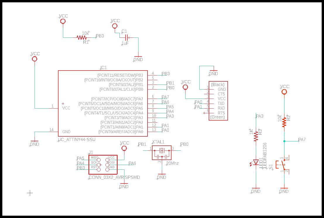
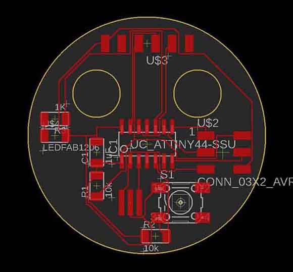
Eagle Schematic:
I have done multiple schematics until I have got it right, as well as changing the wires to have a better connections between the electronic components.
Also I made the mistake that I was loading the wrong Design rules check, the eagle default, not fab DRC.
Table of Parts:
| Part Name | Footprint name | Number |
|---|---|---|
| 03x02 Connecter AVRISP | 2X03SMD | 1 |
| 06_FTDI-SMD-HEADER | 1X06SMD | 1 |
| LED (Blue) | LED1206FAB | 1 |
| Resistor 10K Ohm | R1206FAB | 2 |
| Resistor 1K Ohm | R1206FAB | 1 |
| SWITCH_TACTILE_6MM | 6MM_SWITCH | 1 |
| ATTINY44 | SOIC14 | 1 |
| XTAL_RESONATOR | EFOBM | 1 |
| CAP_UNPOLARIZED | C1206FAB | 1 |
Failed connection:
-
I made a wrong connections, I noticed them when I have done a double check on them using my notes.
-
Also changed the pins that were connected to the push button and the LED with its resistor.
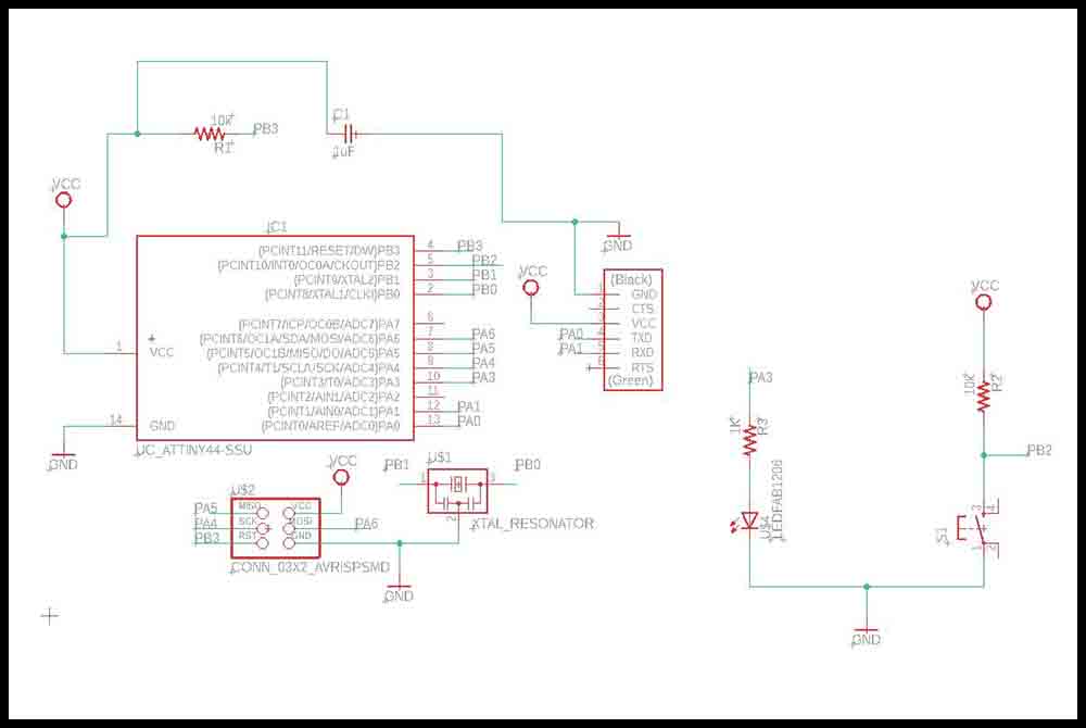
Right connection:
I have separated the Vcc and GND for each component, and picked better pins for the push button and the LED with its resistor.
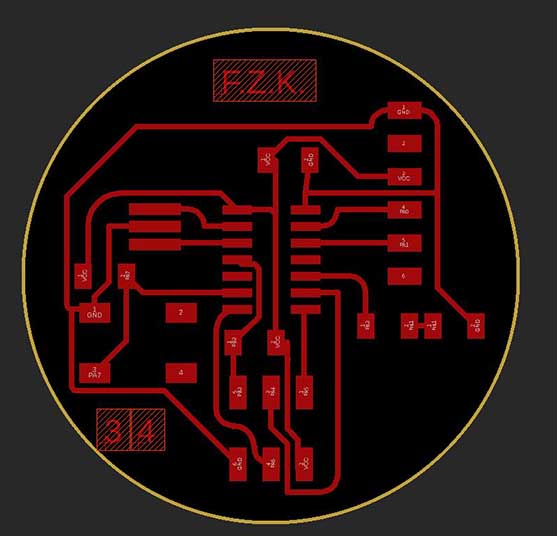
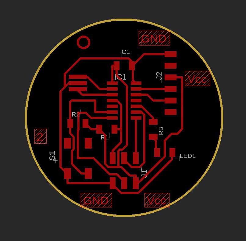
Board Layout:
The First Board layout was wrong because I selected the wrong DRC file; the default from Eagle, the line width was small, and the connections were connected wrong.
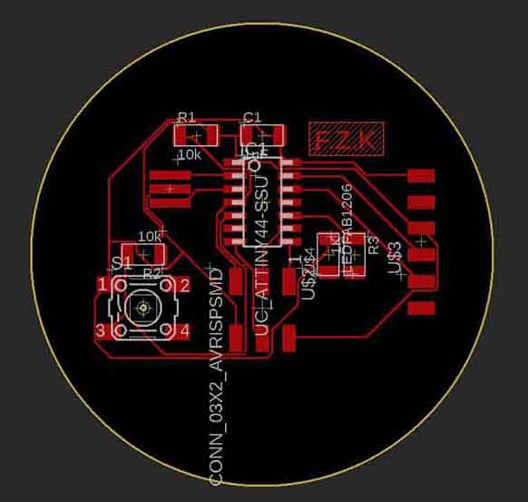
The second try I just fixed the connections, but still the I loaded the wrong DRC file.
The third try, I have loaded the right DRC file, and after multiple positioning of the electronic components; more than five or six tries, I have got it right using auto routing.
Also I have renamed the components symbols
From random name ----> LED
FTDI             ----> J2
Header 3x2       ----> J1
The resonator    ----> XTAL1
Push button      ----> S1
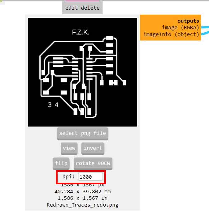
The fourth try, I added pin numbers for the Push button to know the orientation placement of the button marking 3 and 4, but however in mods I had the problem that traces path tool did not remove some parts as it should.
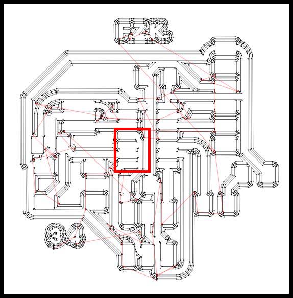
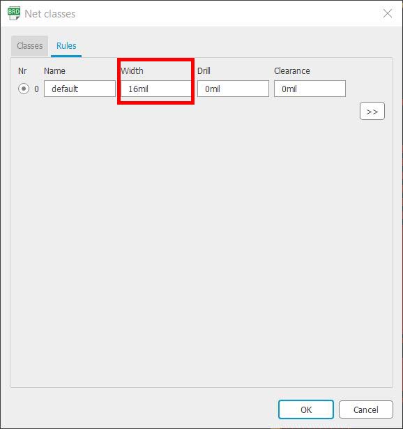
So I have googled the issue and I have found out I can put the line width beforehand, from Net classes under the Rules tab and change the width into 16mil.
I redo the board design, put the right DRC and Net classes to the correct values, and put more ground indications, pins indications for the button, and small circle for the ATtiny 44.
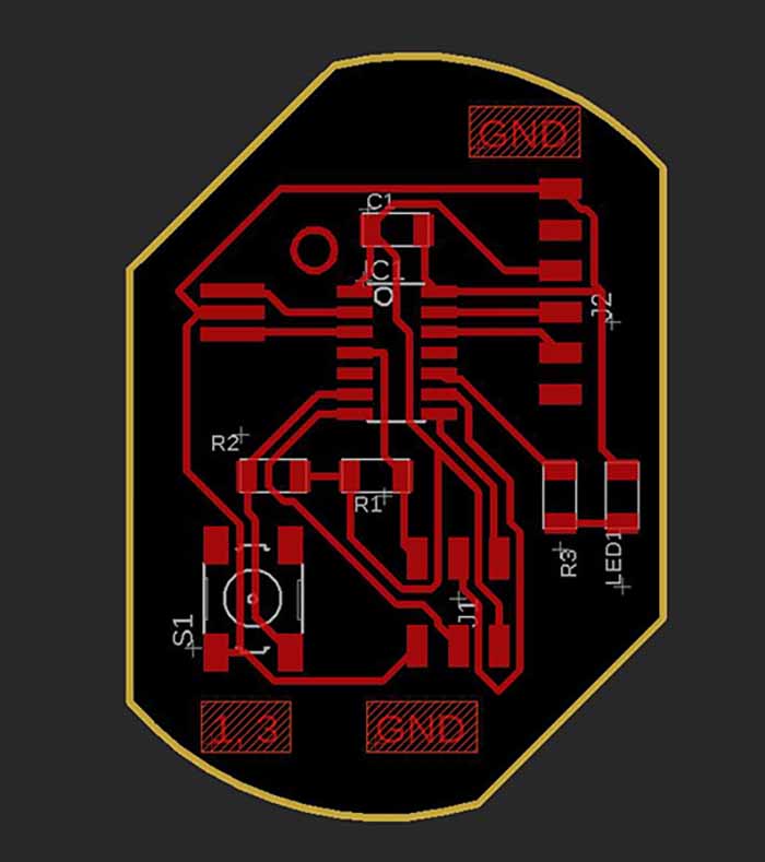
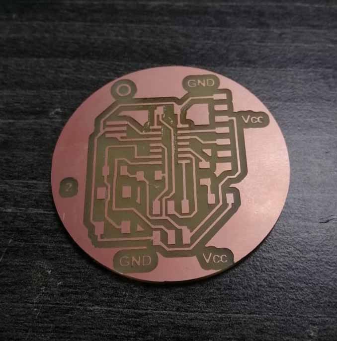
But when I mill it was short circuit, I have mill it with a worn down milling bit, with the default settings of the bits in mods.
The last one, added Vcc indications on the board, and moved the components further from each other.
Preparing and milling the PCB:
Mods settings:
- Change origin:
    From      To
X   10        0
Y   10        0
Z   10        0
- Mill traces settings:
Default settings but the last mill I have changed the fill from 4 to 5.
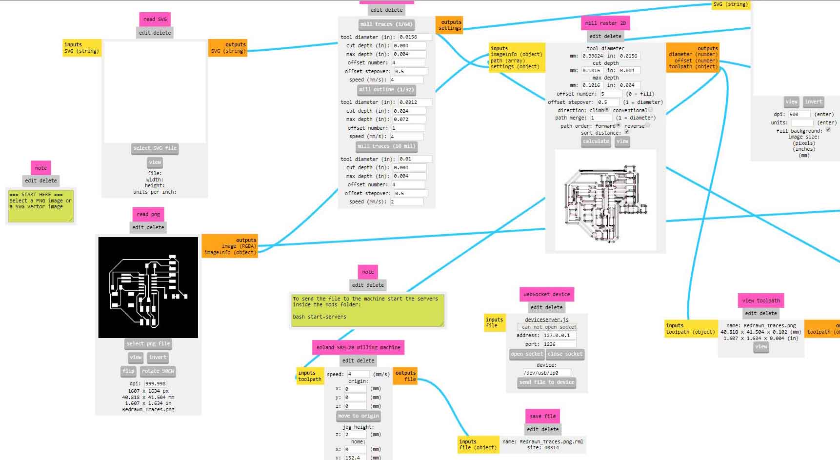
- Mill interior settings:
Default settings, did not change.
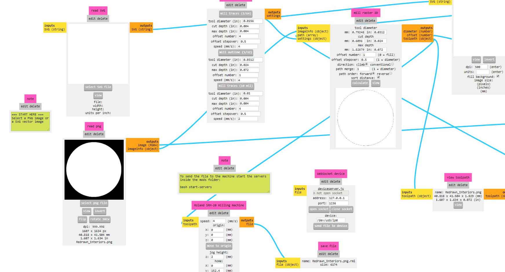
- DPI settings:
Make sure that it is matching to the ones exported from Eagle.
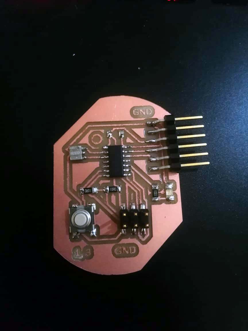
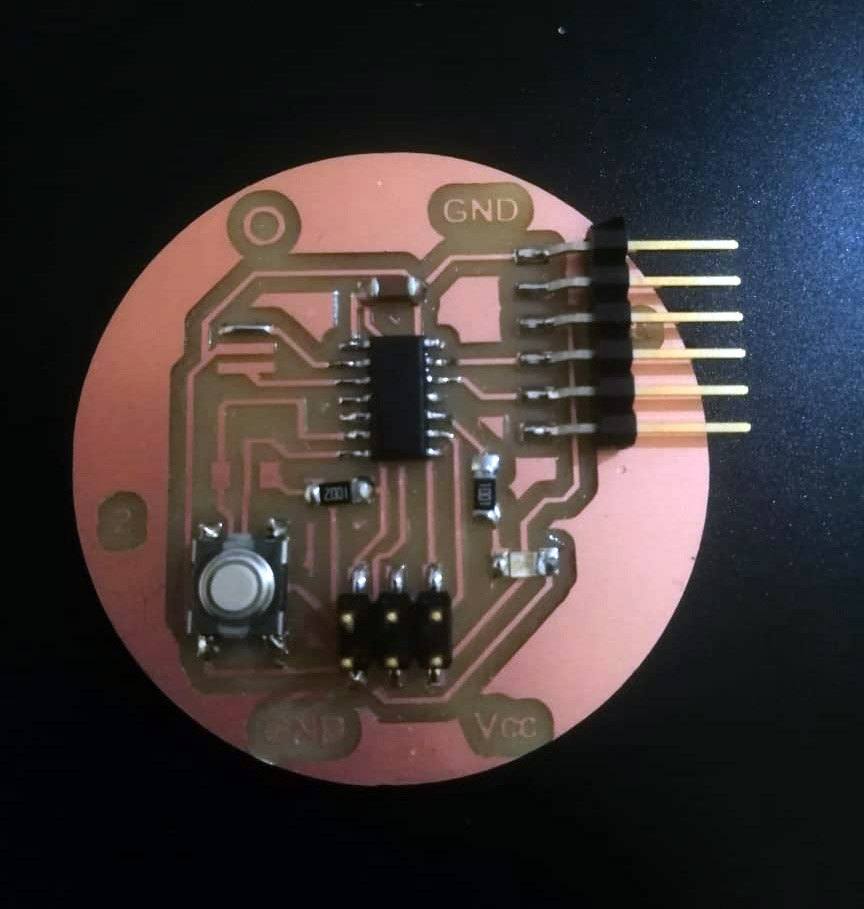
Soldering the components on the PCB:
Sadly this one did not work properly as mentioned before.
Also I have failed in the order of soldering the electronic components, which is:
- The microcontroller first.
- Then the other small components.
- Lost the jumpers.
The last one that I have milled, with fill 5.
Problem with the circuit:
As there was issue with the boards, after upload the program the first time, there was an issue that the ATtiny44 will not be programmed again.
-
Checked the circuit with the multimeter for continuity of all copper wires, and if there was a short circuit.
-
Maybe there was a problem with the XTAL_RESONATOR that we had with wrong values.
-
The heat gun in the lab is broken, and we will get another one next week, we could not check any further problems.
So as I have been instructed that I should not add the resonator to the circuit until we figure out the problem.
But after that, we figure out that I have make the mistake with the resonator soldering.
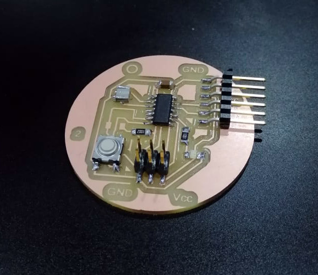
Hero Shoot:
Files:
All final files are put in the link below.
Test the circuit:
It is not hello world program, but is blinking LED on OFF for a span of 5 seconds, without the resonator, at the internal 8 MHz.