1. Principles and practices
Assignment two:
Describe your final project.
Auto level detector for large CNC
Note: Work in progress.
 +
+ ---->
----> ---->
---->
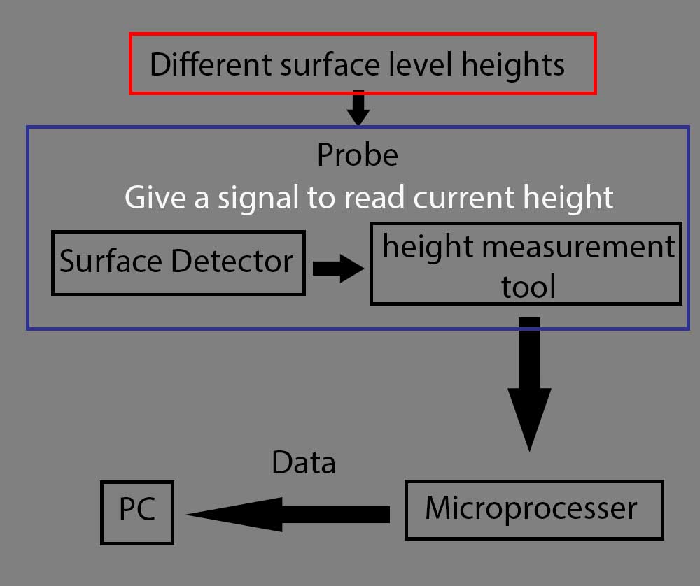
I want to make a probe that is separated from the machine Electronics, and it can automatically measure on a large CNC machine different surface/ level points across standard wooden sheet which is 2440 height and 1220 width, and send the acquired data to a PC to compensate the difference between the surface levels and g-code.
Where a simple CNC Touch Plate can not do the job if we have multiple uneven surface points, and we have to do compensate the difference manually to a program can generate g-codes.
And the another problem is that the software that comes with the CNC machine usually do not have automatic compensation and it is closed software which can not be modified.
Inspiration
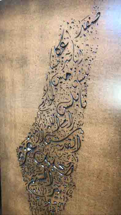
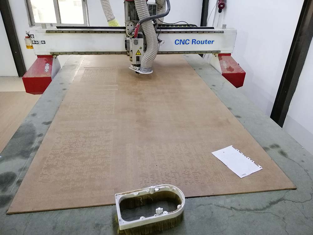
While working over a year on craving and make sings and Arabic calligraphy on wooden sheets with CNC machines, I notice that even after resurface the spoilboard the surface is uneven, or on other words the Z height is not consistent.
The causes of this problem that wood will wrap due to humidity, temperature and bad storage facilities, and sometime it is hard to detect the surface in the naked eye, and margin of error is ±0.1mm too much is sometimes it too much and will take effect the on the worked piece if there were high details on them, especially the work of the operation take a long time.
Example: you can see the small change on the level surface/ height, and compare it to how it should be.
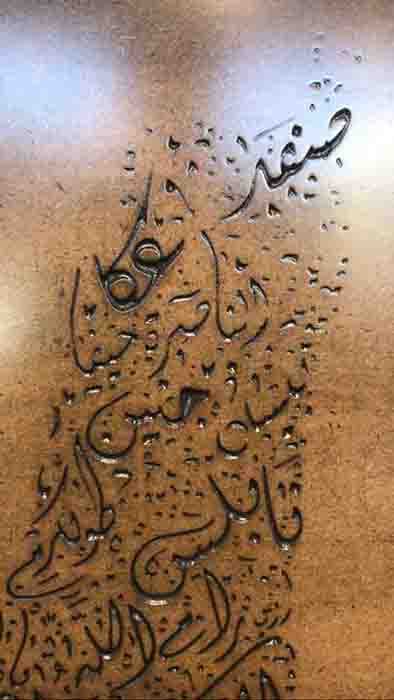
And this is how it should be:

Research
Showcase: It is a universal problem
Here someone asking about uneven surfaces
Hello,
I’ve been doing v-cutting on surfaces to make nice lettering and stuff.
With v-cutters I noticed that the z-height is very critical.
I sometimes machine a new face onto the material first to guarantee it’s level.
I even find that difficult sometimes, I wonder if the piece moves or something.
Any thoughts on this
Anybody noticed when using v-cutters things are so Z-tricky?
Hi all,
I know the proper way to handle this is to fix the table, but for now, does mach3 offer any kind of uneven table compensation? For example, I have one corner that is about 1/32 of an inch off. When I V-Carve down to that corner the change in my carving changes dramatically, that the width of my path is exactly off by twice the Z error. (Assuming 90* bit)
Any way I can tell my software “that corner is high/low?”
Inconsistent Z Axis Cut Depths on a CNC Router:
From the original questioner:
I normally use a spoilboard - sheet of MDF which I then machine about 1.5 mm off the top to supposedly get a completely level surface. Then I place the material to be engraved on the top and still get an engraved depth which differs at different parts of the table. I even tried routering out three 25mm wide sections right down the length of the spoilboard (on the left side, middle, and right side of the table) and then with the same tool engraving three separate 3mm wide sections down the same routered areas and still I get a differing engraved depth.
Similar option but in smaller range, or not automatic:
But the problem is the program can not work on all CNC machines.
2- Auto Leveling your CNC Bed manually.
He worked on an open source small CNC machine, and there is no hassle to take the surface level semi-manually unlike the large one.
And also he disconnected limit switch of the Z-axis to do this procedure.
Sketch
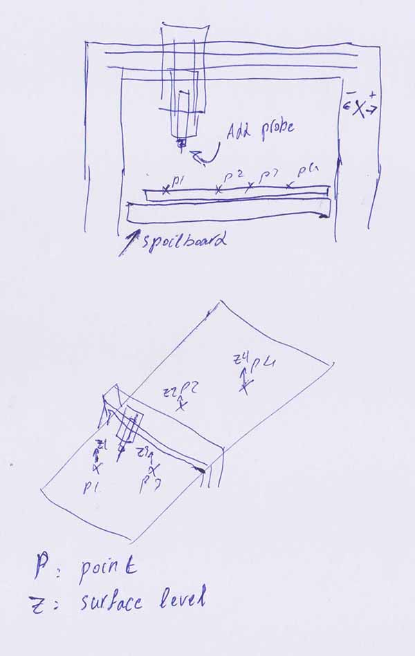
Shows the points on a stander sheet and distance between them are large.
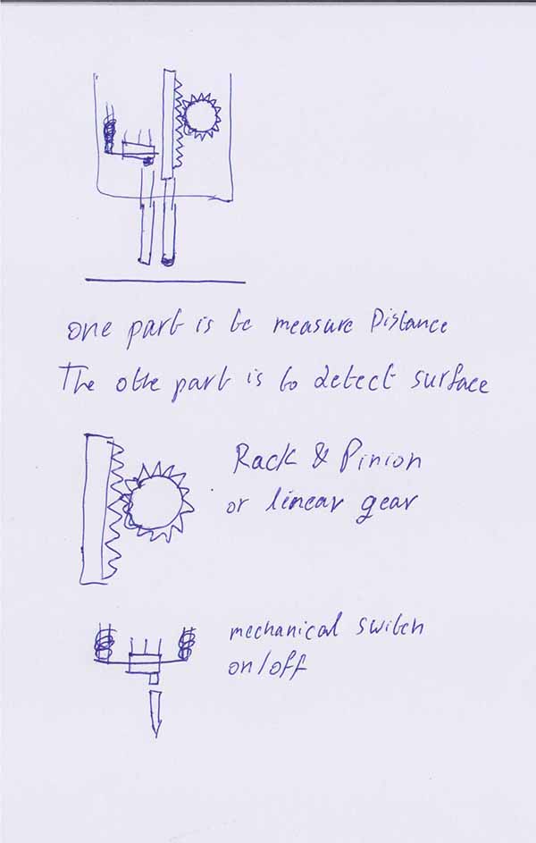
My first draft is to make it by using linear gear and mechanical on-off switch, where one detect the surface and the other is to read the difference with in small range.
Machines:
1- 3d printer.
2- Laser machine.
3- PCB machine.
Materials:
1- PLA plastic.
2- Springs.
3- Wood for electric enclosure.
Electronics:
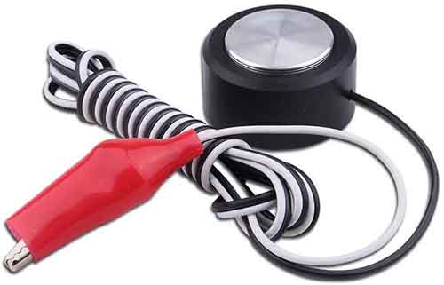
1- Rotary encoder: to read the measurement from linear gear.
2- On/Off Switch: to detect the surface.
3- Arduino: to collect the data.
4- Bluetooth, or USB hub: for communications.