10. Input devices
This week we did not have access the lab, so I will update it later when it is done.
Download files:
EML files:
Main board Traces
Main board Outline
Input board Traces
Input board Outline
PNG files:
Main board Traces
Main board Outline
Input board Traces
Input board Outline
Eagle Files:
Click to download
Codes:
Assignment Objectives:
Individual assignment:
Measure something: add a sensor to a microcontroller board that you have designed and read it.
Group assignment:(Will be done later)
Probe an input device’s analog levels and digital signals.
Group assignment:
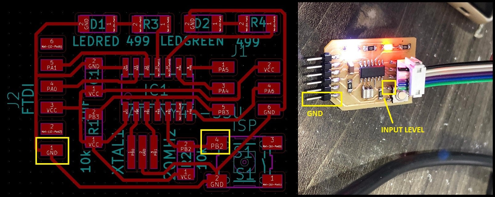
For the group assignment this week we have to probe an input device’s analog levels and digital signals and to do that we have measured the level of a push button that my colleague Aziz have done in its two states, normal and pressed.
- The push button (normally open) is connected to
Vccthrough 10kOhm resistor, so in its normal state the level will be5V(digitally high). When pressed the level will be0V(digitally low).
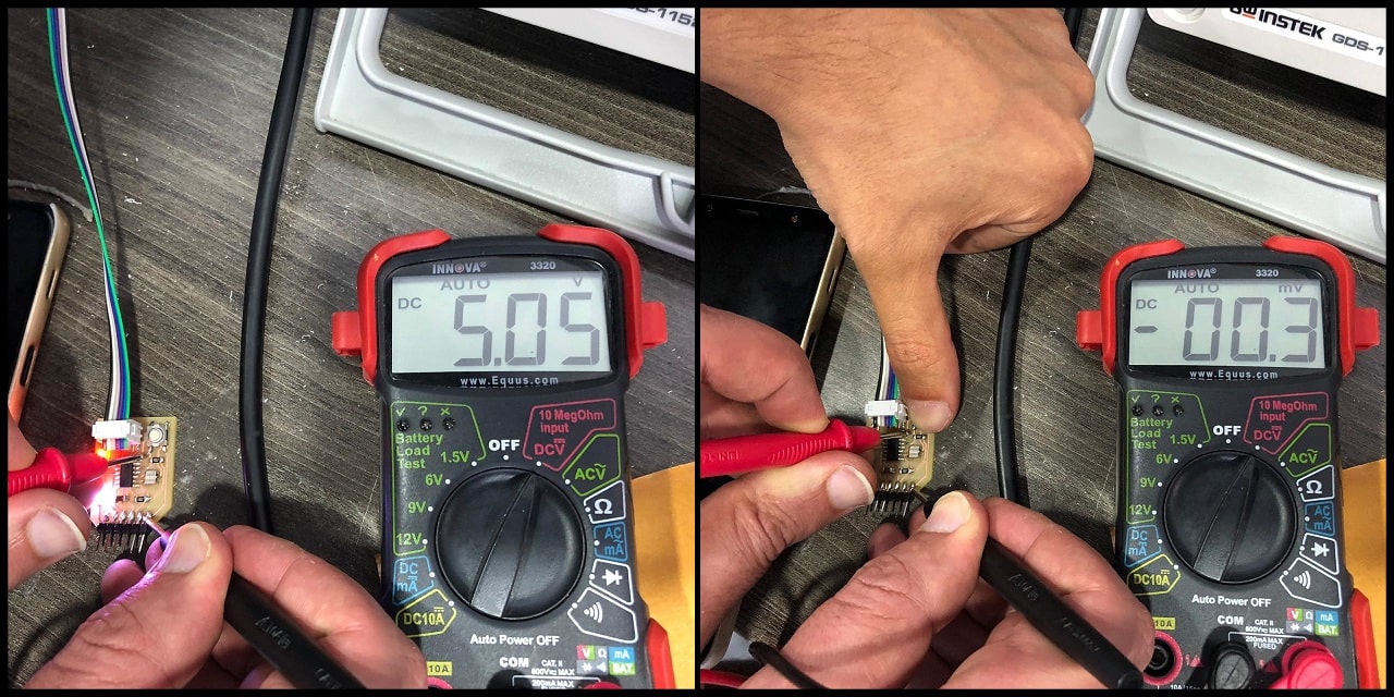
- Using the digital multimeter, in the normal state the measured value is
5.05 V(digitally1or high), and when pressed, the measured value is-0.3 mV(digitally0or low).
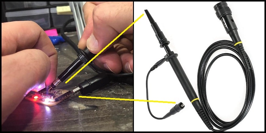
- We used oscilloscope to measure the same input signal. To connect the oscilloscope probe, connect the spring loaded end (hock or clamp) to GND and the pin head to test point, which is the push button signal.
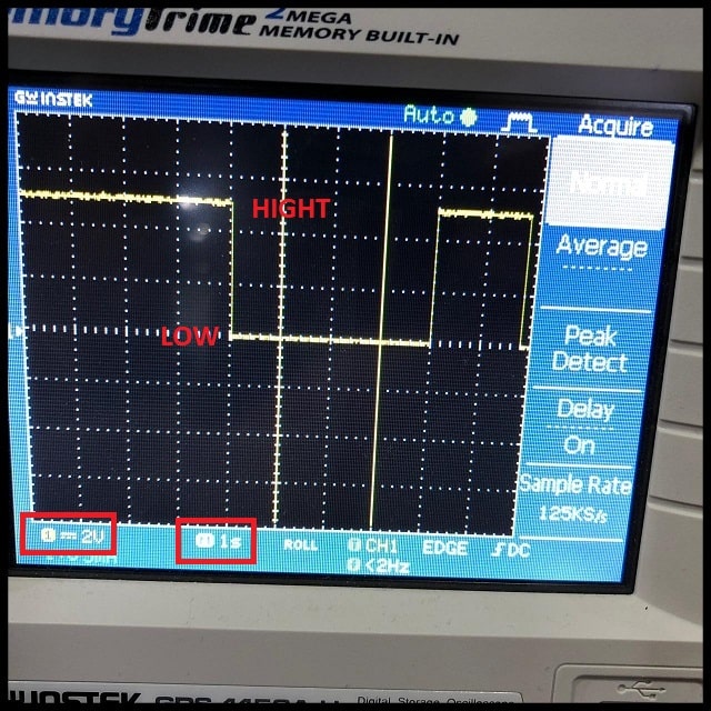
- Note that voltage scale is
2V/division and time scale is1s/division. In the normal state, the signal height is2.5vertical divisions, which equals to5V(2.5divisions x2V/division). When the button is pressed, the level drop to fit over the zero line. The button had been pressed for4seconds (4 horizontal divisions x1s/division).
Individual assignment:
Redesign the board:
The main idea is to make a main board (Hello World board) to be multi purpose; to be used in this week (Input week) and the output week.
Why redo the board from week07?
Because I want to free Pin03 to because it has a 8-bit bi-directional I/O port, unlike the PinB2 it has a 4-bit bi-directional I/O port.
Old board pin layout:

As you can see we have two free pins (green pins); one is 4-bit and the other is 8-bit.
PA7 is connected to a push button and PA3 to a LED.
Red pins cannot be changed; connected to voltage source, ground, resonator, and ISP pins.
PA0 and PA1 can is used for FTDI ports, but also it can be used for I/O when the serial communication is not used.
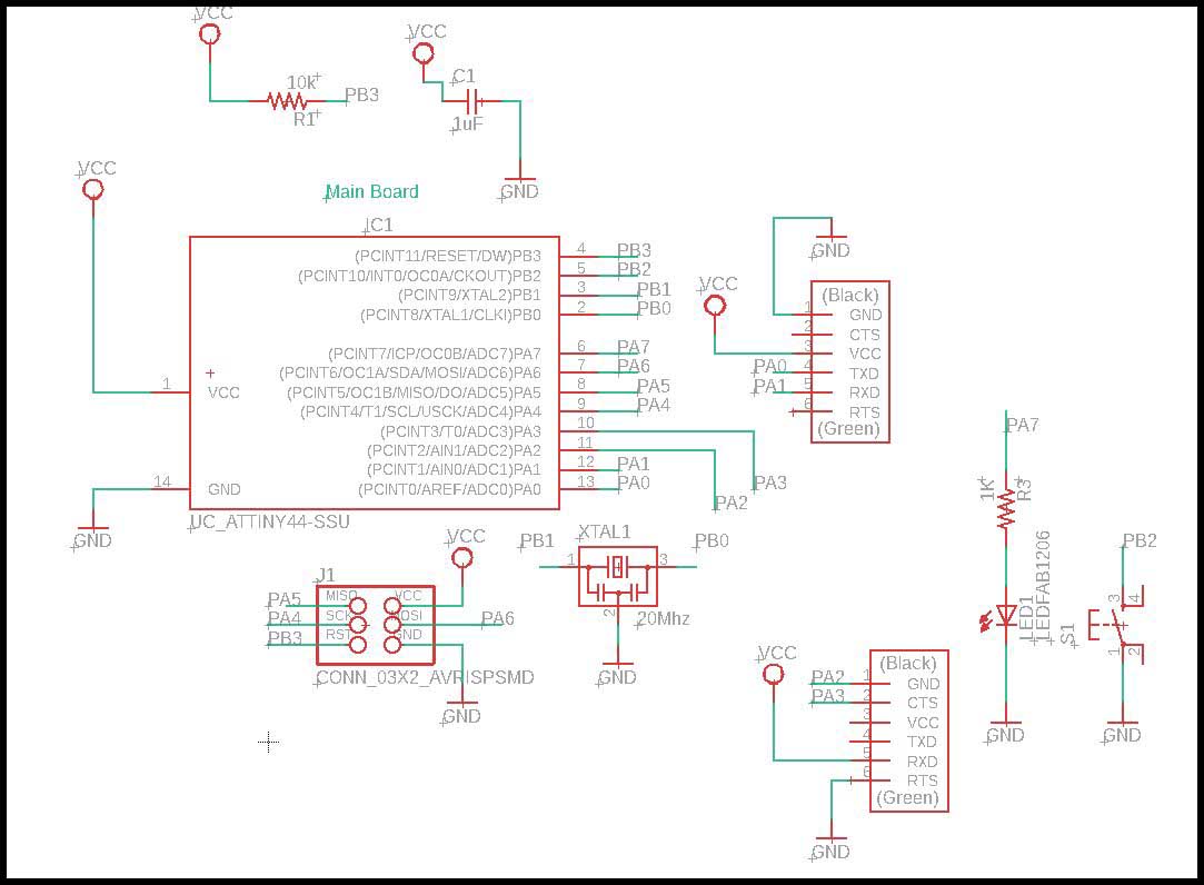
New board pin layout:
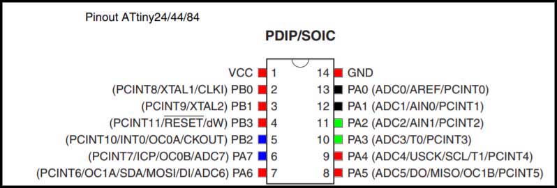
As you can see we have two free 8-bit pins (green pins).
PA7 is connected to a LED and PB2 to a push button.
Red pins cannot be changed; connected to voltage source, ground, resonator, and ISP pins.
PA0 and PA1 can is used for FTDI ports, but also it can be used for I/O when the serial communication is not used.
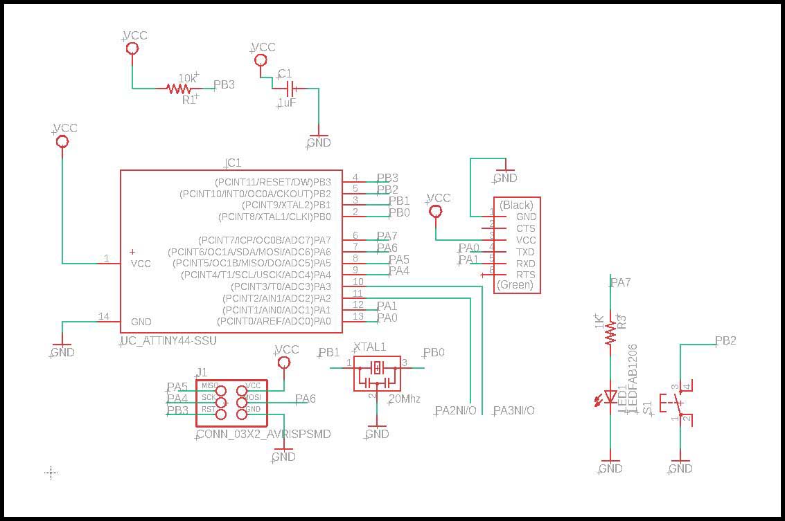
Change the Eagle file from week07:
The main Idea is to have at least two 8-bit pins free to use, and you could see from the New board pin layout we have PA2 and PA3.
PA7 is connected to a LED and PB2 to a push button; because it will give either HIGH or LOW signals, and maybe in the future I can use them for other purposes.
Also removed the pull up resistor, because the microcontroller has internal pull up resistor.
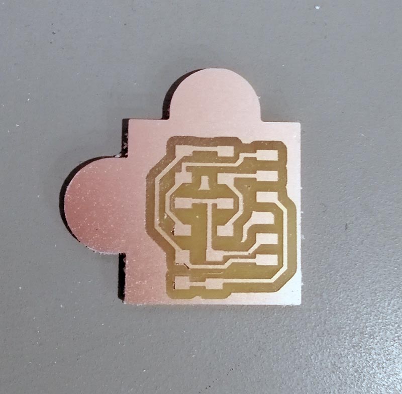
As you can see from the picture below, next to the blue arrow the traces have no pads, but I can add them using photoshop.
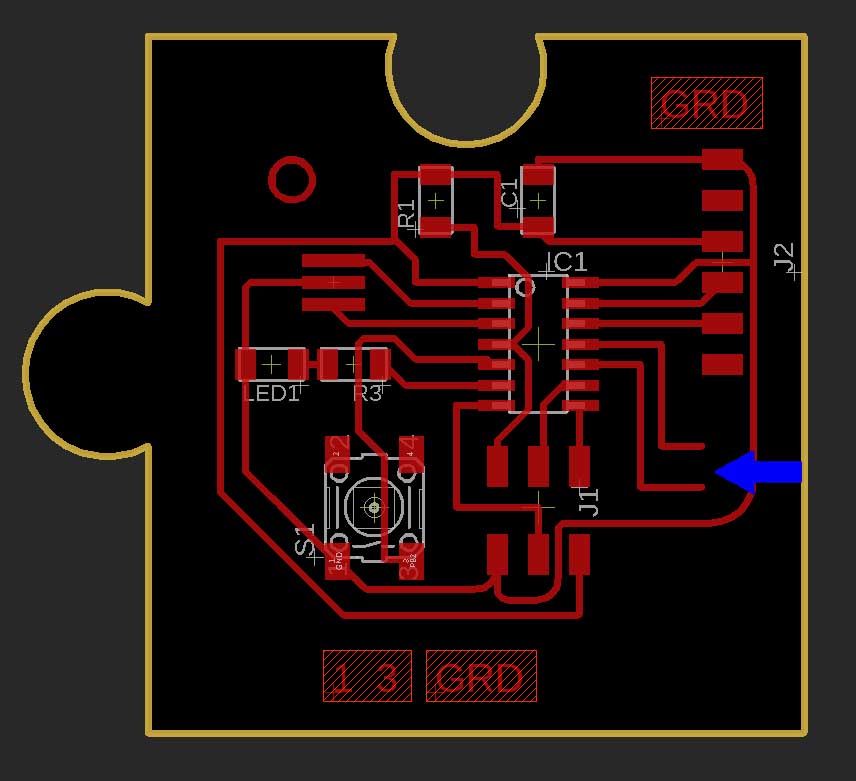
And we have the traces and cut PNG files.
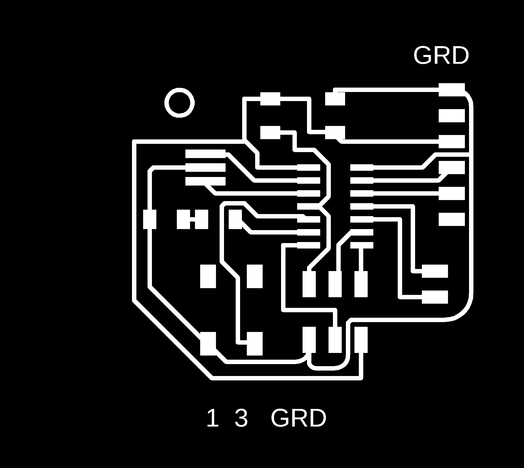
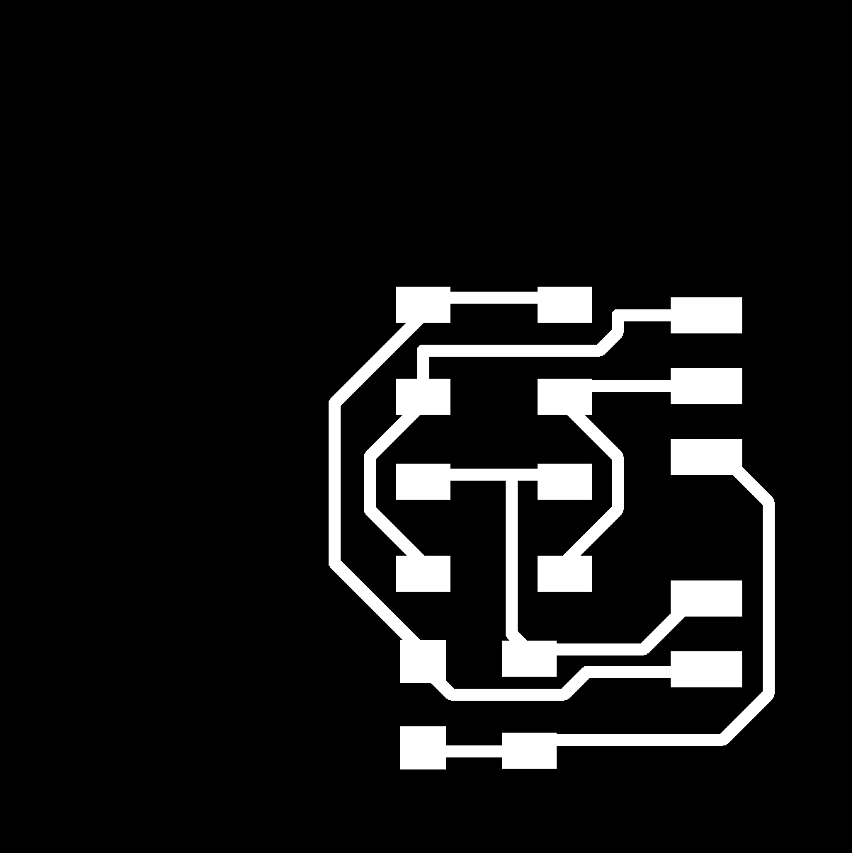
Traces:
As you can see I added the pads.
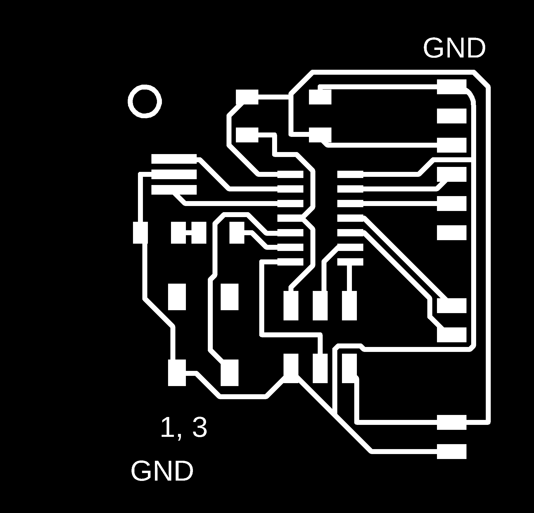
Cut:

Design input board:
Temperature sensor:
Datasheet:
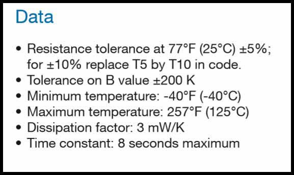
I want to use the temperature NTC-NHQ103B375T10, and the code describes that is a THERMISTOR NTC 10KOHM as you can see in the picture below.
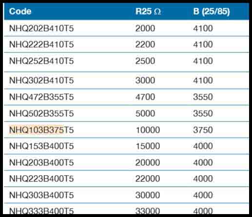
And the minimum and the maximum temperatures are -40C / 125C.
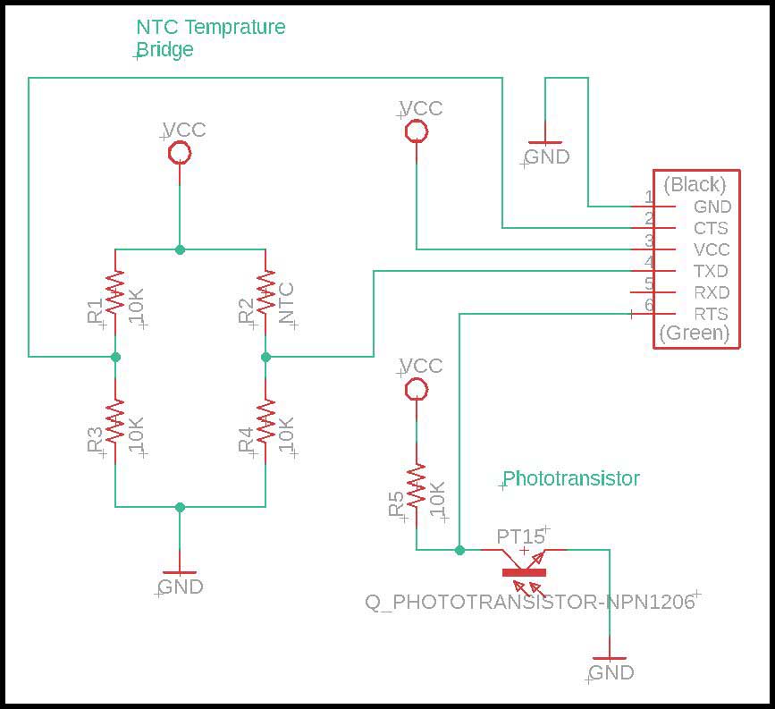
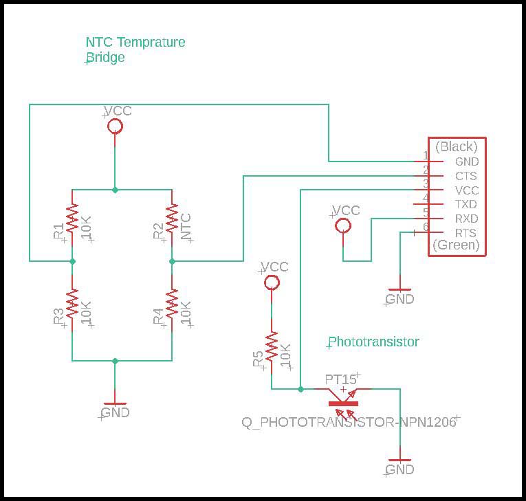
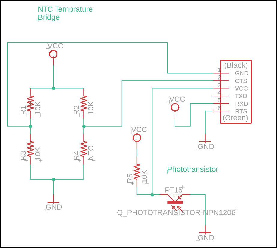
Design the Board:
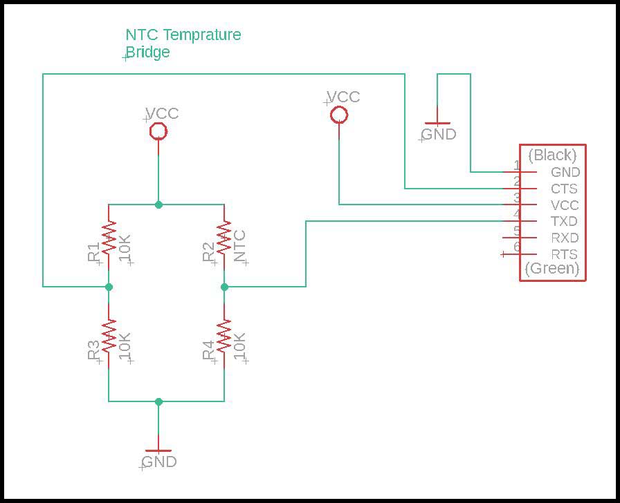
As you can see, I have used the FTDI jumpers to connect it to a main board; the new board.
And I have made a bridge resistor to measure the output of the temperature sensor, and from the data sheet I must put 10K ohm resistor to match the NTC resistance value.
The input will be connected to PA2 and PA3.
List of materials:
| Part Name | Footprint name | Quantity |
|---|---|---|
| Resistor 10KOHM | R1206FAB | 3 |
| CONN_06_FTDI-SMD-HEADER | 1X06SMD | 1 |
| NTC-NHQ103B375T10 | R1206FAB | 1 |
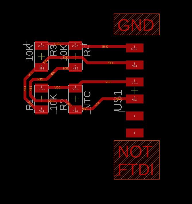
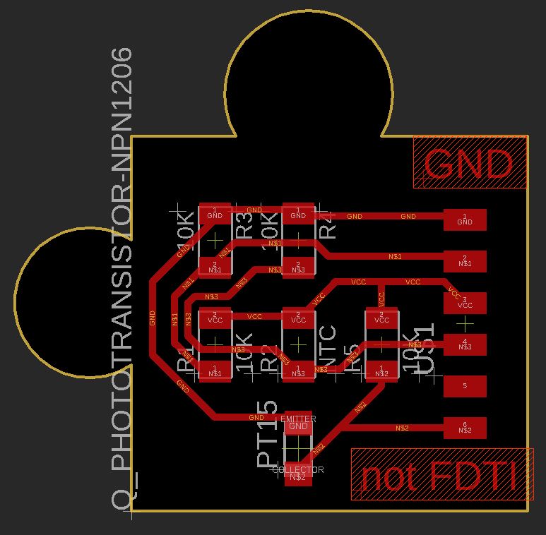
Board connection:
I have put a note that it is not a FTDI connection.
I have put value of width in Net classes to 16mil.
You can find it in Eagle

Edit tab ---> Net classes ---> Under the "Rules" tab
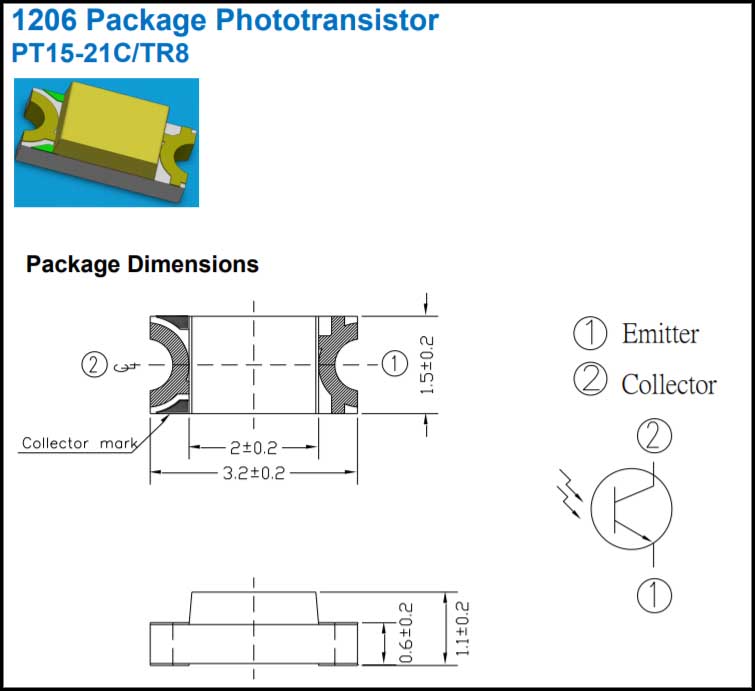
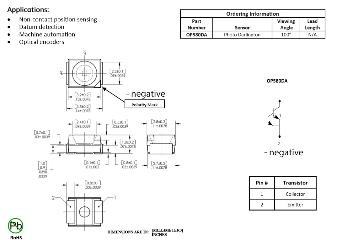
Optical Sensors - Phototransistors:
Data Sheet:
In this week also I want to use visible phototransistor PT15-21C/TR8, as you can see that the Collector mark indicate the Collector, and the other side is the Emitter.
Update, design the Board:
I connected voltage source to a 10KOHM resistor, and the resistor is connect to the Collector of the phototransistor, and Emitter is connected to a ground.
The output signal is connected to the RTS of the FTDI header.
The input will be connected to a free pin PA0 or PA1.
To update the file I had to export NetScript.
File --> Export ---> NetScript
Update, list of materials:
| Part Name | Footprint name | Quantity |
|---|---|---|
| Resistor 10KOHM | R1206FAB | 4 |
| CONN_06_FTDI-SMD-HEADER | 1X06SMD | 1 |
| NTC-NHQ103B375T10 | R1206FAB | 1 |
| Q_PHOTOTRANSISTOR-NPN1206 | OP1206 | 1 |
Update, Board connection:
The board will be updated after the exported the NetScript, and make shape of the other part of puzzle.
Redo the Boards:
As you can see in the Main Board I have made a mistake that I did not add a voltage source pin and a ground pin.
So I have reworked small parts to the design, and made matching puzzle size.
Main Board:
As you can see in the picture below that I have added a second FTDI header to connect a voltage source pin and a ground pin, as well as the pins PA2 and PA3.
In the picture below, I have re-routed the pins, as well as changed the interior size and shape.
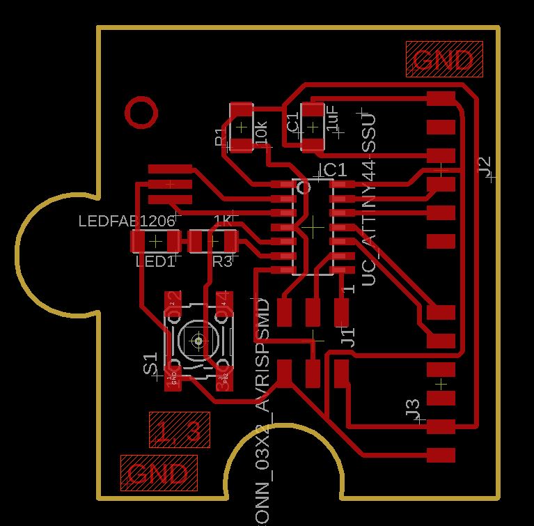
Compare the picture above and below, you notice that I have removed the extra unused two pads to not mix up with the FTDI header above.

Input Board:
I have rearranged the to more alike the main board, with the same sensors and components.
In the picture below, I have re-routed the pins, as well as changed the interior size and shape.
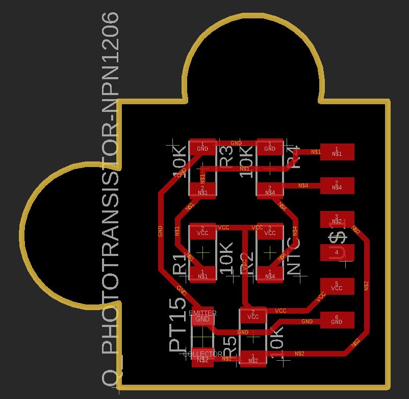
Compare the picture above and below, you notice that I have removed the extra unused one pad.

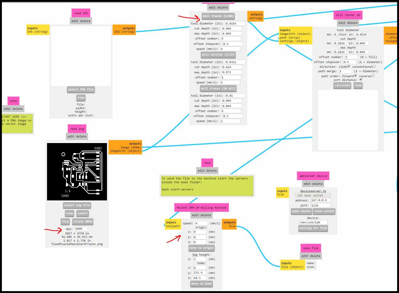
Generate the cutting files (.rml):
From mods, I have prepare the traces files, with reconfigure the origin (x,y,z) to zero, fixed the DPI to match the files’ DPI which is 1000, and the offset number for both is 5, then calculate.
The bit used is 1/64 inch.
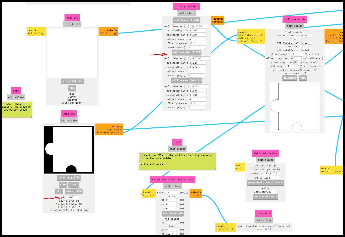
And also check the DPI for the outline, and use the 1/32 inch mill bit.
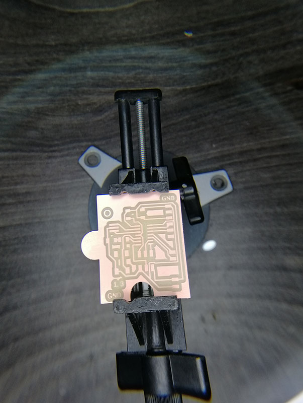
Milling the boards and soldering:
Hello board milling
Traces milling
Outline milling
Result
input board milling
With the same process as before.
Result
Mistake was made
After writing the code, I notice that the wirring was wrong, because we want to measure the the currrent and resistance values of the NTC from the voltage from the voltage devider, so I switch it back to the right loctaion.
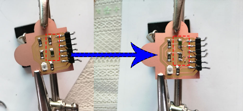
And updated the eagle files.
NTC code:
This is the code to read and calculate the temperature sensor.
#include <SoftwareSerial.h>

const int rxPin = 0;
const int txPin = 1;
const int led = 7;  // Make sure that is the program is running
int R25 = 10000;        // Value of NTC at 25 degrees
int B = 3750;           // From NTC data sheet
int Vref = 0;           // Refrence voltage
int Vntc = 0;           // NTC voltage
double Intc = 0;        // NTC current
double Rntc = 0;        // NTC resistnace
double T = 0;

SoftwareSerial mySerial(rxPin, txPin); // Rx pin A0, Tx pin A1

void setup() {

  // define pin modes for tx, rx:
  pinMode(rxPin, INPUT);
  pinMode(txPin, OUTPUT);

  // Define the LED on board
  pinMode (led, OUTPUT);

  // Initialize Serial
  mySerial.begin(9600);
  delay(3000); // To see the message when open the monitor via FTDI cable
}

void loop() {
  // put your main code here, to run repeatedly:

  Vref = analogRead(2);   // Reads refrence voltage
  Vntc = analogRead(3);   // reads NTC voltagee

  // Calculating the current

  Intc = (2 * Vref) - Vntc;

  // Calculating the NTC resistance value

  Rntc = Vntc / Intc;

  T = ( 1 / (log(Rntc / R25) / B) + (1 / 298.15)) - 273.15;

  mySerial.println(T);

  delay(500);

}
Problem
When compile the program there is not enough storage space, so not to build a new board I decided to use Processing to compile the data.
Sketch uses 4292 bytes (104%) of program storage space. Maximum is 4096 bytes.

Global variables use 144 bytes (56%) of dynamic memory, leaving 112 bytes for local variables. Maximum is 256 bytes.
Sketch too big; see http://www.arduino.cc/en/Guide/Troubleshooting#size for tips on reducing it.
Error compiling for board ATtiny24/44/84.
New code for ATtiny44:
The new code for the ATtiny:
#include <SoftwareSerial.h>

const int rxPin = 0;
const int txPin = 1;
const int led = 7;  // Make sure that is the program is running
int R25 = 10000;        // Value of NTC at 25 degrees
int B = 3750;           // From NTC data sheet
int Vref = 0;           // Refrence voltage
int Vntc = 0;           // NTC voltage
double Intc = 0;        // NTC current
double Rntc = 0;        // NTC resistnace
double T = 0;

SoftwareSerial mySerial(rxPin, txPin); // Rx pin A0, Tx pin A1

void setup() {

  // define pin modes for tx, rx:
  pinMode(rxPin, INPUT);
  pinMode(txPin, OUTPUT);

  // Define the LED on board
  pinMode (led, OUTPUT);

  // Initialize Serial
  mySerial.begin(9600);
  delay(3000); // To see the message when open the monitor via FTDI cable
}

void loop() {
  // put your main code here, to run repeatedly:
  pinMode (led, LOW);
  Vref = analogRead(2);   // Reads refrence voltage
  Vntc = analogRead(3);   // reads NTC voltagee

// Sending data to Processing

  mySerial.println(Vref);
  mySerial.println(',');
  mySerial.println(Vntc);
  mySerial.println('.');

  pinMode (led, HIGH);
  delay(500);
Processing code
The program gets its values from the ATtiny44, and process it thought Serial event to read the values, then solve it by math equations from Neil’s code.
B = 3750.0
R25 =  10000.0
T = 1.0/(log(R/R25)/B+(1/(25.0+273.15))) - 273.15
And I created a window shows the value of the temperature in text, with little animation of red rectangular changes as the temperature changes.
import processing.serial.*;
import java.awt.event.KeyEvent; // imports library for reading the data from the serial port

Serial arduino;                      // Create object from Serial class

int Vref = 0;           // Reference voltage
int Vntc = 0;           // NTC voltage
String data1="";        // string to hold input
String data2="";
int index=0;

int R25 = 10000;        // Value of NTC at 25 degrees
int B = 3750;           // From NTC data sheet
float Intc = 0;        // NTC current
float Rntc = 0;        // NTC resistance
float Tempratue = 0;


void setup() {
  size(400, 400);
  background(255);

  printArray(Serial.list());
  arduino = new Serial(this, Serial.list()[0], 9600);
  arduino.bufferUntil('n');
  arduino.clear();                   // Throw out the first reading, in case we started reading
  delay(6000);
}

void draw() {

  clear();
  background(255);
  delay(50);
  // declare rect base
  fill(0, 0, 255);   // R,G,B
  rect(100, 150, 200, 100);

  // declare rect value
  fill(255, 0, 0);   // R,G,B
  rect(100, 150, (Tempratue*3.5), 100);

  //Temperature in text
  textSize(32);
  fill(0, 102, 153);
  text("Tempratue="+Tempratue, 100, 100);

}

void serialEvent(Serial arduino) {

  data1=arduino.readStringUntil('n');

  if (data1!=null) {
    data1= data1.substring(0, data1.length()-1);
    index= data1.indexOf("r");
    data2= data1.substring(0, index);
    data1= data1.substring(index+1, data1.length());

    // converts the String variables into Integer
    Vref= int(data2);
    Vntc= int(data1);

    float Intc1 = ((2 * Vref) - Vntc); //10000
    Intc= Intc1/10000;

    // Calculating the NTC resistance value

    Rntc = Vntc / Intc ;
    // Temperature = (1/((log(Rntc/R25))/B)+(1/298.15)) - 273.15 ;  //- 273.15
    float Temperature1 = 1/((log(Rntc/R25))/B+(1/298.15)) ;  //- 273.15
    Temperature= Temperature1 - 273.15;

    // Uncomment to see the values in console of processing
    //printArray("Vref="+Vref);
    //printArray("Vntc="+Vntc);
    //printArray("Intc1="+ Intc1);
    //printArray("Intc="+ Intc);
    //printArray("Rntc="+ Rntc);
    //printArray("Tempratue="+ Tempratue);
  }
}
Challenges:
- I had to break down the equations into two parts like:
Temperature1 and TemperatureandIntc1 and Intc, because for some reasons it does not give the correct values when I put the whole equations. - I added
clear();to refresh the screen, because each time the screen is being updated, the text overlaps with each other.
Hero shoot video! NTC temperature sensor
Light sensor code:
First of all after I got back to the lab, the PT15 was not available in the lab, so I got a similar sensor silicon phototdarlington OP580DA.
This code was simple and straight forward, if there was no light affecting the Phototransistors, the LED on Hello board will give signal; LED ON.
Code:
I put the threshold value of analog read to 555.
const int SensorPin =2;
const int RedLED = 7;
int state;

void setup() {
  // put your setup code here, to run once:
pinMode(SensorPin, INPUT);
pinMode(RedLED, OUTPUT);
digitalWrite(RedLED, HIGH);
}

void loop() {
  // put your main code here, to run repeatedly:
 state= analogRead(SensorPin);
 delay(50);
if (state > 555)
{
  digitalWrite(RedLED, HIGH);
}else
{
  digitalWrite(RedLED, LOW);
}
delay(50);
}
Hero shoot video! NTC temperature sensor
TinkerCad:
I tested TinkerCad, and I have made a Phototransistor input, and shows the output in a LED.
Where in this program I made the phototransistor as an analog input, and the LED as an analog output.
And I have divided analog output of the LED by 6 to increase its threshold.
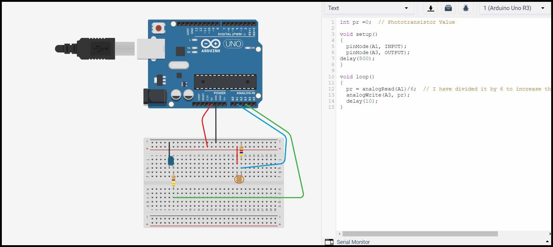
Code:
int pr =0;  // Phototransistor Value

void setup()
{
  pinMode(A1, INPUT);
  pinMode(A3, OUTPUT);
delay(500);
}

void loop()
{
  pr = analogRead(A1)/6;  // I have divided it by 6 to increase the threshold of the LED
  analogWrite(A3, pr);
  delay(10);
}