Embedded programming and electronics design:
Files to download
Program:
- Arduino.
- Eagle.
Electrical / Electronics Parts:
My project needs to control, output:
- 100 watt LED brightness and strobe frequency.
- Motor speed.
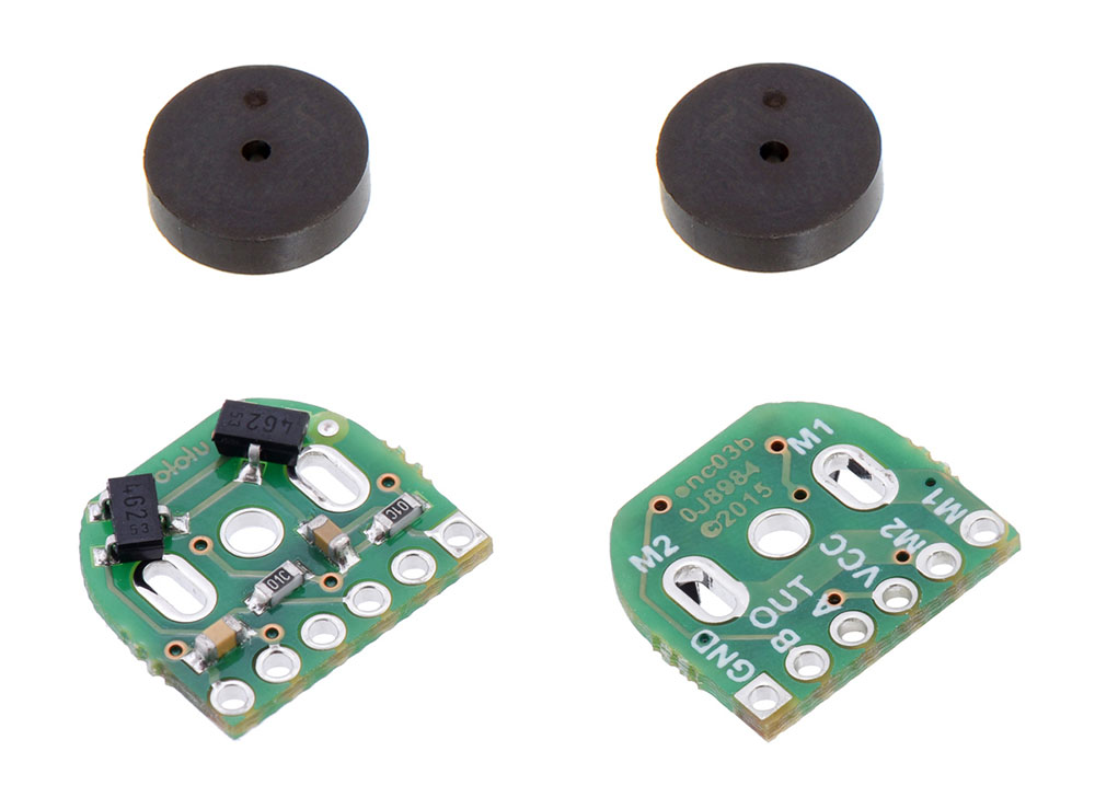
My input:
Magnetic Encoder; Hall sensor attached on the motor, for reading the rotational speed of the motor, where it reads 12 counts per revolution, or 12CPR.
Work concept:

I want to make a feedback loop to fine tune the speed of the motor [RPM], because the load that is mounted on the motor will affect the actual speed.
Embedded programming:
Tachometer:
I have used the this code before in Interface and application programming, to measure the speed of a DC motorized, and it written by InterlinkKnight.
And this program uses the interrupt on pin 2 for the Arduino/ATmega328p to measure the period between pulses using the micros() function.
/*
  Tachometer using micros

  On this sketch we are going to measure the period between pulses using the micros() function to get the RPM
  (Revolutions Per Minute) from a sensor on pin 2.
  This way of measuring RPM makes it accurate, responsive and versatile. No matter how fast or slow the loop is
  running, the reading accuracy is not going to be affected. Although, the faster you run the loop, the more amount
  of readings you are going to be able to display every second.

  It's coded in a way that the micros rollover doesn't create glitches every 71 minutes, so it can run forever
  without problems.

  We use an interrupt for the input so you have to choose pin 2 or 3 (for Arduino Uno/nano). In this example we
  use pin 2.

  This sketch was made for my video tutorial shown here: https://www.youtube.com/watch?v=u2uJMJWsfsg

  Made by InterlinkKnight
  Last update: 05/23/2019
*/

/////////////////
// Calibration://
/////////////////

const byte PulsesPerRevolution = 12;  // Set how many pulses there are on each revolution. Default: 2.

// If the period between pulses is too high, or even if the pulses stopped, then we would get stuck showing the
// last value instead of a 0. Because of this we are going to set a limit for the maximum period allowed.
// If the period is above this value, the RPM will show as 0.
// The higher the set value, the longer lag/delay will have to sense that pulses stopped, but it will allow readings
// at very low RPM.
// Setting a low value is going to allow the detection of stop situations faster, but it will prevent having low RPM readings.
// The unit is in microseconds.
const unsigned long ZeroTimeout = 100000;  // For high response time, a good value would be 100000.
// For reading very low RPM, a good value would be 300000.

// Calibration for smoothing RPM:
const byte numReadings = 20;  // Number of samples for smoothing. The higher, the more smoothing, but it's going to
// react slower to changes. 1 = no smoothing. Default: 2.


///////////////
// Variables://
///////////////

int countersend = 0;

volatile unsigned long LastTimeWeMeasured;  // Stores the last time we measured a pulse so we can calculate the period.
volatile unsigned long PeriodBetweenPulses = ZeroTimeout + 1000; // Stores the period between pulses in microseconds.
// It has a big number so it doesn't start with 0 which would be interpreted as a high frequency.
volatile unsigned long PeriodAverage = ZeroTimeout + 1000; // Stores the period between pulses in microseconds in total, if we are taking multiple pulses.
// It has a big number so it doesn't start with 0 which would be interpreted as a high frequency.
unsigned long FrequencyRaw;  // Calculated frequency, based on the period. This has a lot of extra decimals without the decimal point.
unsigned long FrequencyReal;  // Frequency without decimals.
unsigned long RPM;  // Raw RPM without any processing.
unsigned int PulseCounter = 1;  // Counts the amount of pulse readings we took so we can average multiple pulses before calculating the period.

unsigned long PeriodSum; // Stores the summation of all the periods to do the average.

unsigned long LastTimeCycleMeasure = LastTimeWeMeasured;  // Stores the last time we measure a pulse in that cycle.
// We need a variable with a value that is not going to be affected by the interrupt
// because we are going to do math and functions that are going to mess up if the values
// changes in the middle of the cycle.
unsigned long CurrentMicros = micros();  // Stores the micros in that cycle.
// We need a variable with a value that is not going to be affected by the interrupt
// because we are going to do math and functions that are going to mess up if the values
// changes in the middle of the cycle.

// We get the RPM by measuring the time between 2 or more pulses so the following will set how many pulses to
// take before calculating the RPM. 1 would be the minimum giving a result every pulse, which would feel very responsive
// even at very low speeds but also is going to be less accurate at higher speeds.
// With a value around 10 you will get a very accurate result at high speeds, but readings at lower speeds are going to be
// farther from eachother making it less "real time" at those speeds.
// There's a function that will set the value depending on the speed so this is done automatically.
unsigned int AmountOfReadings = 1;

unsigned int ZeroDebouncingExtra;  // Stores the extra value added to the ZeroTimeout to debounce it.
// The ZeroTimeout needs debouncing so when the value is close to the threshold it
// doesn't jump from 0 to the value. This extra value changes the threshold a little
// when we show a 0.

// Variables for smoothing tachometer:
unsigned long readings[numReadings];  // The input.
unsigned long readIndex;  // The index of the current reading.
unsigned long total;  // The running total.
unsigned long average;  // The RPM value after applying the smoothing.

void setup()  // Start of setup:
{

  Serial.begin(9600);  // Begin serial communication.
  attachInterrupt(digitalPinToInterrupt(2), Pulse_Event, RISING);  // Enable interruption pin 2 when going from LOW to HIGH.

  delay(1000);  // We sometimes take several readings of the period to average. Since we don't have any readings
  // stored we need a high enough value in micros() so if divided is not going to give negative values.
  // The delay allows the micros() to be high enough for the first few cycles.
  analogWrite(A1, 0);
}  // End of setup.


void loop()  // Start of loop:
{

  // The following is going to store the two values that might change in the middle of the cycle.
  // We are going to do math and functions with those values and they can create glitches if they change in the
  // middle of the cycle.
  LastTimeCycleMeasure = LastTimeWeMeasured;  // Store the LastTimeWeMeasured in a variable.
  CurrentMicros = micros();  // Store the micros() in a variable.

  // CurrentMicros should always be higher than LastTimeWeMeasured, but in rare occasions that's not true.
  // I'm not sure why this happens, but my solution is to compare both and if CurrentMicros is lower than
  // LastTimeCycleMeasure I set it as the CurrentMicros.
  // The need of fixing this is that we later use this information to see if pulses stopped.
  if (CurrentMicros < LastTimeCycleMeasure)
  {
    LastTimeCycleMeasure = CurrentMicros;
  }
  // Calculate the frequency:
  FrequencyRaw = 10000000000 / PeriodAverage;  // Calculate the frequency using the period between pulses.

  // Detect if pulses stopped or frequency is too low, so we can show 0 Frequency:
  if (PeriodBetweenPulses > ZeroTimeout - ZeroDebouncingExtra || CurrentMicros - LastTimeCycleMeasure > ZeroTimeout - ZeroDebouncingExtra)
  { // If the pulses are too far apart that we reached the timeout for zero:
    FrequencyRaw = 0;  // Set frequency as 0.
    ZeroDebouncingExtra = 2000;  // Change the threshold a little so it doesn't bounce.
  }
  else
  {
    ZeroDebouncingExtra = 0;  // Reset the threshold to the normal value so it doesn't bounce.
  }

  FrequencyReal = FrequencyRaw / 10000;  // Get frequency without decimals.
  // This is not used to calculate RPM but we remove the decimals just in case
  // you want to print it.

  // Calculate the RPM:
  RPM = FrequencyRaw / PulsesPerRevolution * 60;  // Frequency divided by amount of pulses per revolution multiply by
  // 60 seconds to get minutes.
  RPM = RPM / 10000;  // Remove the decimals.

  // Smoothing RPM:
  total = total - readings[readIndex];  // Advance to the next position in the array.
  readings[readIndex] = RPM;  // Takes the value that we are going to smooth.
  total = total + readings[readIndex];  // Add the reading to the total.
  readIndex = readIndex + 1;  // Advance to the next position in the array.

  if (readIndex >= numReadings)  // If we're at the end of the array:
  {
    readIndex = 0;  // Reset array index.
  }

  // Calculate the average:
  average = total / numReadings;  // The average value it's the smoothed result.

  // Print information on the serial monitor:
  // Comment this section if you have a display and you don't need to monitor the values on the serial monitor.
  // This is because disabling this section would make the loop run faster.
  //  int processing = map(average, 0 , 10000, 0, 255);
  countersend++;
  if (countersend = 5000)
  {
    int averageX = (round(average/10))*10;
    Serial.print(averageX);
    Serial.print(".");
    countersend = 0;
  }
}  // End of loop.

void Pulse_Event()  // The interrupt runs this to calculate the period between pulses:
{
  PeriodBetweenPulses = micros() - LastTimeWeMeasured;  // Current "micros" minus the old "micros" when the last pulse happens.
  // This will result with the period (microseconds) between both pulses.
  // The way is made, the overflow of the "micros" is not going to cause any issue.

  LastTimeWeMeasured = micros();  // Stores the current micros so the next time we have a pulse we would have something to compare with.

  if (PulseCounter >= AmountOfReadings) // If counter for amount of readings reach the set limit:
  {
    PeriodAverage = PeriodSum / AmountOfReadings;  // Calculate the final period dividing the sum of all readings by the
    // amount of readings to get the average.
    PulseCounter = 1;  // Reset the counter to start over. The reset value is 1 because its the minimum setting allowed (1 reading).
    PeriodSum = PeriodBetweenPulses;  // Reset PeriodSum to start a new averaging operation.

    // Change the amount of readings depending on the period between pulses.
    // To be very responsive, ideally we should read every pulse. The problem is that at higher speeds the period gets
    // too low decreasing the accuracy. To get more accurate readings at higher speeds we should get multiple pulses and
    // average the period, but if we do that at lower speeds then we would have readings too far apart (laggy or sluggish).
    // To have both advantages at different speeds, we will change the amount of readings depending on the period between pulses.
    // Remap period to the amount of readings:
    int RemapedAmountOfReadings = map(PeriodBetweenPulses, 40000, 5000, 1, 10);  // Remap the period range to the reading range.
    // 1st value is what are we going to remap. In this case is the PeriodBetweenPulses.
    // 2nd value is the period value when we are going to have only 1 reading. The higher it is, the lower RPM has to be to reach 1 reading.
    // 3rd value is the period value when we are going to have 10 readings. The higher it is, the lower RPM has to be to reach 10 readings.
    // 4th and 5th values are the amount of readings range.
    RemapedAmountOfReadings = constrain(RemapedAmountOfReadings, 1, 10);  // Constrain the value so it doesn't go below or above the limits.
    AmountOfReadings = RemapedAmountOfReadings;  // Set amount of readings as the remaped value.
  }
  else
  {
    PulseCounter++;  // Increase the counter for amount of readings by 1.
    PeriodSum = PeriodSum + PeriodBetweenPulses;  // Add the periods so later we can average.
  }
}  // End of Pulse_Event.
Pulse width modulation PWM:
I will use this library PWM.h to control the LED strobes by changing the frequency/length of the duty cycle and the duty cycle itself; by controlling the ON/OFF values as a percentage, from 0-255 on the pins shown on bellow.
| pin | Timer used |
|---|---|
| 9,10 | Timer1 |
| 3, 11 | Timer2 |
Functions:
And here is some of the commands needs to be explained:
-
SetPinFrequencySafe(): set the frequency of selected pin without usingTimer0. -
SetPinFrequency(): set the frequency in Hz of selected pin, and it will affect the time functions like;delay(),micros() -
InitTimersSafe(): Call the function to start, usually it put in thesetup void(), without affecting theTimer0 -
pwmWrite(): Change the ON/OFF percentage, example:pwmWrite(pin, 127)and it will give PWM of 50% value.
Controlling LED:
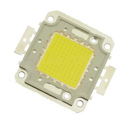
From John Edmark’s instructables, he explains what is the optimal why to control the light:
You can also make your own LED strobe light, controlled by an Arduino board. Note that it’s not enough to simply have the light flashing at 30fps, with the on-times and off-times being equal in length; the on-times must be no more than 0.5% of the off-time in order to properly freeze the spinning sculpture. This means that the apparent brightness of the light will be only 0.5% (1/200th) of what it actually is. So the LED has to be very powerful. I used this 100W LED and this reflector and it is bright enough (especially when over-driven by a factor of 2-5, which can be done without harming the LED since it is on for such a brief periods).
And from that we need to fix the strobes to 30Hz, and with PWM of 0.5% or 1 to 5 from 255.
Controlling the motor:
Using the same function, we don’t need to change the frequency, but just use the function pwmWrite() to control the motor speed.
And from the values from the PID controlling, By defining the setpoint, I get my values using the PIDLibrary, and put my output to the pwmWrite().
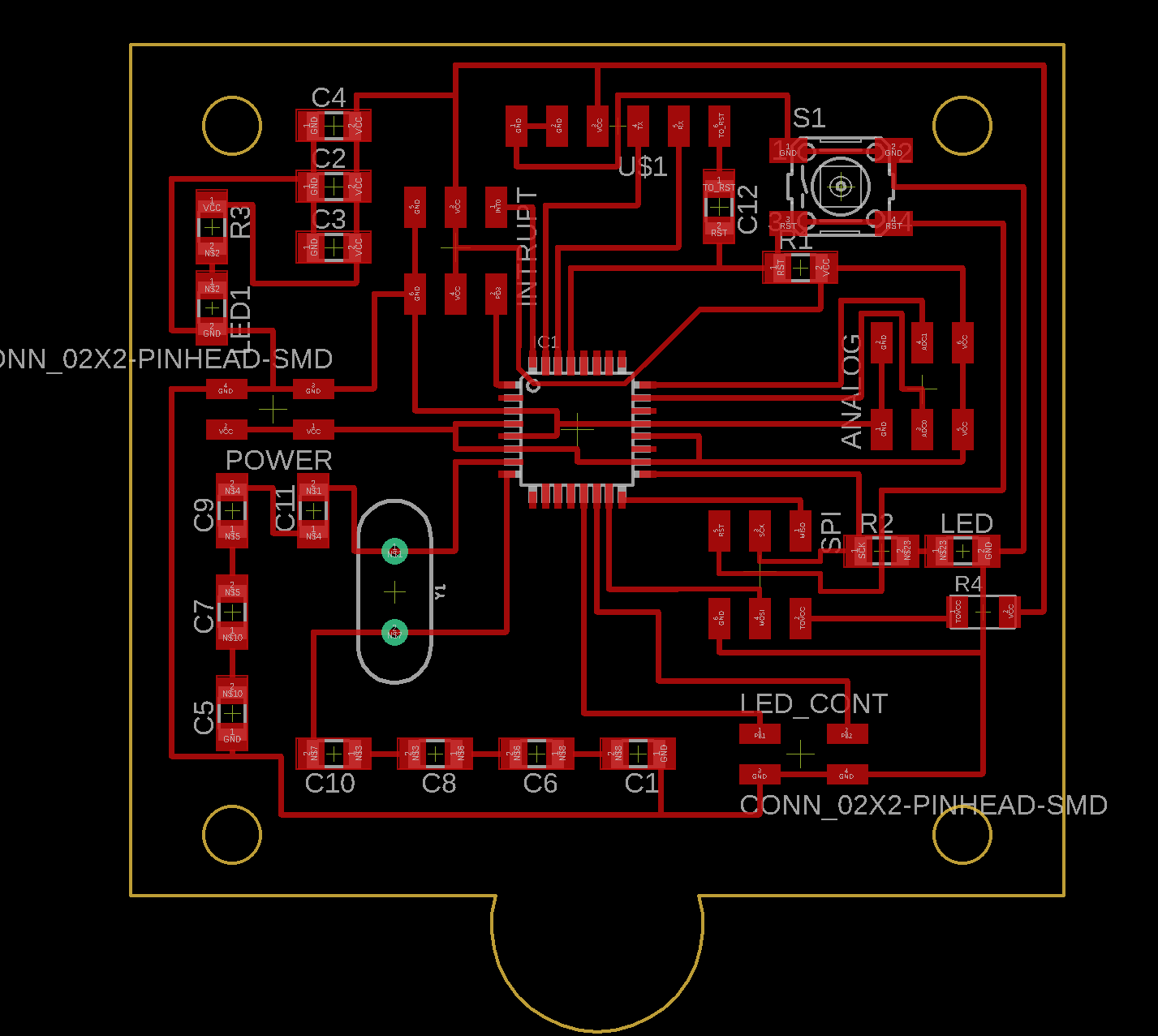
Electronics design:
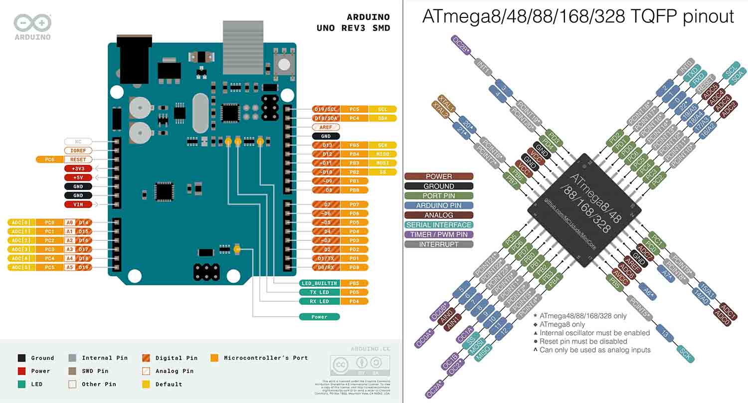
Because I am using three Timers to control the LED and motor, and reading the Magnetic Encoder (Tachometer), it is the best to use ATmega328p, while the ATtiny microcontrollers only two Timers max.
Microcontroller:
After doing some testing on the Arduino UNO, I only used the pins that I need, and I have added some other pins as a backup or add other components inn the future.
And have used 16MHz crystal with 22pF series of capacitors connected with each pin into the ground, just to make sure that the PWM.h library works properly because the Arduino UNO has also 16MHz crystal on it.
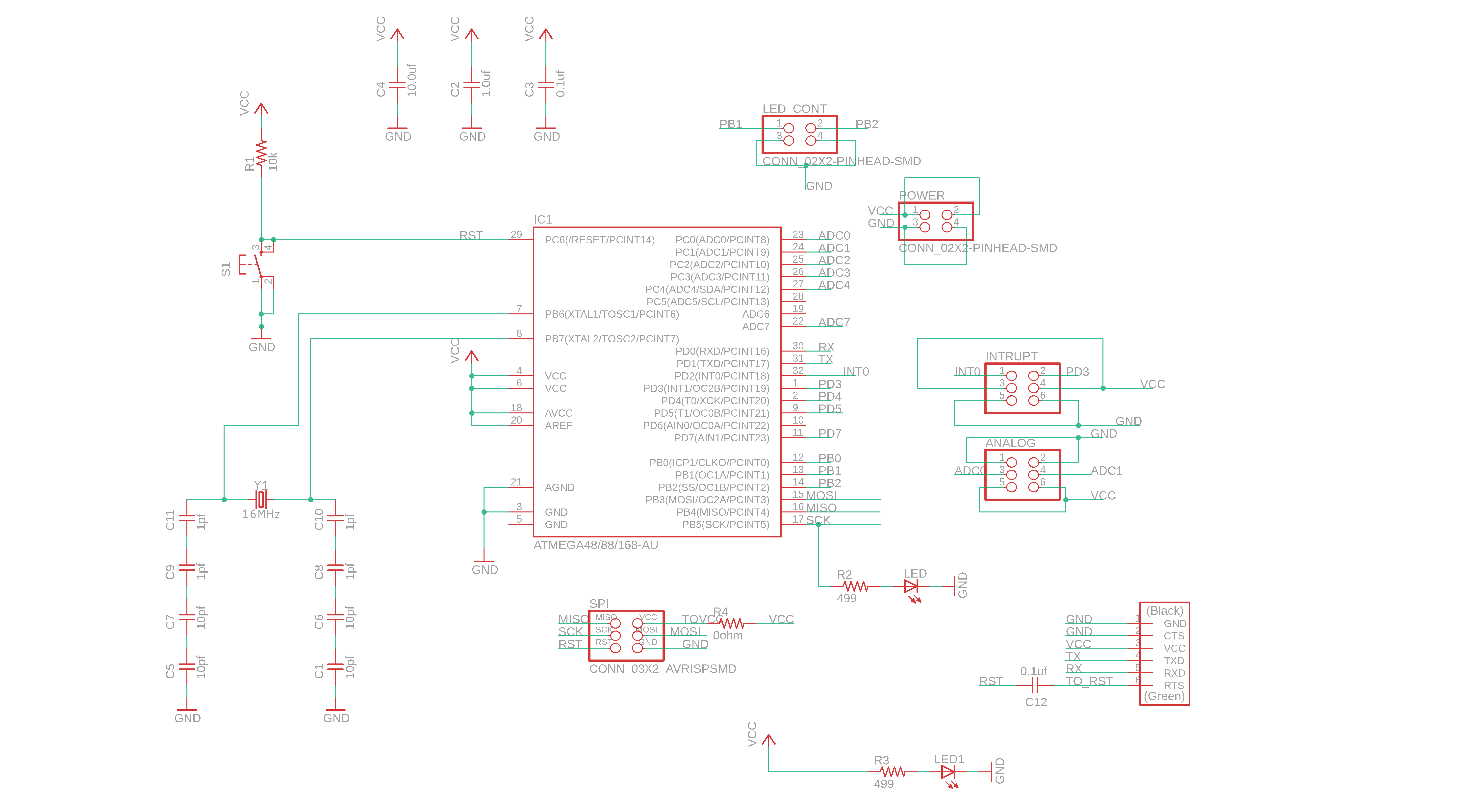
Pin description:
| Pin | Usage |
|---|---|
| PD2 | Interrupt to read magnetic encoder |
| PB1 | TIMER1 PWM pin to control the LED |
| PB2 | TIMER1 PWM backup pin |
| PD3 | TIMER2 PWM to control the motor |
| ADC0 | For analog read/write |
| ADC1 | For analog read/write |
| PB3 | MOSI; programming the controller using USBtinyISP |
| PB4 | MOSI; programming the controller using USBtinyISP |
| PB5 | SCK; programming the controller using USBtinyISP |
| PC6 | RST; programming the controller using USBtinyISP |
| PD0 | RX, receive pin for communication |
| PD1 | TX, receive pin for communication |
| PB6/PB7 | To connect to crystal/ resonator |
B.O.M:
| Qty | Value | Device | Package | Parts | Description |
|---|---|---|---|---|---|
| 1 | — | 06MM_SWITCH6MM_SWITCH | 6MM_SWITCH | S1 | OMRON SWITCH |
| 2 | — | CONN_03X2-PINHEAD-SMD | 2X03SMD | ANALOG, INTRUPT | PIN HEADER |
| 2 | — | LED1206 | 1206 | LED, LED1 | Blue LED |
| 2 | 0.1uf | UNPOLARIZED_CAPACITOR1206 | 1206 | C3, C12 | unpolarized_capacitor |
| 1 | 0ohm | R1206FAB | R1206FAB | R4 | Resistor (US Symbol) |
| 1 | 1.0uf | UNPOLARIZED_CAPACITOR1206 | 1206 | C2 | unpolarized_capacitor |
| 1 | 10.0uf | UNPOLARIZED_CAPACITOR1206 | 1206 | C4 | unpolarized_capacitor |
| 1 | 10k | RESISTOR1206 | 1206 | R1 | Resistor |
| 4 | 10pf | UNPOLARIZED_CAPACITOR1206 | 1206 | C1, C5, C6, C7 | unpolarized_capacitor |
| 1 | 16MHz | CRYSTAL-16MHZPTH-HC49US | HC49US | Y1 | 16MHz Crystal |
| 4 | 1pf | UNPOLARIZED_CAPACITOR1206 | 1206 | C8, C9, C10, C11 | unpolarized_capacitor |
| 2 | 499 | RESISTOR1206 | 1206 | R2, R3 | Resistor |
| 1 | ATmega328p | ATmega328p | TQFP32-08 | IC1 | Microcontroller |
| 2 | CONN_02X2-PINHEAD-SMD | CONN_02X2-PINHEAD-SMD | 2X02SMD | LED_CONT, POWER | Pinheader |
| 1 | CONN_03X2_AVRISPSMD | CONN_03X2_AVRISPSMD | 2X03SMD | SPI | Pinheader |
| 1 | CONN_06_FTDI-SMD-HEADER | CONN_06_FTDI-SMD-HEADER | 1X06SMD | U$1 | Pinheader |
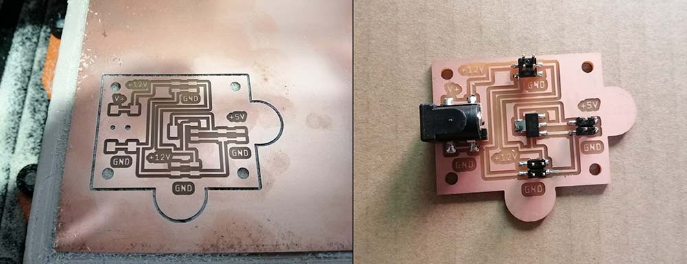
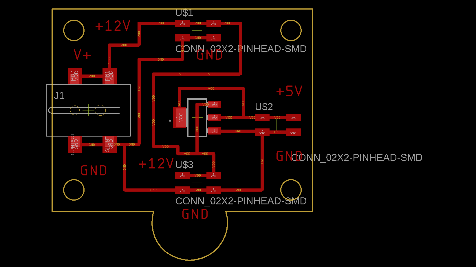
Power supply board:
I made a power supply board with a voltage regulator and connecter jack to provide the LED and the motor with 12 volts, and the microcontroller with 5 volts.
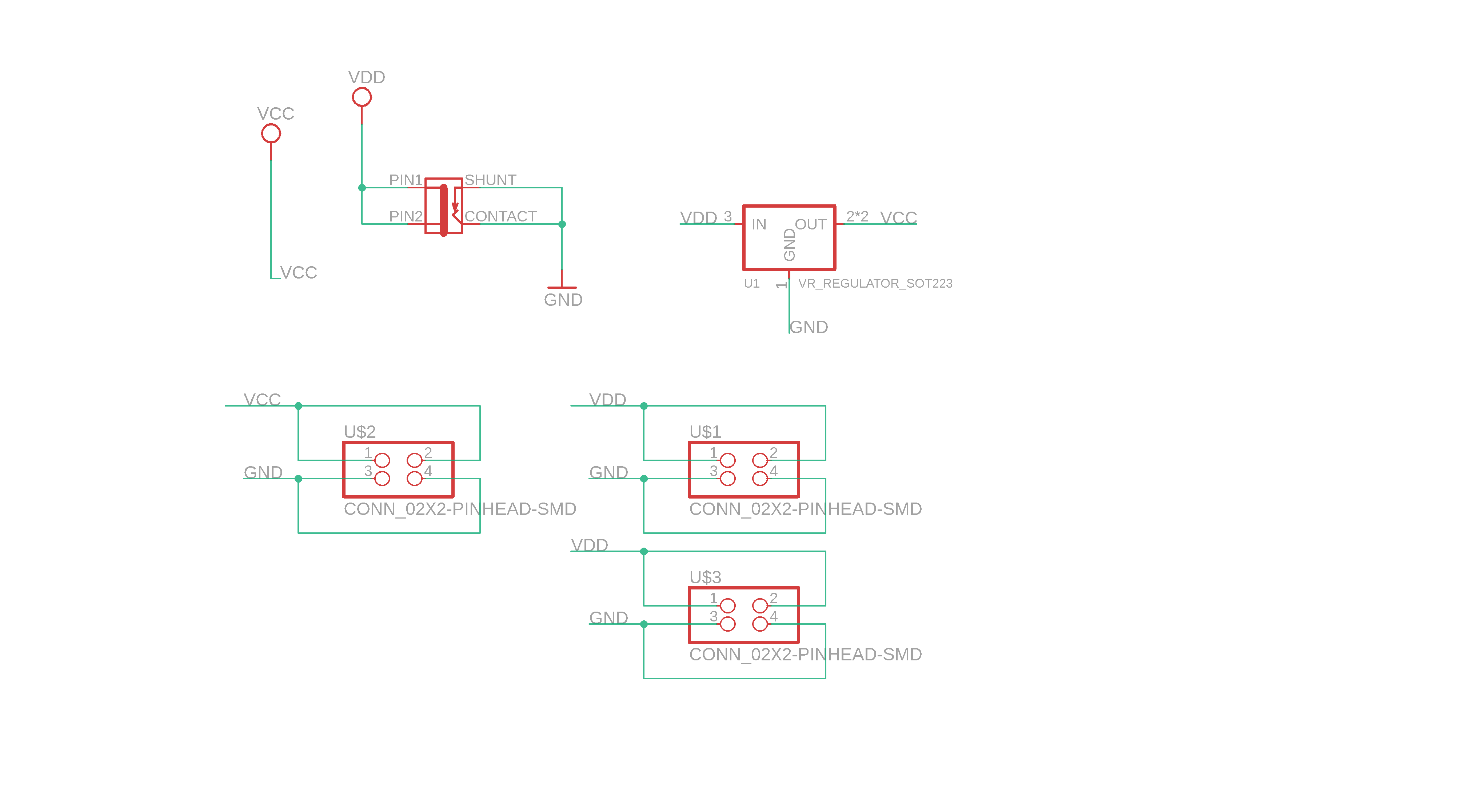
B.O.M.:
| Qty | Device | Package |
|---|---|---|
| 3 | CONN_02X2-PINHEAD-SMD | 2X02SMD |
| 1 | CONN_JACK-2.1MM | PJ-002AH-SMT |
| 1 | VR_REGULATOR_SOT223 | SOT223 |
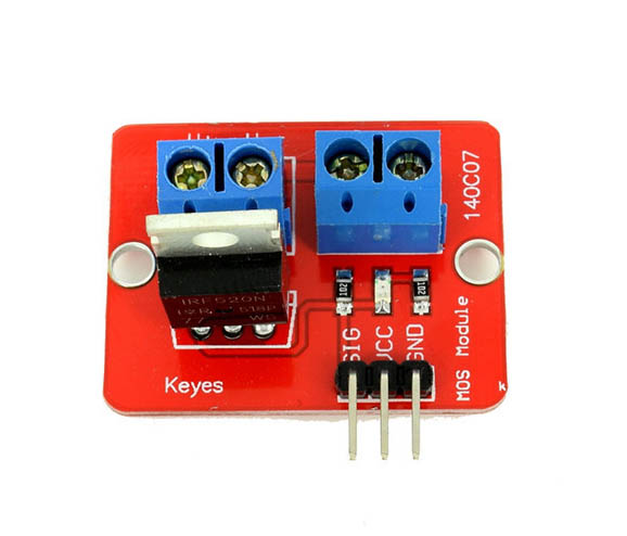
Driver IRF520 MOSFET:
Why I choose this MOSFET as a driver?, from the datasheet:
Features:
- Dynamic dV/dt Rating.
- Fast Switching.
- Simple Drive Requirements.
- It has a low gate threshold voltage of only 4V, this means that the MOSFET can be turned on even with 5V from the GPIO pin of microcontrollers.
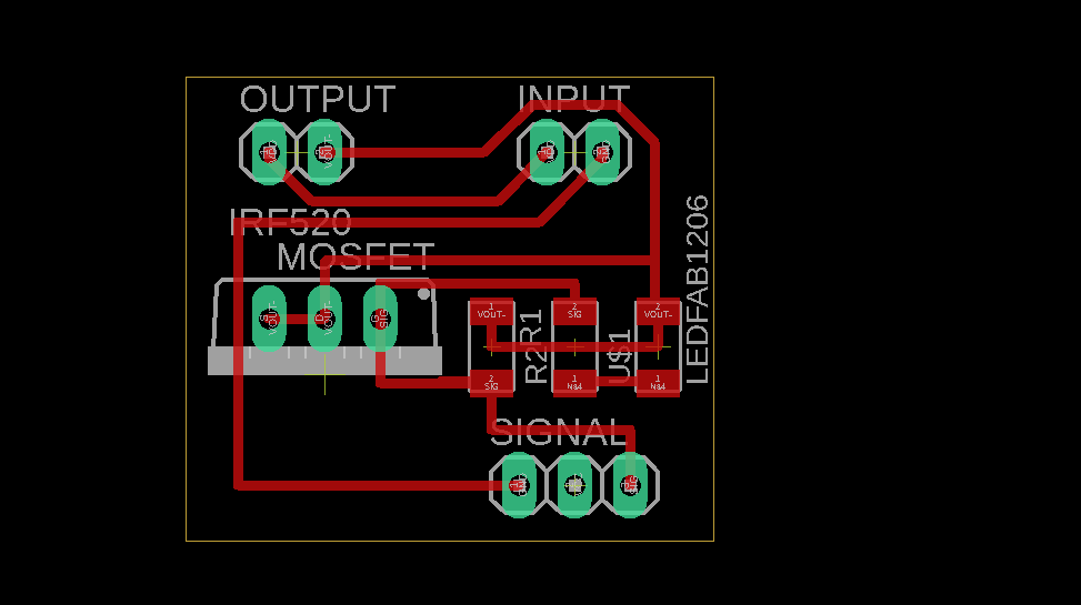
Initially I re-drawn the circuit in Eagle, but I have found a cheap driver module, while other stores sell just the MOSFET four times the price.
This module can drive the 100watt LED, and also the it can drive the motor on one direction.
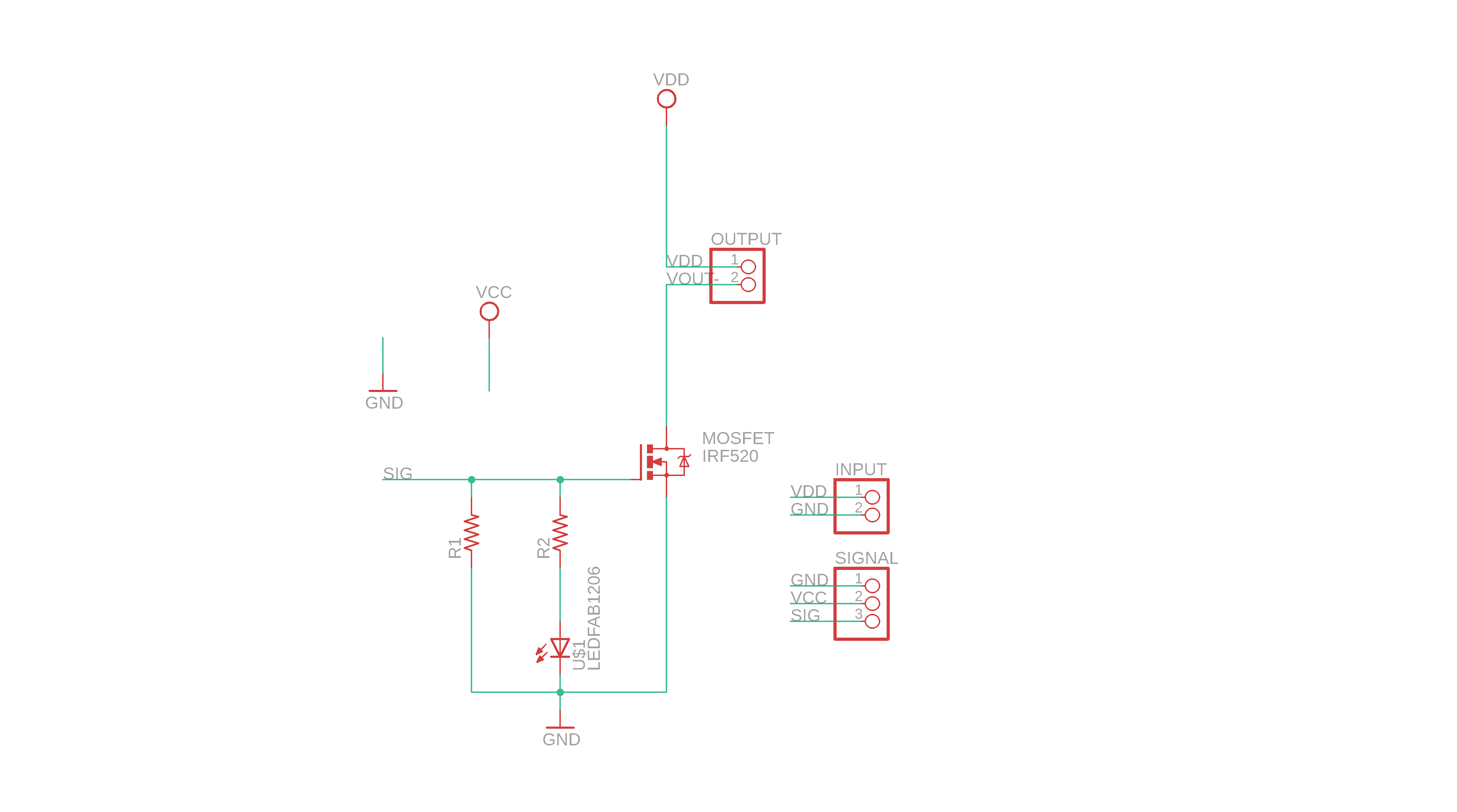
B.O.M.:
| Qty | Value | Device | Package | Parts | Description |
|---|---|---|---|---|---|
| 2 | — | PINHD-1X2 | 01X02 | INPUT, OUTPUT | PIN HEADER |
| 1 | — | PINHD-1X3 | 01X03 | SIGNAL | PIN HEADER |
| 2 | 1K | R1206FAB | R1206FAB | R1, R2 | Resistor (US Symbol) |
| 1 | IRF520 | IRF520 | TO220BV | MOSFET | HEXFET Power MOSFET |
| 1 | LEDFAB1206 | LEDFAB1206 | LED1206FAB | U$1 | LED |
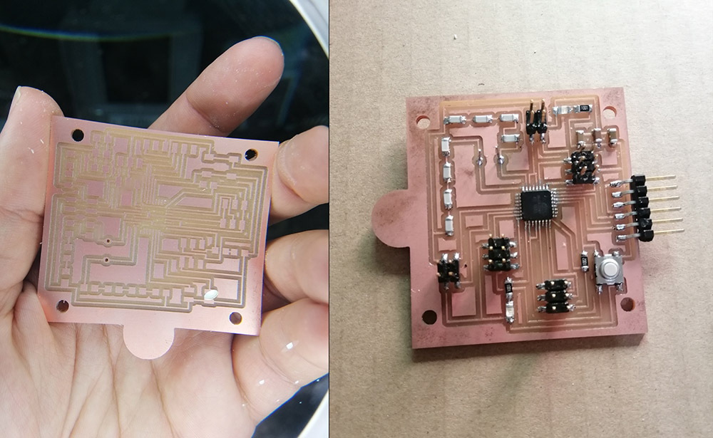
Process of making:
Milling the boards:
Soldering the boards:
Hero shoot!!
Microcontroller board:
Power supply board: