During the fourth session dated February 6 2019 of the "Fab Academy Program 2019" we were introduced to the Vinyl and Laser cutters. The objective was to learn how to use these machines.
Our Group assignment is to characterize our laser cutter(model, functionality), and make test part(s) that vary cutting settings and dimensions (find the kerf of the materials).
And as individual assignment we should cut something on the vinyl cutter and document it
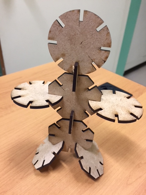
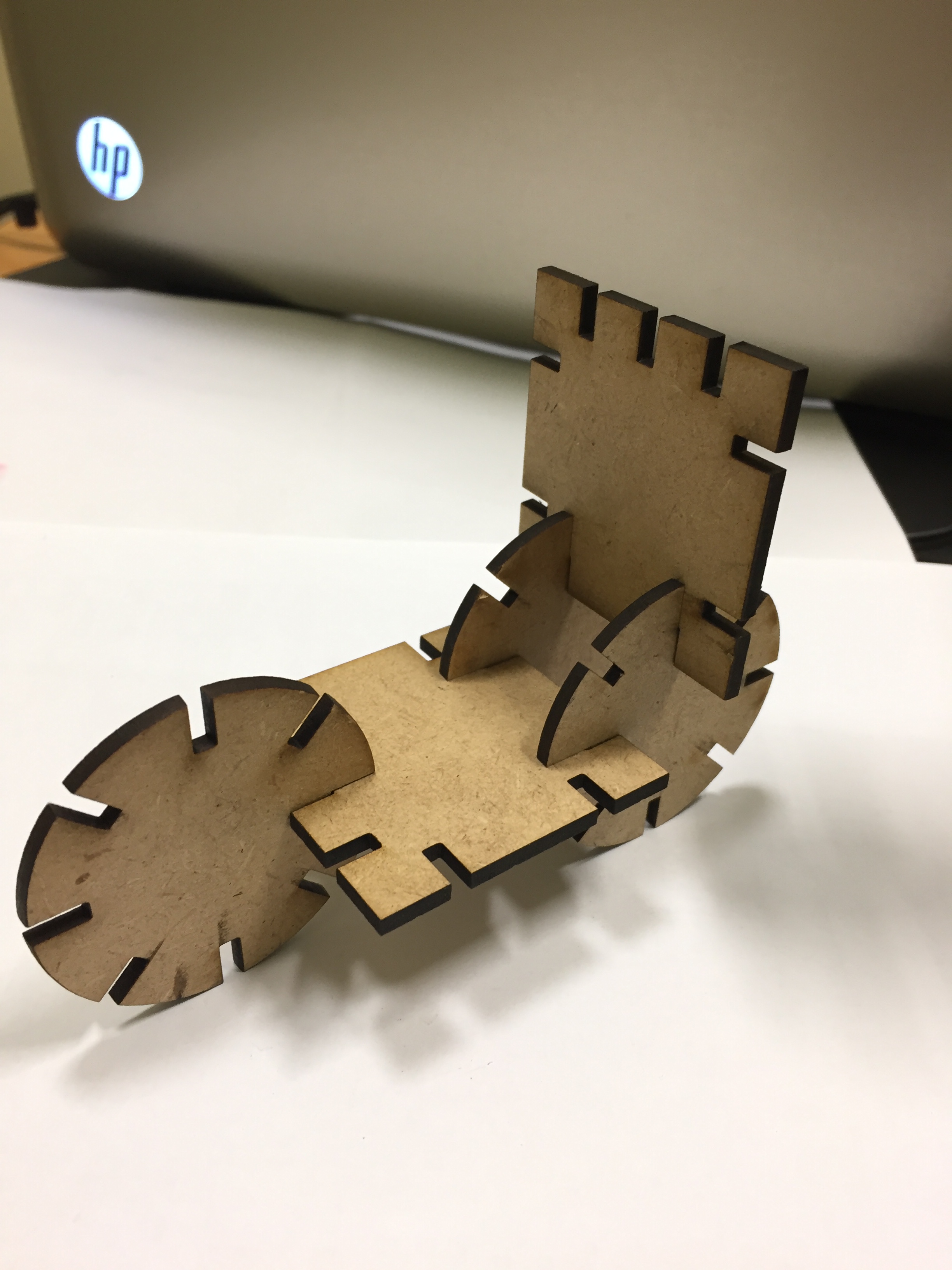
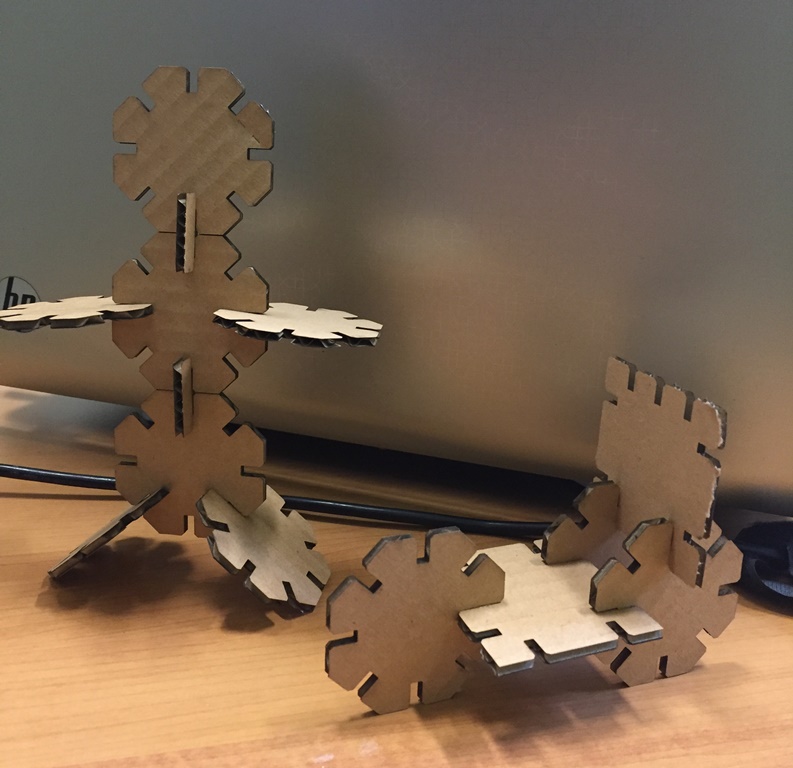
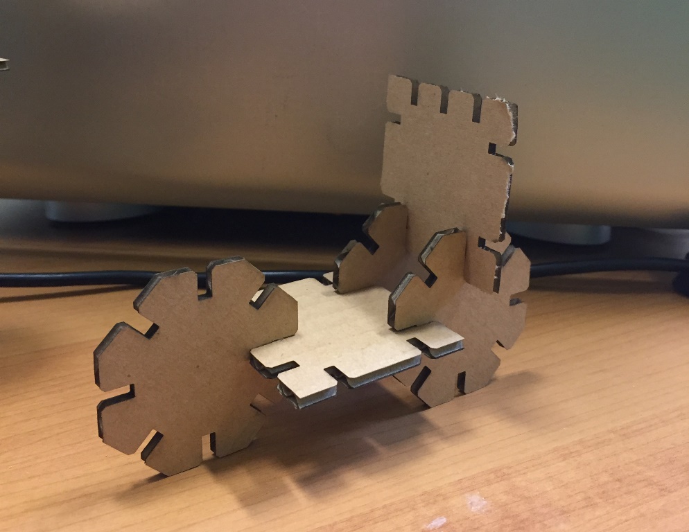
and design, make and document a parametric press-fit construction kit, accounting for the laser cutter kerf, which can be assembled in multiple ways.
There are many different technologies available in the market that are used to cut into various material, and that are computer controlled. Among those computers controlled cutting technologies are the Vinyl Cutters and the Laser Cutter.
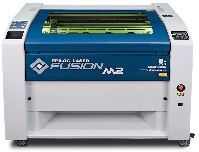
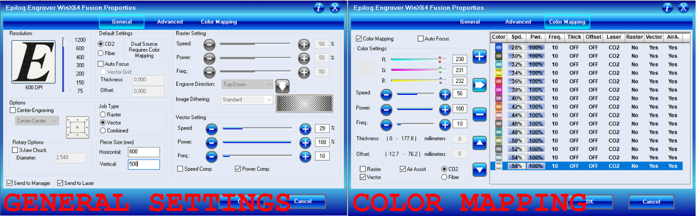
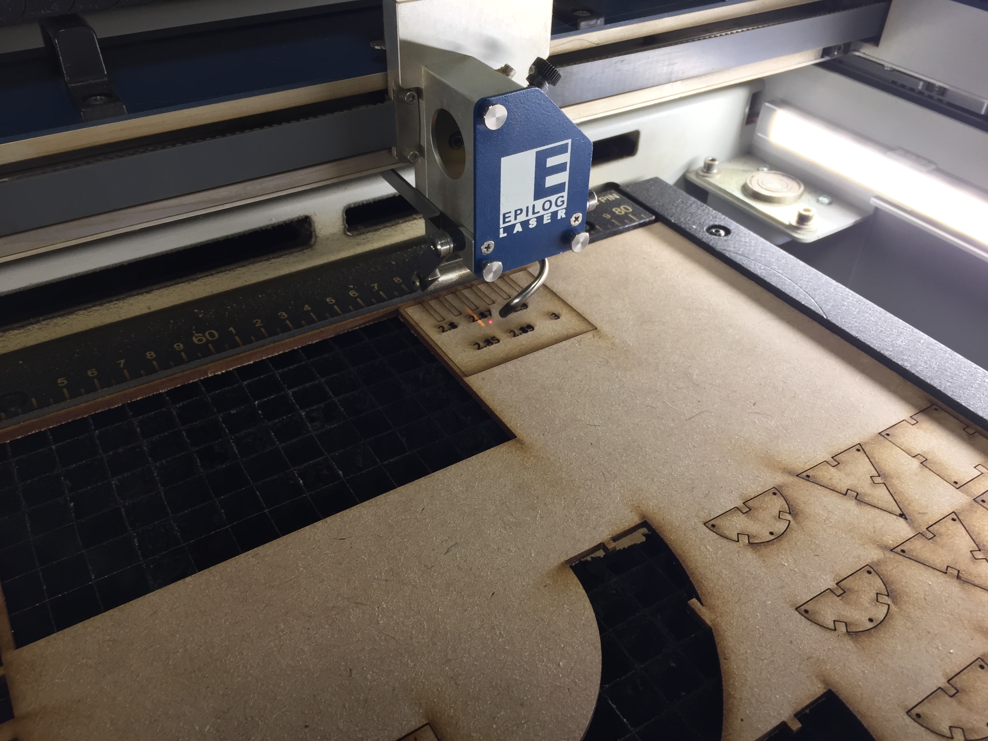
Characterize our Laser Cutter EPILOG FUSION M2:
Laser Cutting is a non-contact process which utilizes a laser to cut materials, resulting in high quality, dimensionally accurate cuts. It is typically used for industrial manufacturing applications, but is also starting to be used by schools, small businesses, and hobbyists. The process works by directing the laser beam through a nozzle to the work piece. A combination of heat and pressure creates the cutting action. The material melts, burns, vaporizes, or is blown away by a jet of gas, leaving an edge with a high-quality surface finish.
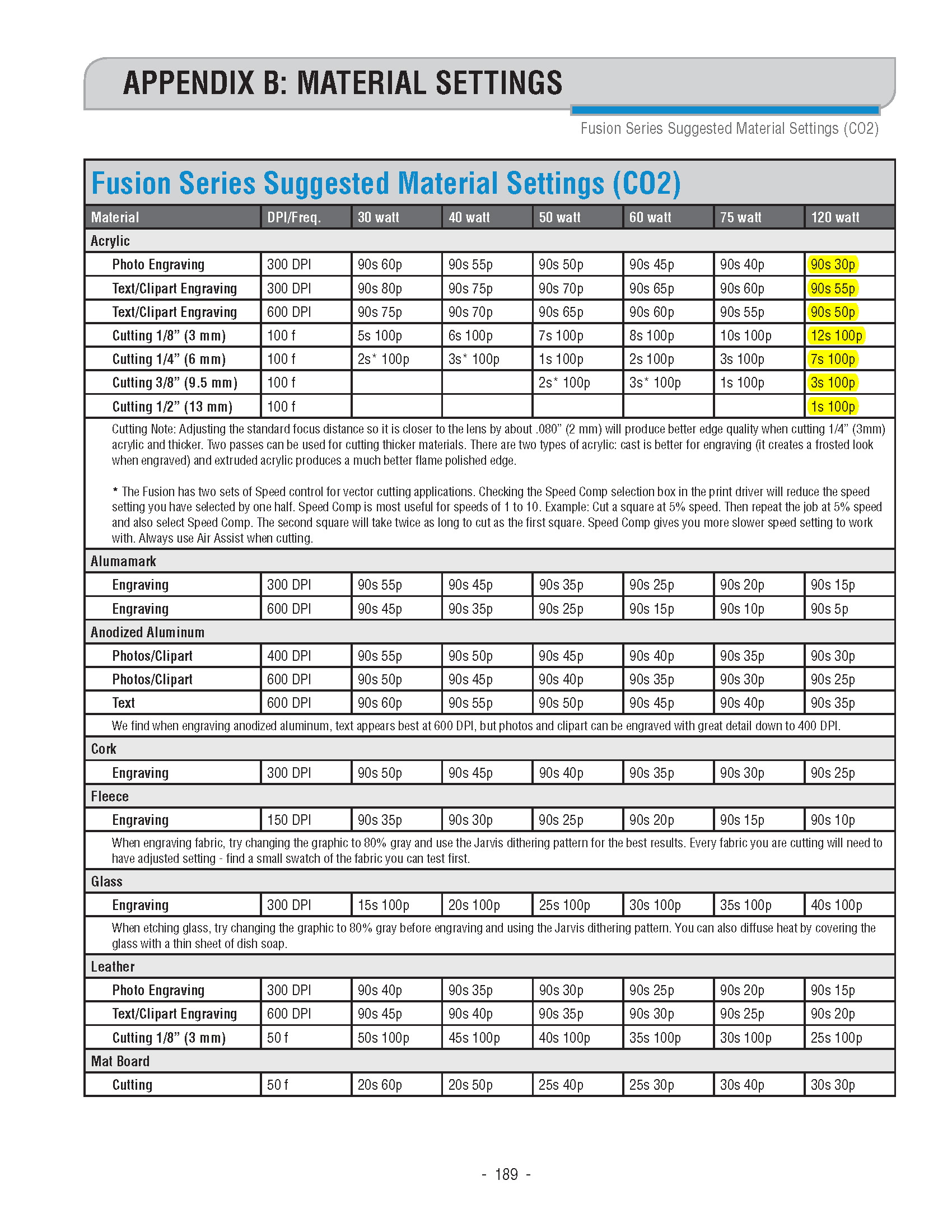
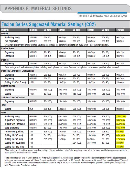
The materials and their according power, speed and frequency are listed in the below tables:
Available Material:
3mm MDF which happened to be of 3.17 mm after measuring it accurately with the caliper.
For cutting the wood, the power of the laser cutter should always be 100; the speed varies according to the thickness as mentioned in the above table. We calculated the kerf of our laser cutter via two types of tests.
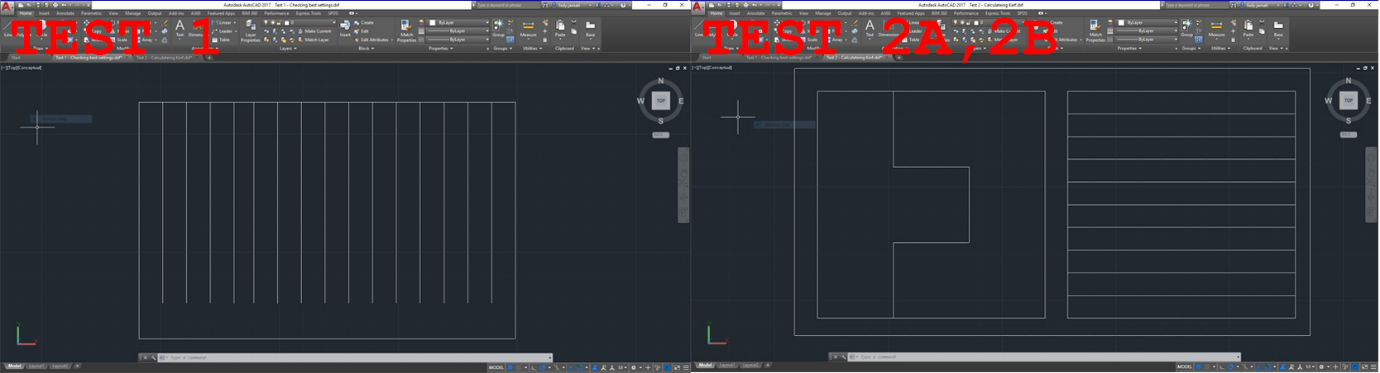
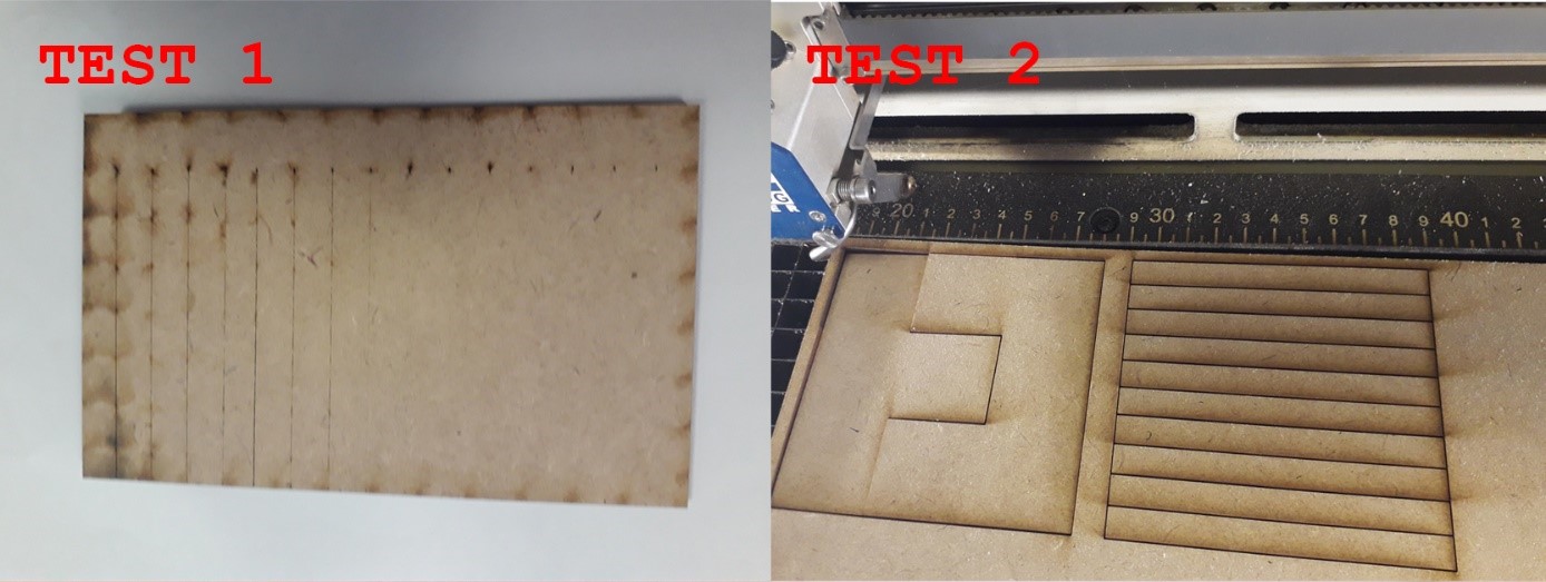
First test:
Objective: Select the best cutting setting in terms of speed, power, and frequency. In our case, for wood, power and frequency are known. Cutting speed needs to be determined
Method: Cut multiple lines with different speed settings around the reference speed provided by the manufacturer's specifications. Observe by eye at which speed the material is fully cut. The first fully cut line should be the thinner cut, thus the smaller kerf.
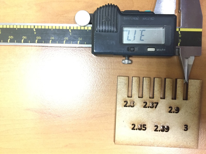
Second test:
Objective: Measure the kerf for the setting previously selected.
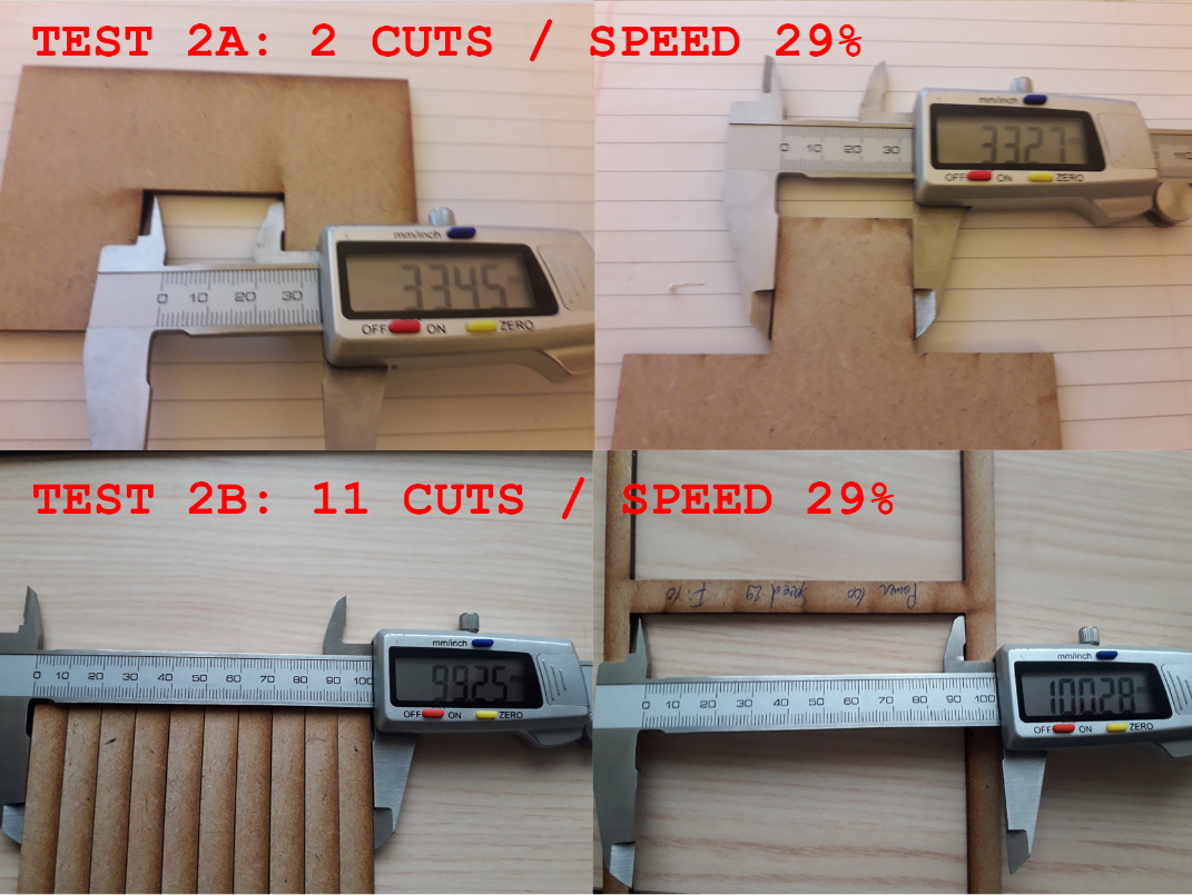
Method: Cut one or multiple segments with the same setting. Measure the length of the outer frame, measure the length of the adjacent cut segments, divide the difference by the number of cuts. The result is an estimation of the kerf. We made two tests with different layouts to get an average.
How to perform the tests:
Test Results:
First test: The best cut appears to be between 28 and 30% speed.
Second test:
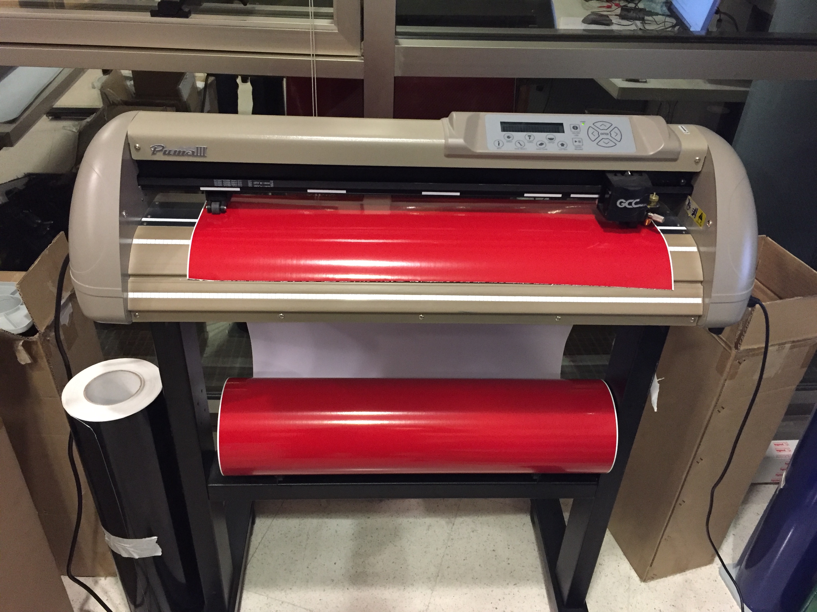
Vinyl cutters are computer controlled machines, which resemble to mini printers. The cutting machine uses a sharp computer controlled blade, which is used to cut small shapes and letters from sheets of colored vinyl. This way, labels and symbols are made from vinyl cutters. The entire operation is very simple, because shapes are cut out from vinyl, which can then be stuck on any surface.
Powered by a digitally controlled servo system, the Puma III produces eye-catching graphics with up to 23.62 ips (600mm/sec) cutting speed, 400g of cutting force, and five meters (16.4 feet) of tracking ability.
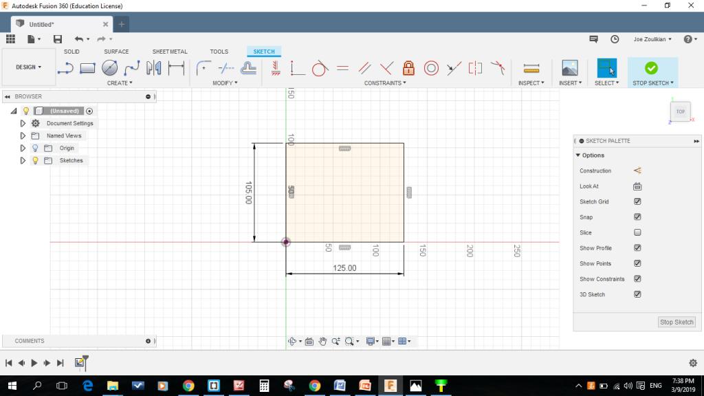
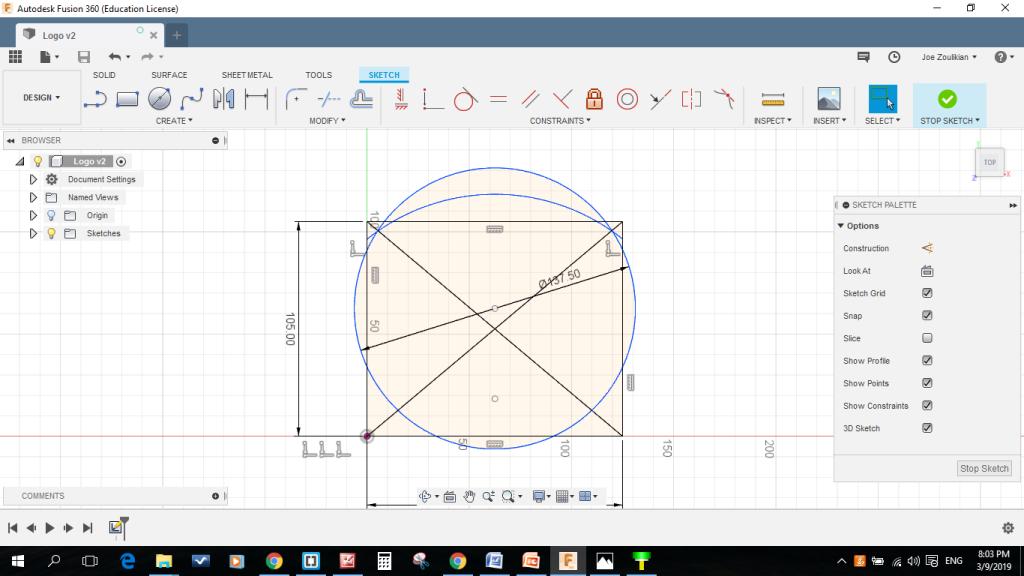
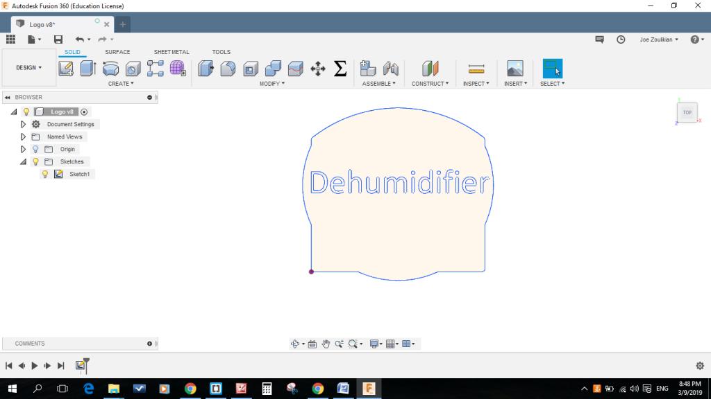
I started designing my logo to be cut on the vinyl cutter having in purpose of using it later on as a logo for my final project. I started by drawing a rectangle of 125 x 105 mm, then two circles having 137.5 and 200 mm as diameter. I trimmed the edges and fillet the corners with 4 mm diameter.
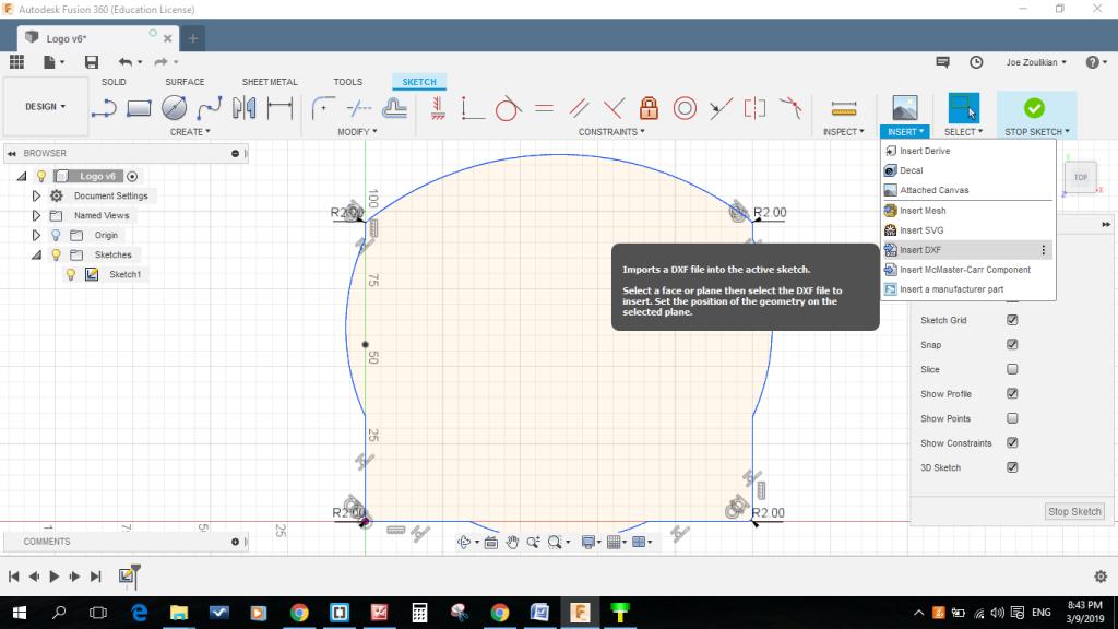
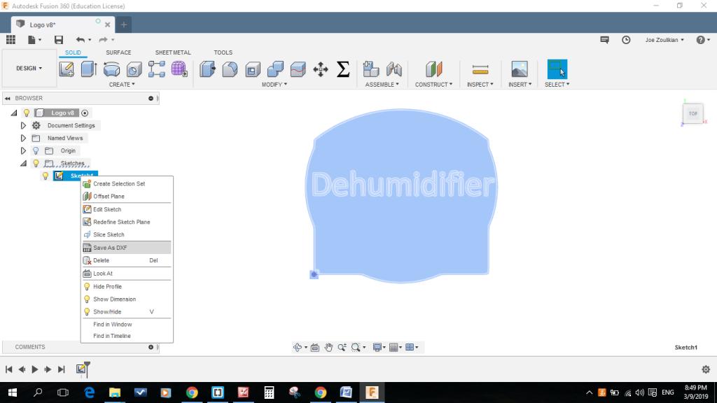
After that I used the insert .dxf function to insert the text file "Dehumidifier" and locate it. At the end I saved the file as .dxf in preparation to cut it on the vinyl cutter by using the CorelDraw software.
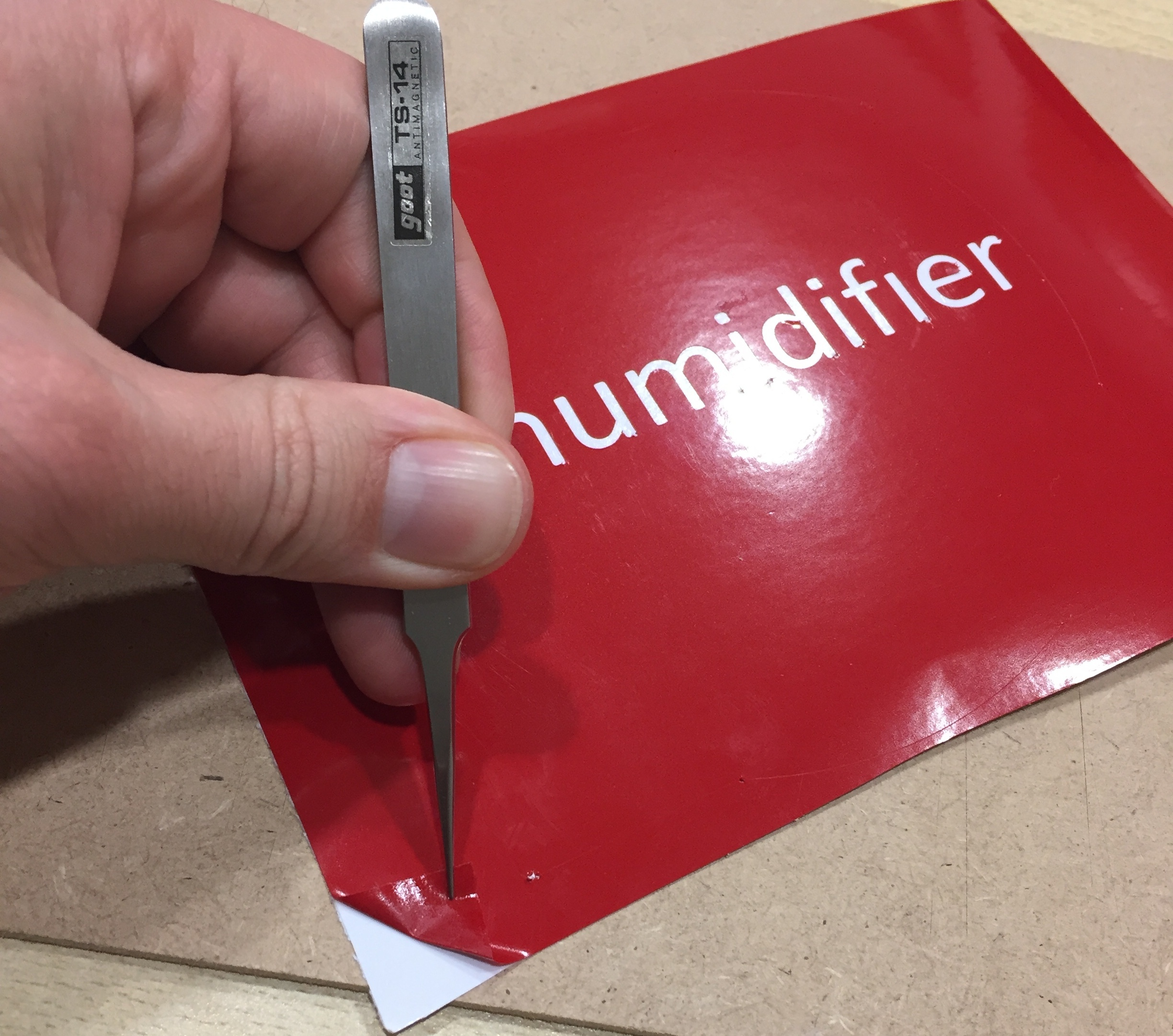
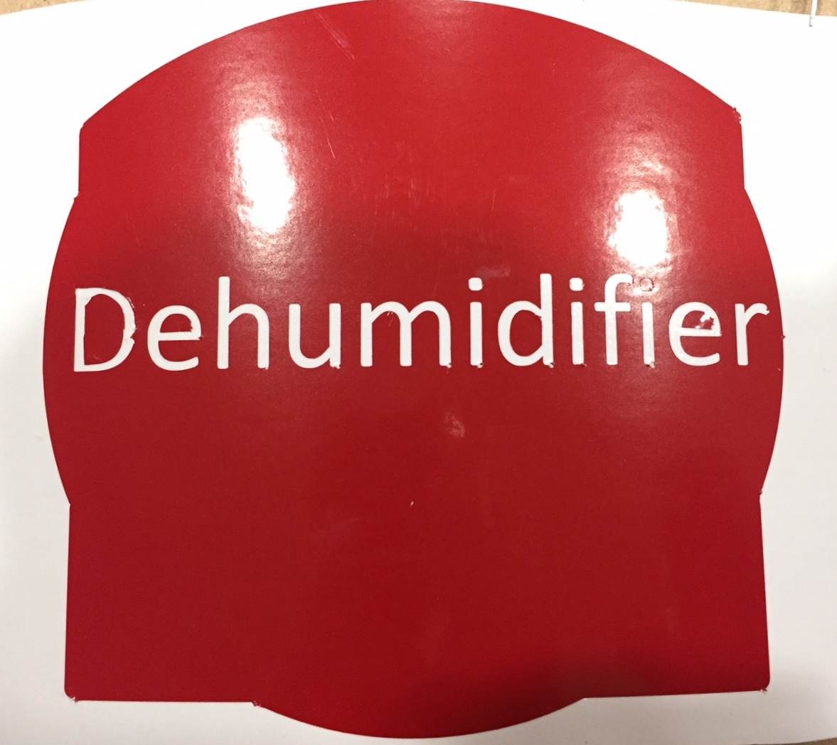
After cutting my logo on the vinyl cutter I gently removed the unnecessary materials.
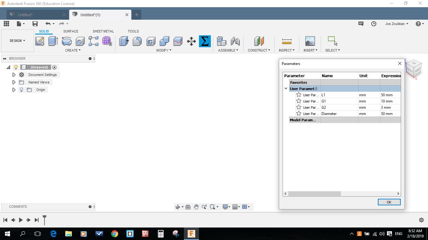
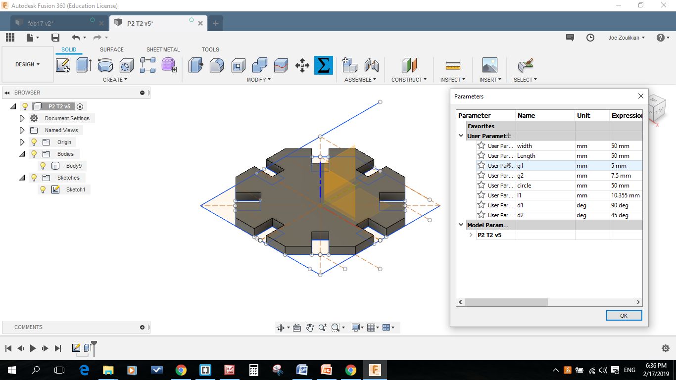
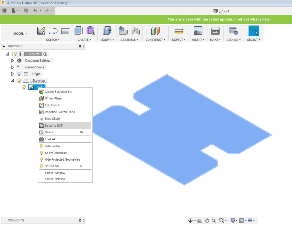
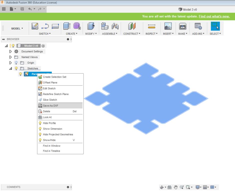
I draw the parametric design using the Autodesk FUSION 360 taking into consideration the laser cutter kerf.
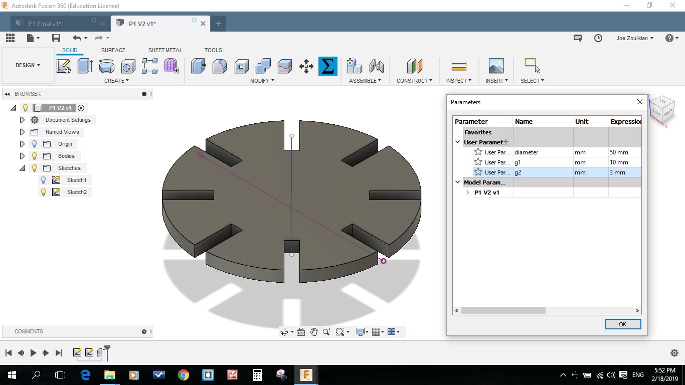
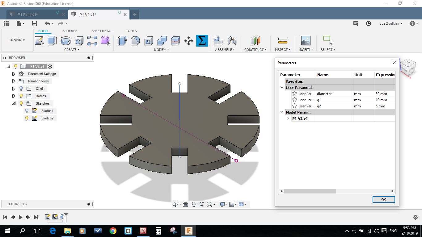
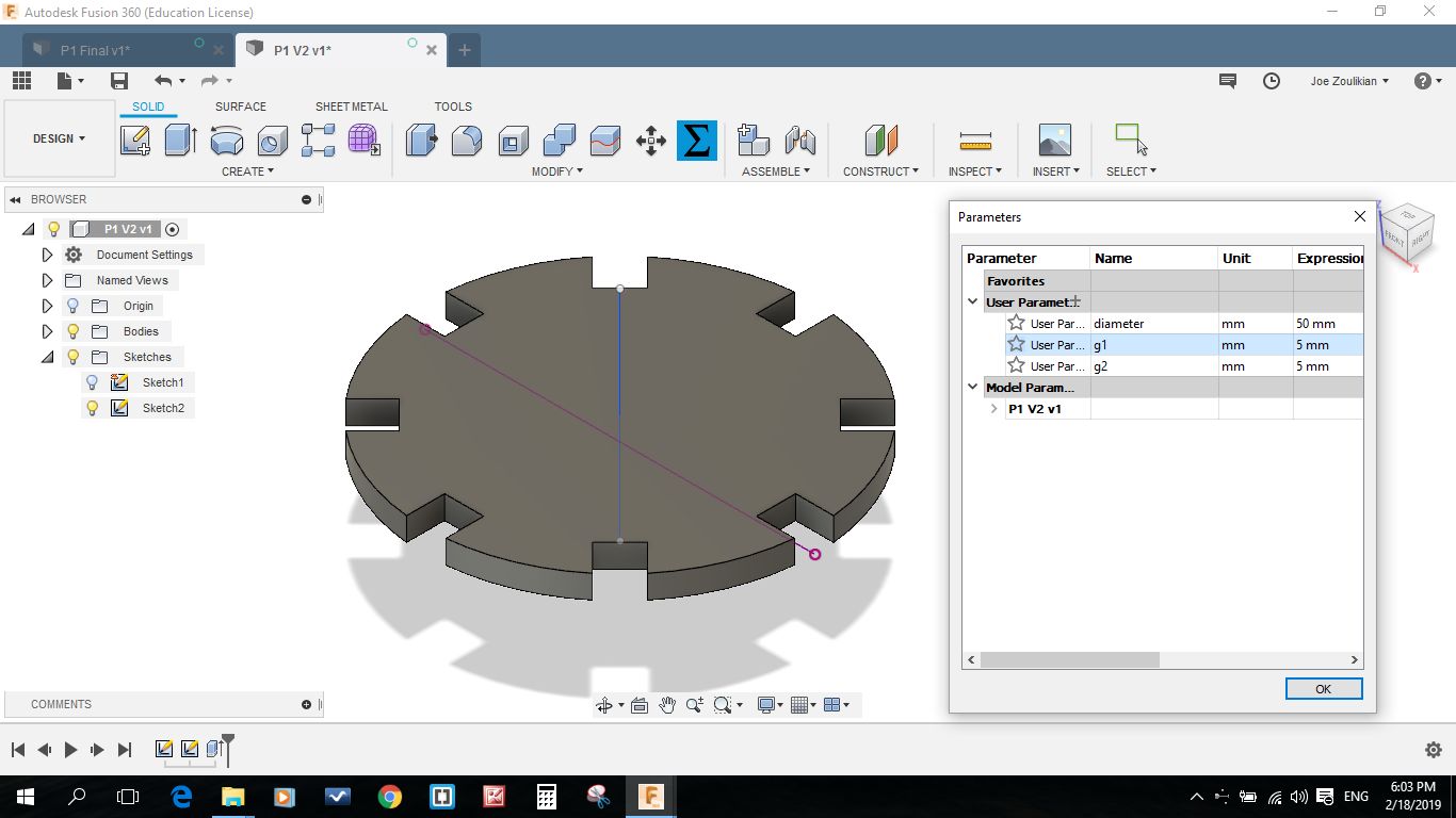
Since the available material in the market is 3.17mm not 3mm. So the additional removed kurf (0.09mm) mentioned above will totally fit with the available material. In the below test i tried different width senarios.
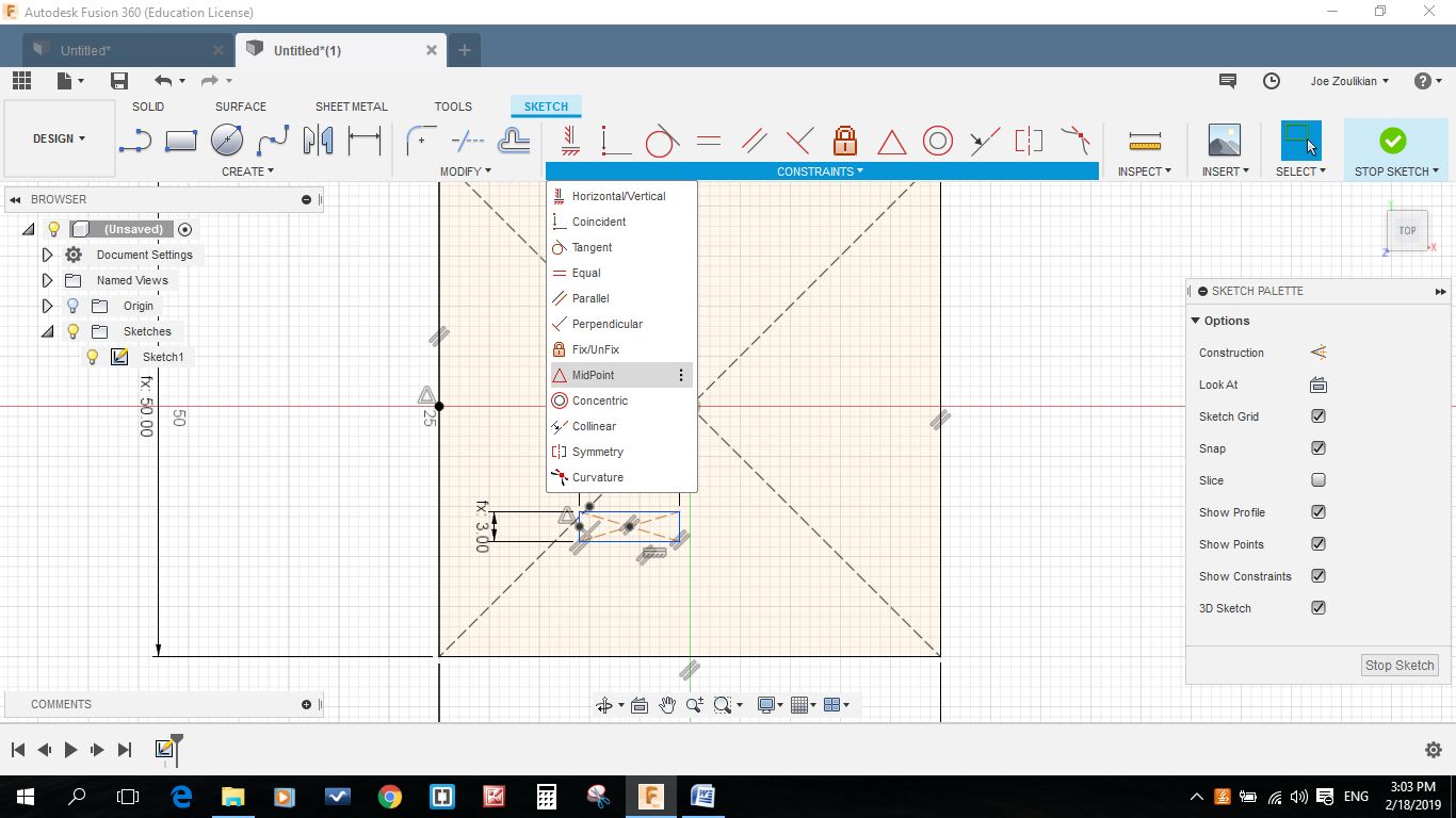
I started to draw a rectangle and enter L1 as distance, then a second rectangle with g1(10mm) and g2(3)mm. Then I created a center-point by using create point function and mid-point on one the side of the rectangle and the 50 x 50 mm square.
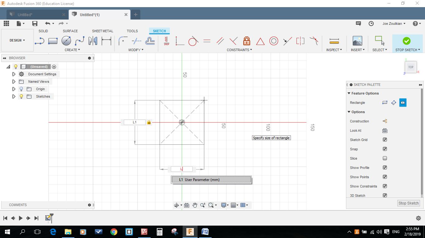
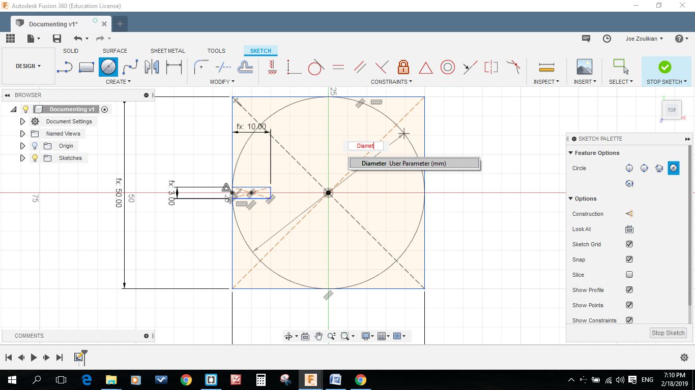
Then I used the Midpoint of the Constraints to relocate the rectangle to the left side wall of my square. After that I draw a 50mm circle using sketch shortcut and "Center Diameter Circle C" and by hitting Diameter (to use the parameters value).
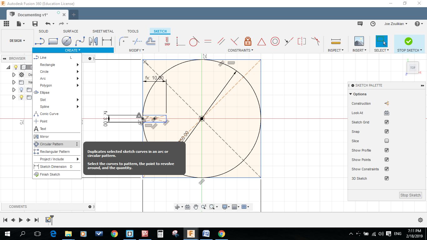
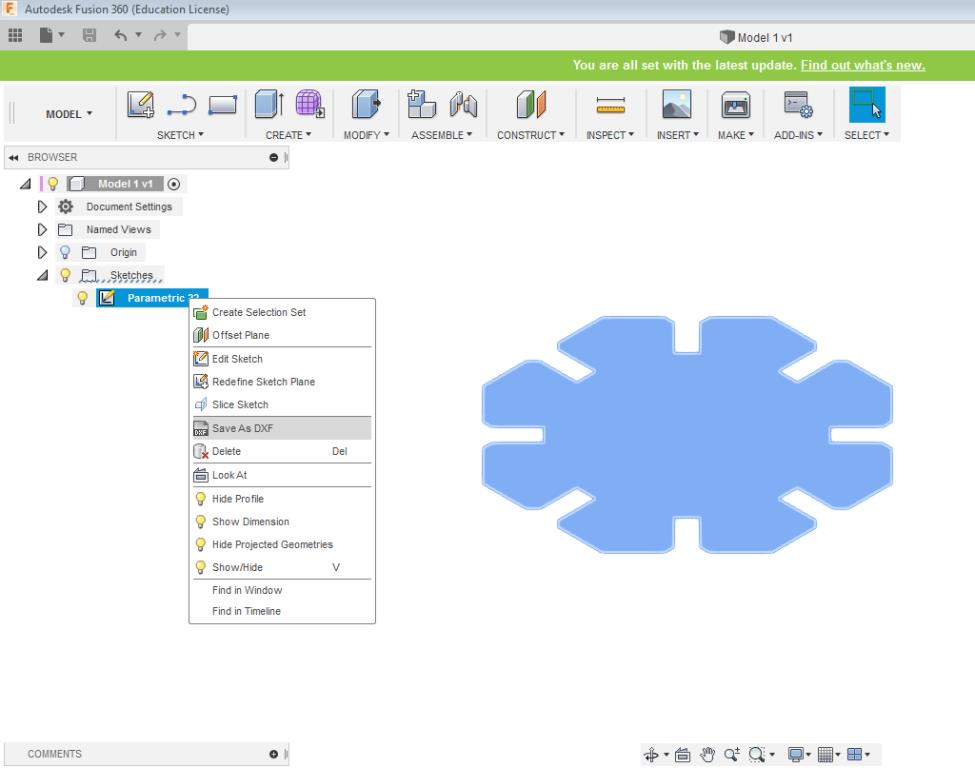
Then I used the circular pattern to draw the 7 remaining grooves. I selected the 3 lines of the groove then I selected the center of my circle as a reference to rotate and draw the remaining grooves. Then I stop my sketch and hit the extrude button and selected the black wireframe and defined 3mm as depth.
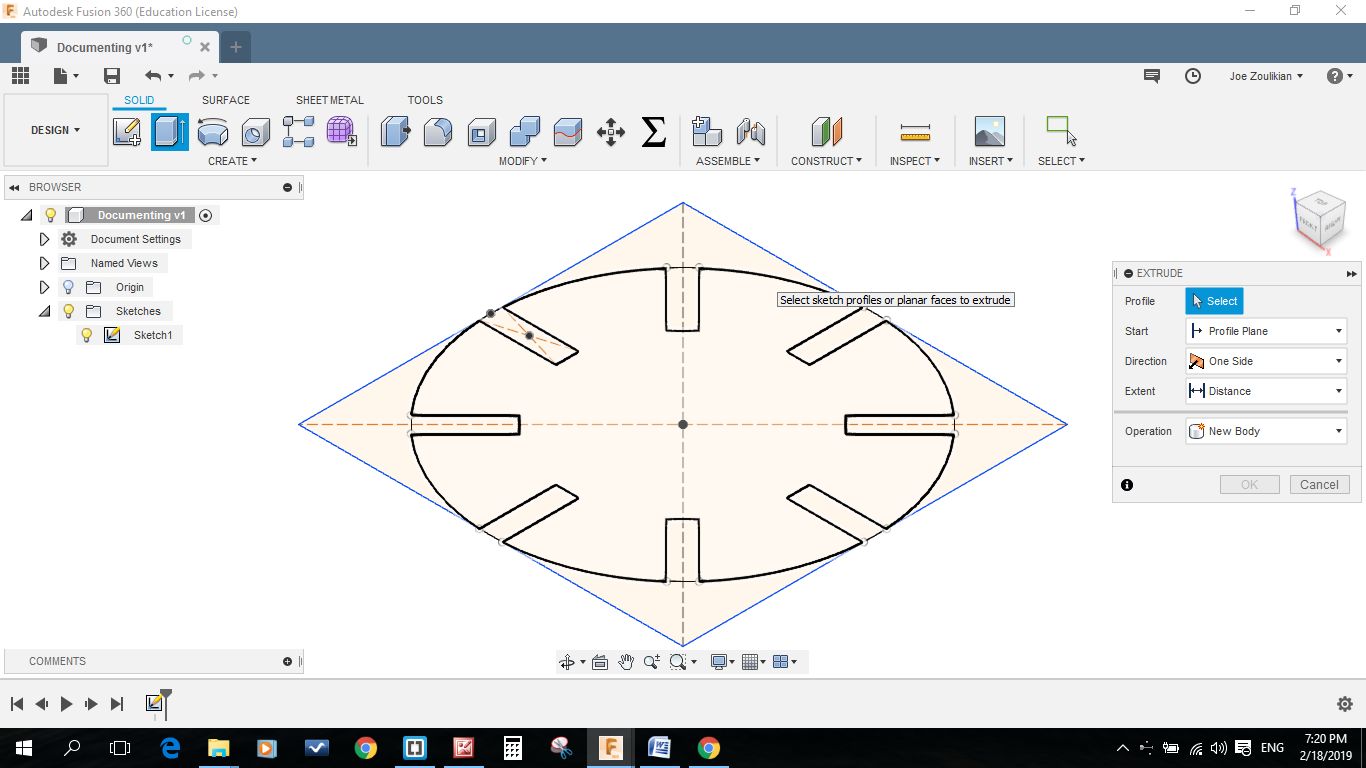
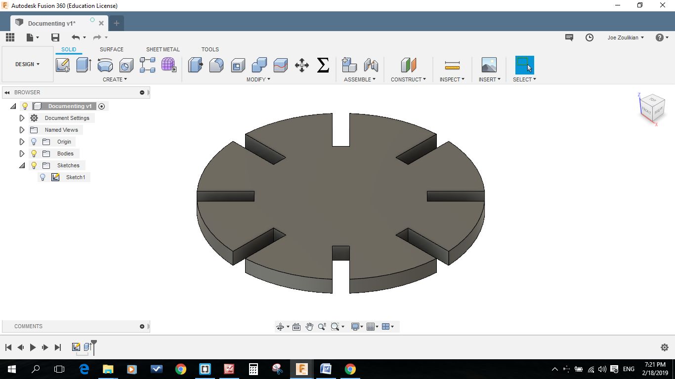
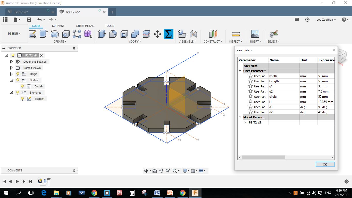
After finalizing I enjoyed the parametric function by changing the groove depth and width as you can see in the below pictures.
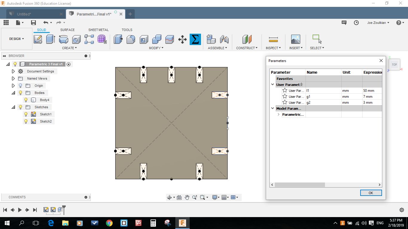
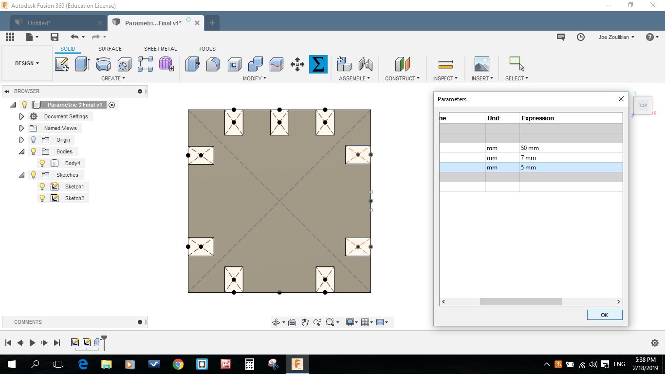
I continued the drawing of my two remaining models: hexagon and the square one. I enjoyed the parametric function by changing the groove depth and width as you can see in the below pictures.
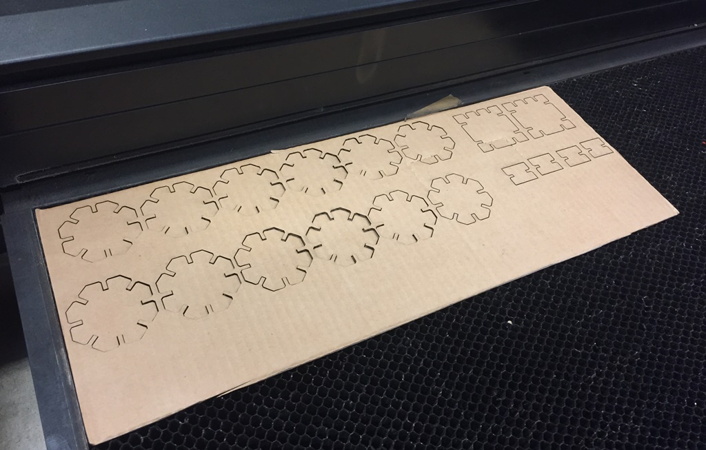
Since the press fit process can be better understood with the cardboard, I will redo my model using cardboard. In order to make the assembly process easier, I added some chamfers to the slots.
Logo Design in DXF format
Logo Design in Fusion 360
Parametric Design 1 in DXF format
Parametric Design 2 in DXF Format
Parametric Design 3 in DXF Format
Parametric Design 1 in Fusion 360
Parametric Design 2 in Fusion 360
Parametric Design 3 in Fusion 360
Link in DXF format
Cardboard Design 2 in DXF format
Cardboard Design 3 in DXF format

This work is licensed under a Creative Commons Attribution 4.0 International License.