During the sixteen session dated May 8 2019, the objective is to write an application that interfaces with an input &/or output device made by me.
The group assignment is to compare as many tool options as possible
Individual Assignment:
Processing is a flexible software sketchbook and a language for learning how to code within the context of the visual arts. Since 2001, Processing has promoted software literacy within the visual arts and visual literacy within technology.
Tens of thousands of students, artists, designers, researchers, and hobbyists uses Processing for learning and prototyping.
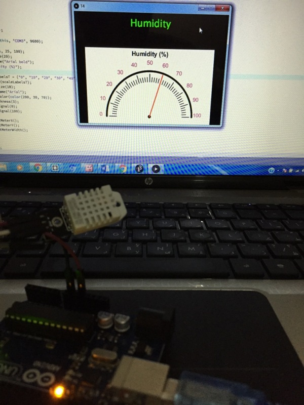
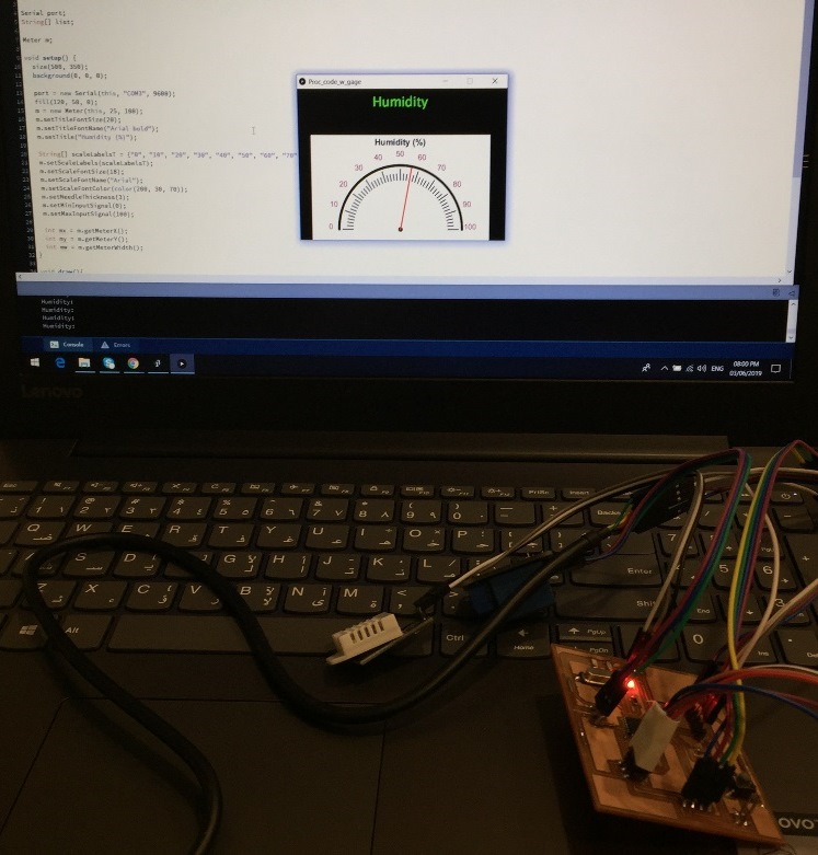
To start I practiced the basic communication between Arduino and Processing. At the end, I will visualize the ambient "Humidity" level gathered by the Humidity Sensor DH-22 on the software's window.
Basic Communication between Arduino and Processing:
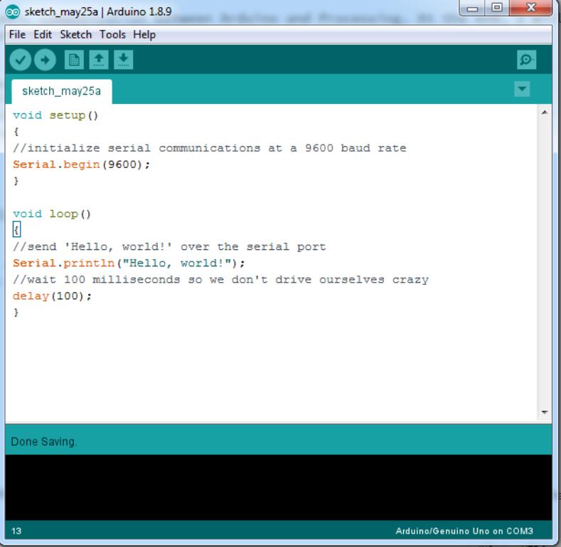
Send data from Arduino to Processing over the serial port,
I initialized the serial communications at a 9600 baud rate.
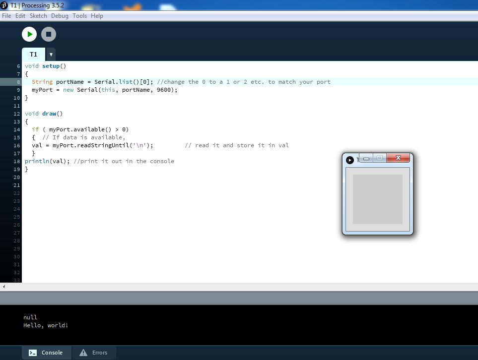
Then I will send a message 'Hello, world!' over the serial port.
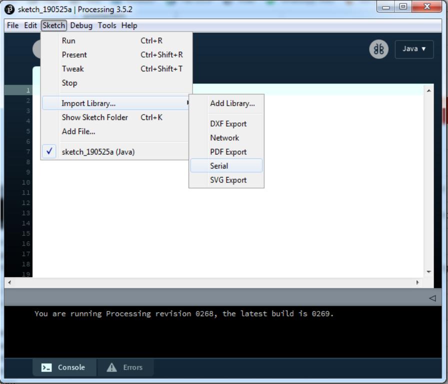
Receive data from Arduino in Processing,
Processing comes with a Serial library to open it I go to Sketch, then Import Library, then Serial, as shown below:
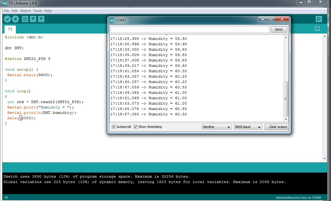
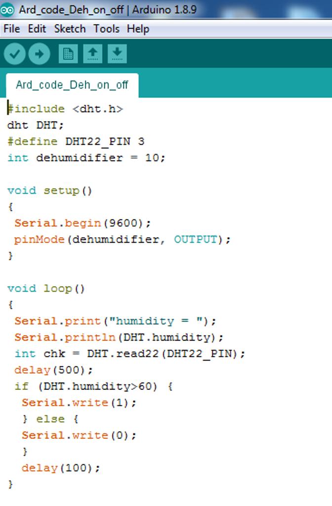
Reading the value from the Humidity Sensor "DHT-22",
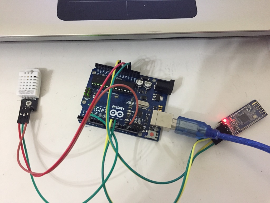
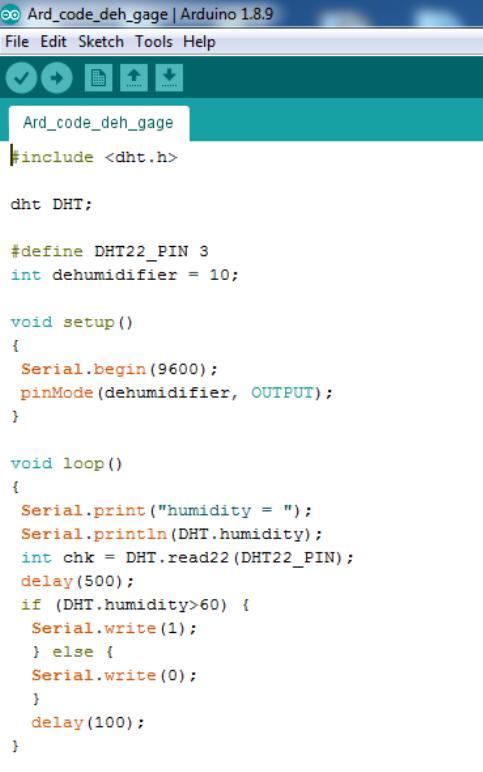
I connected the DHT22 to Digital pin 3 of Arduino as well as VCC and Gnd. I wrote and sent the code in Arduino, after that I checked the values through the serial monitor.
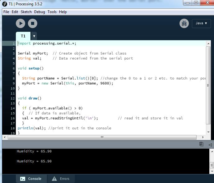
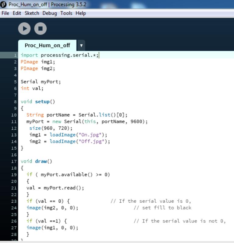
Now it is time to write the code on Processing and read the value.
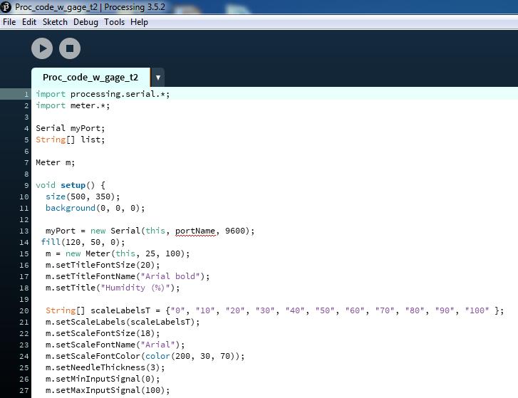
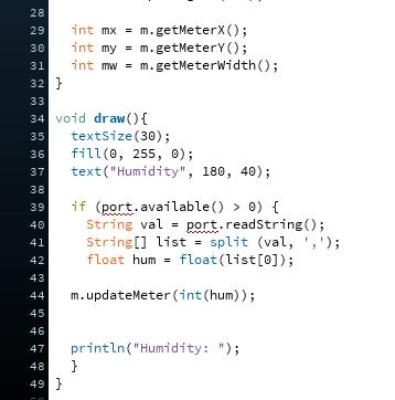
Visualizing the values on Processing,
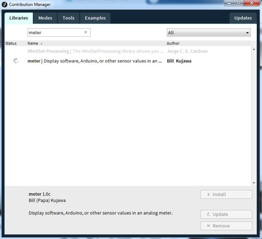
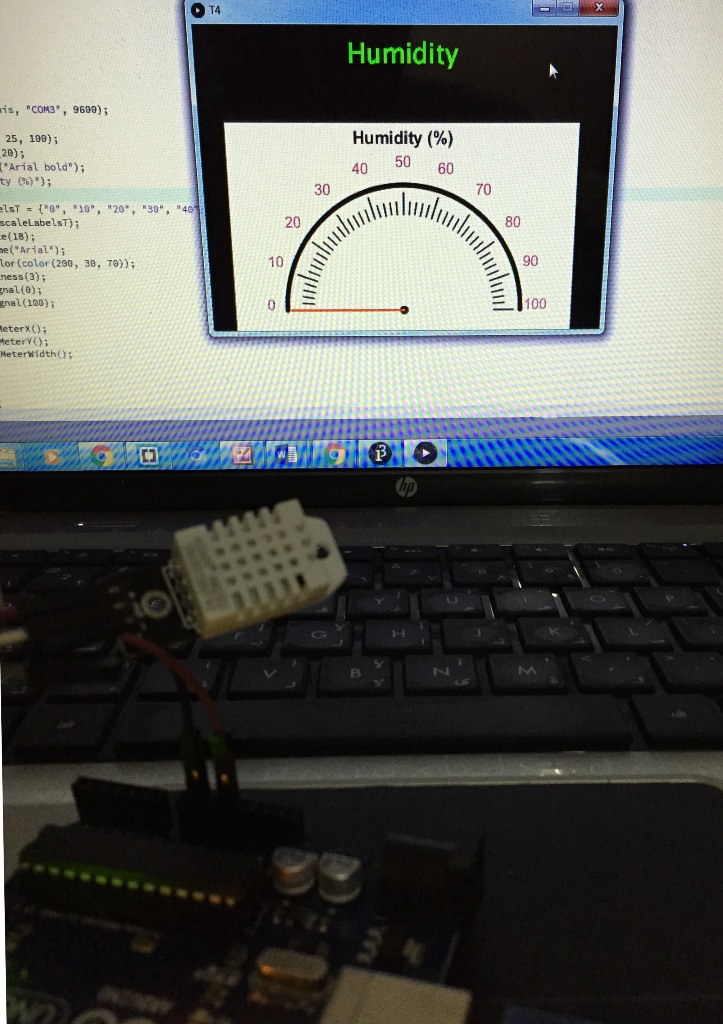
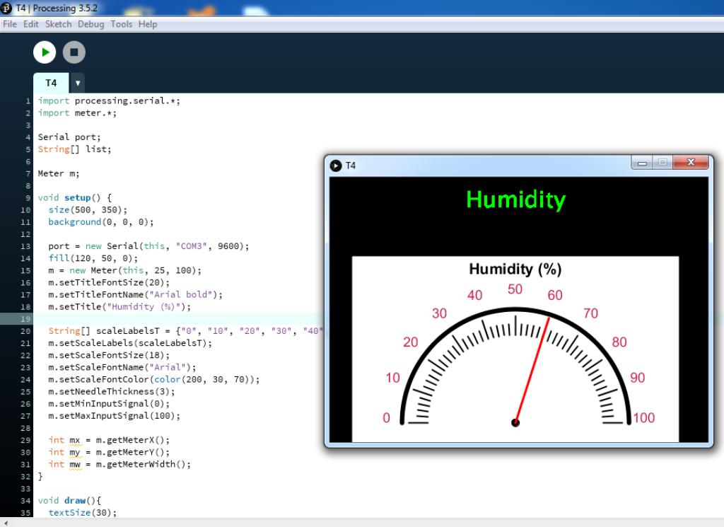
I started by making an Analog meter by installing the meter library.
Then I wrote the code having in reference this youtube video:
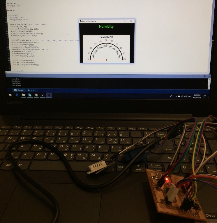
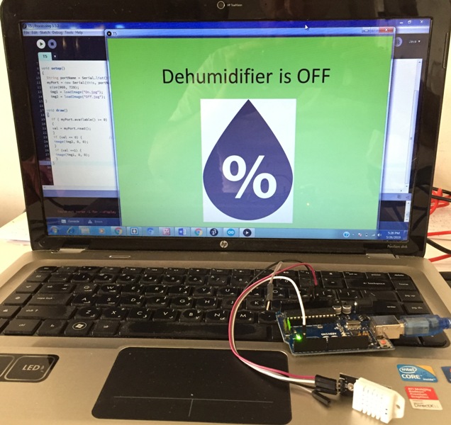
After using Arduino board, I connected my PCB and tested again the application by using the below Arduino and Processing Codes.
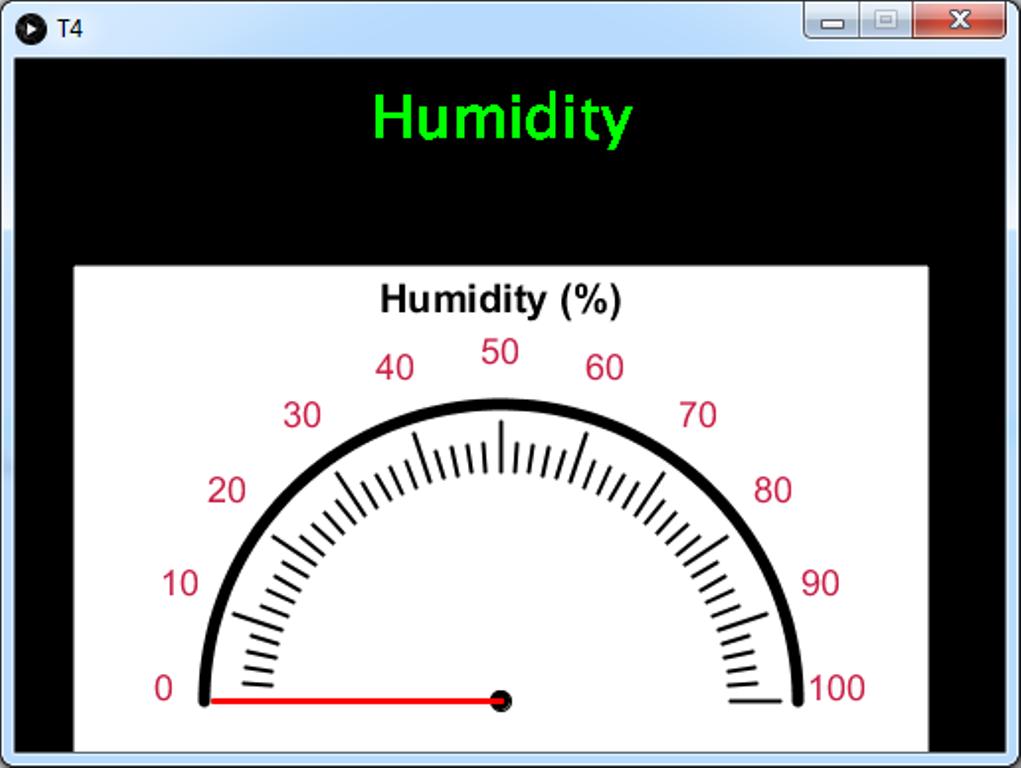
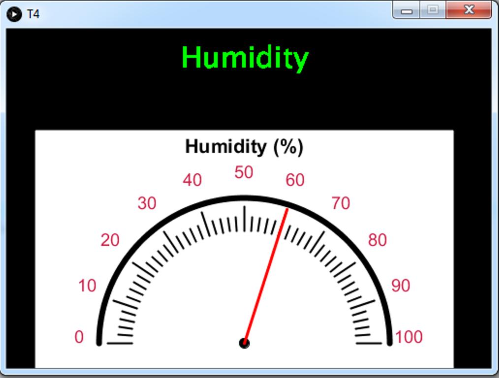
As you see in the below pictures and video the gage was initially at 0, at some point it shows the ambient humidity level around 60%. When I blow some fresh air toward the sensor as a result the Humidity reached 80%.
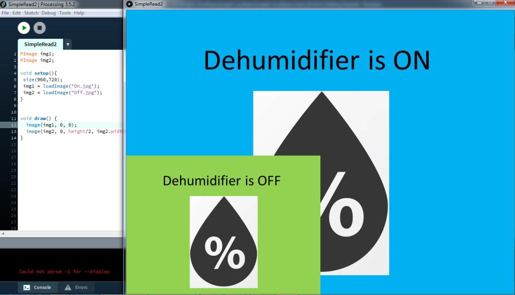
Visualizing images on Processing:
To include images, I check sketch, show sketch folder, I add a new folder named Data and I save or store my images to be used.
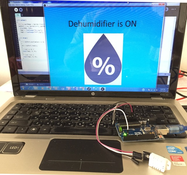
Now I will connect the DHT-22 to Arduino and set the Humidity level in the code to 60%, so that whenever the Humidity level exceeds this limit the Application will display the image confirming that the Dehumidifier is turned On.
In the below pictures and video you can see that the Dehumidifier was Off, I blow some fresh air toward the sensor as a result the Humidity exceeded the 60% and the Image was changed to Dehumidifier On.
After testing using Arduino board, I connected my PCB and tested again the application using the below Arduino and Processing codes.
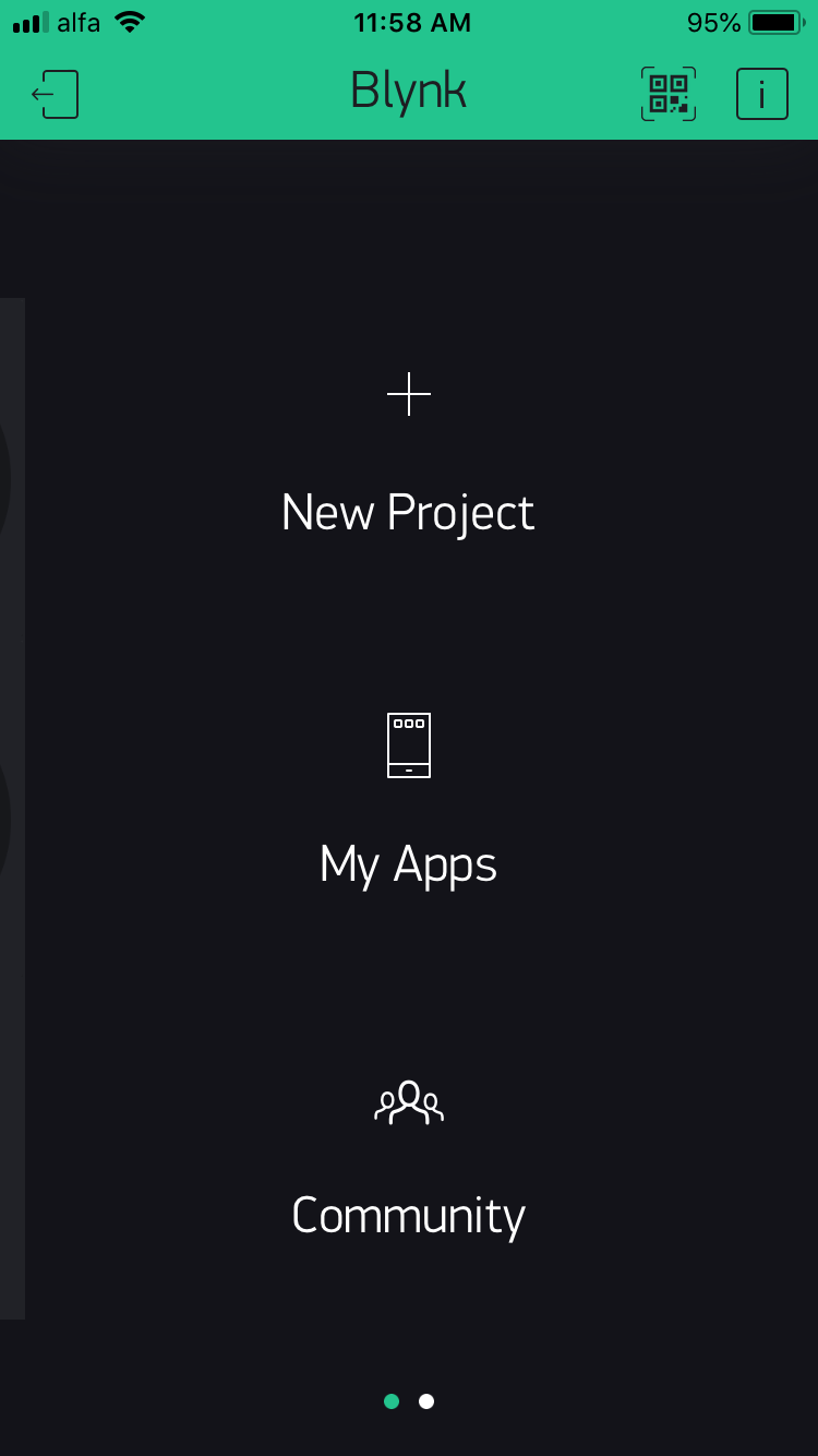
Blynk is a simple and easy to implement user interface, it facilitates the access to our project via mobile phone.
In order to use it:
I downloaded the Blynk application on my Iphone,
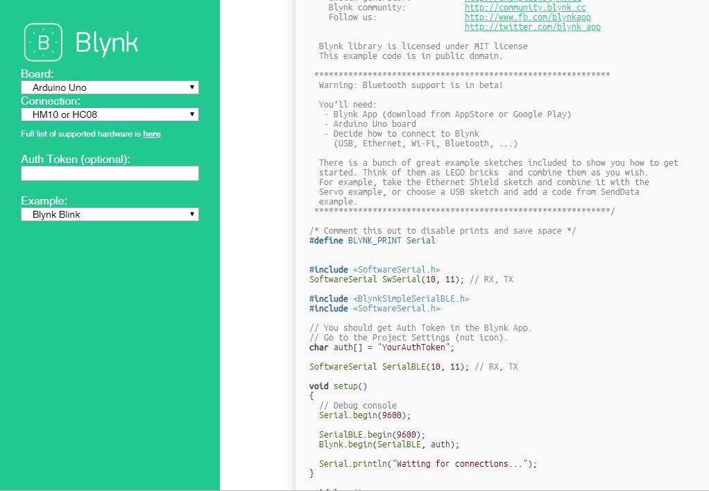
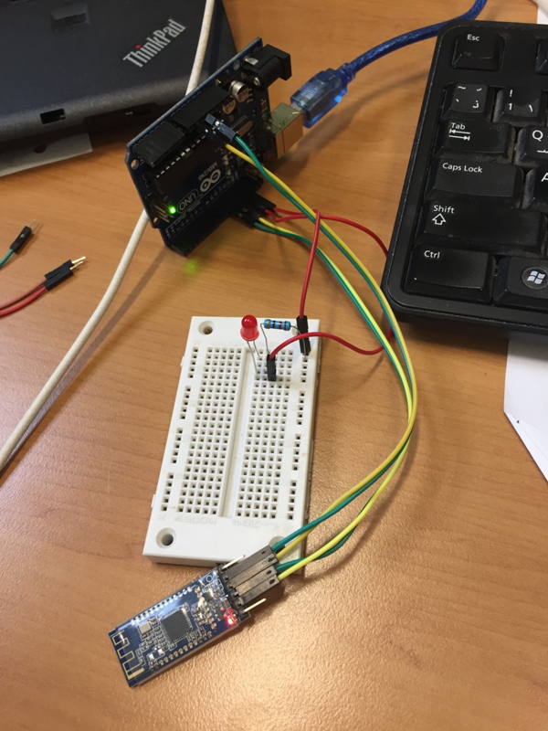
I included the Software Serial, and installed the Blynk Library in Arduino,
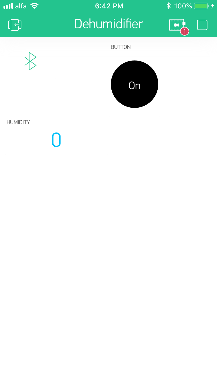
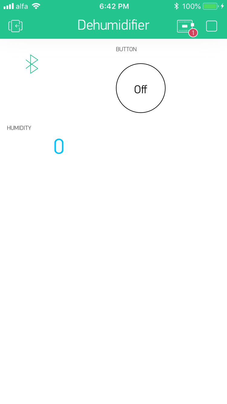
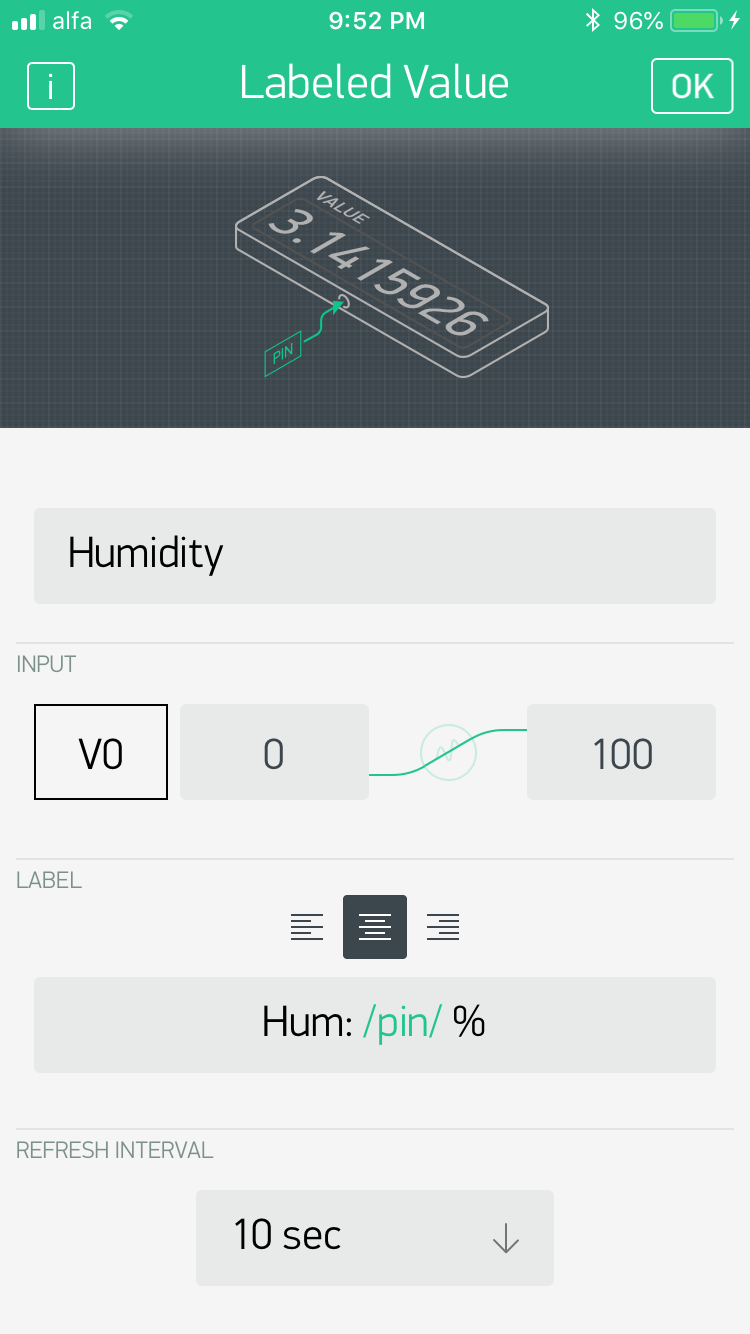
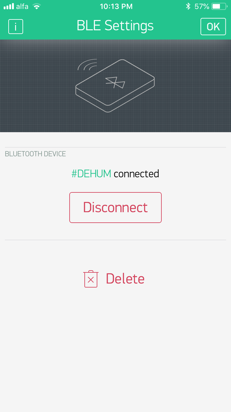
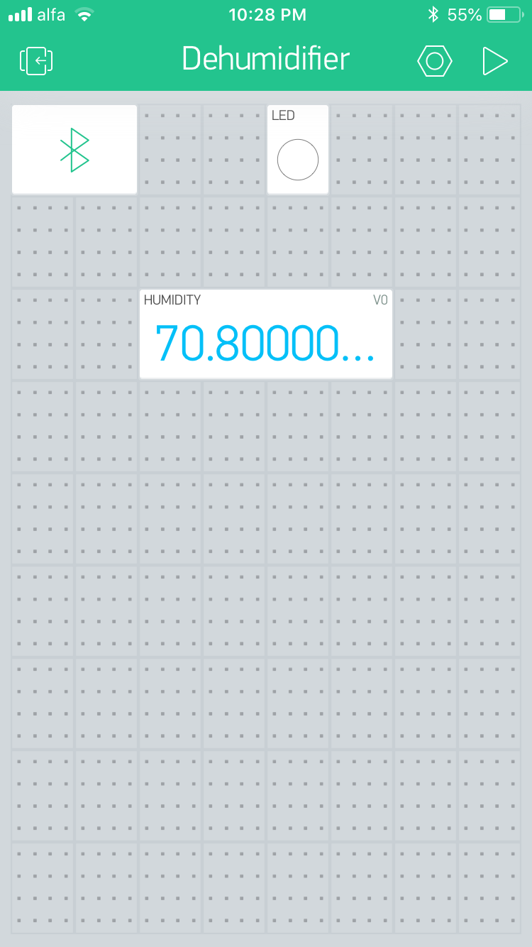
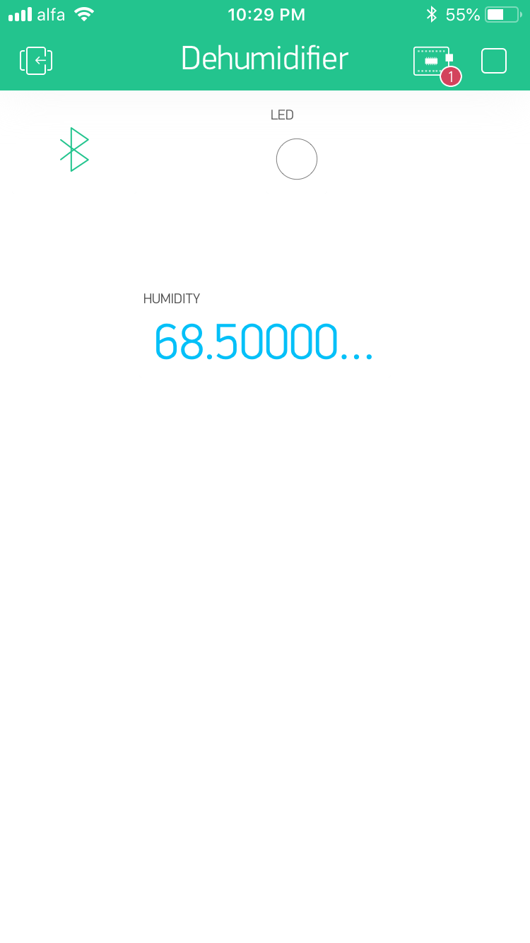
In order to connect the Dehumidifier via HM-10 to my Iphone to read the Humidity level and the status of the machine, I practiced "Blynk" using the Sketch Code Builder to turn a Led On and Off.
I opened the app and created a new account, I entered my email and a password.
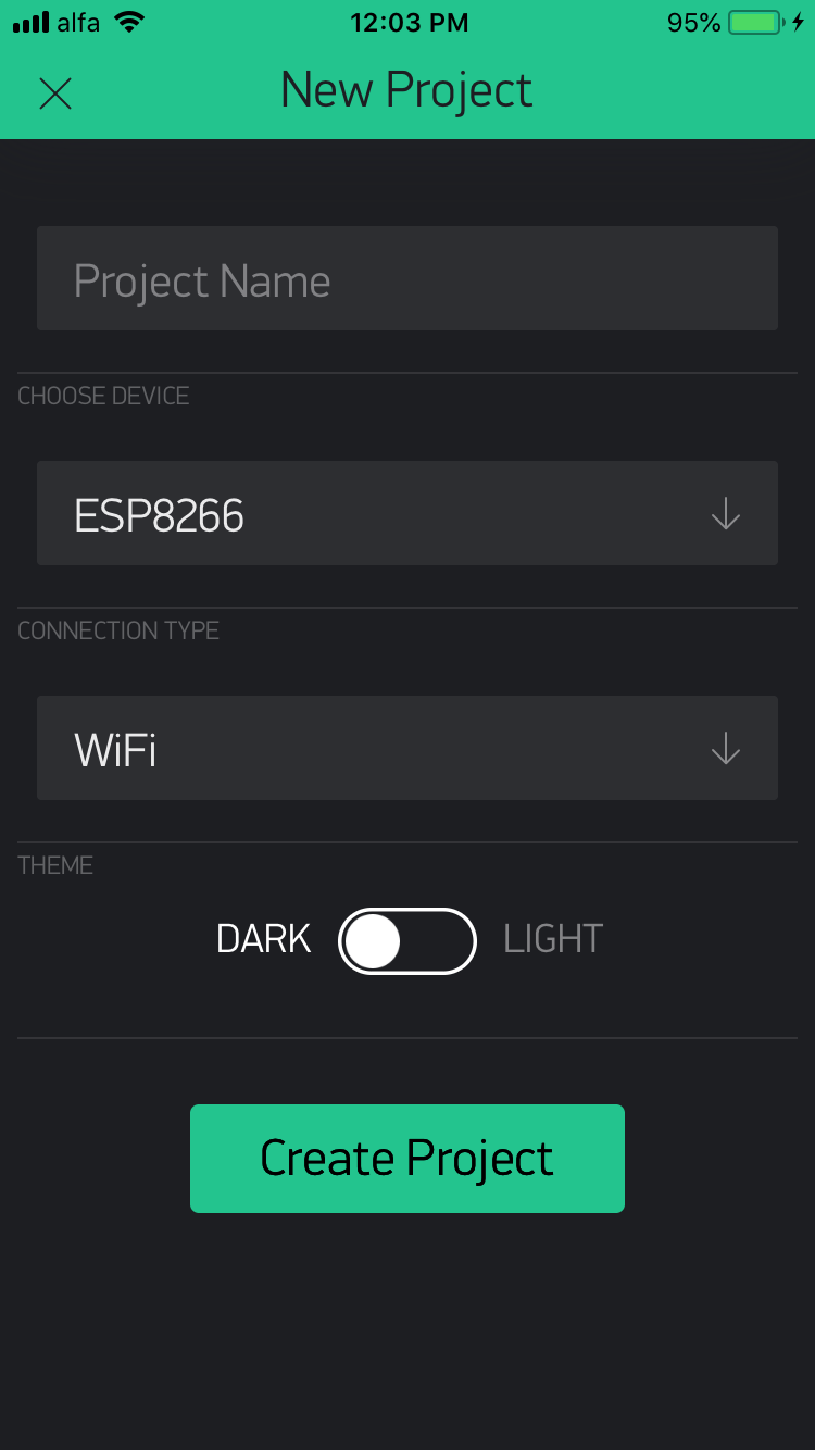
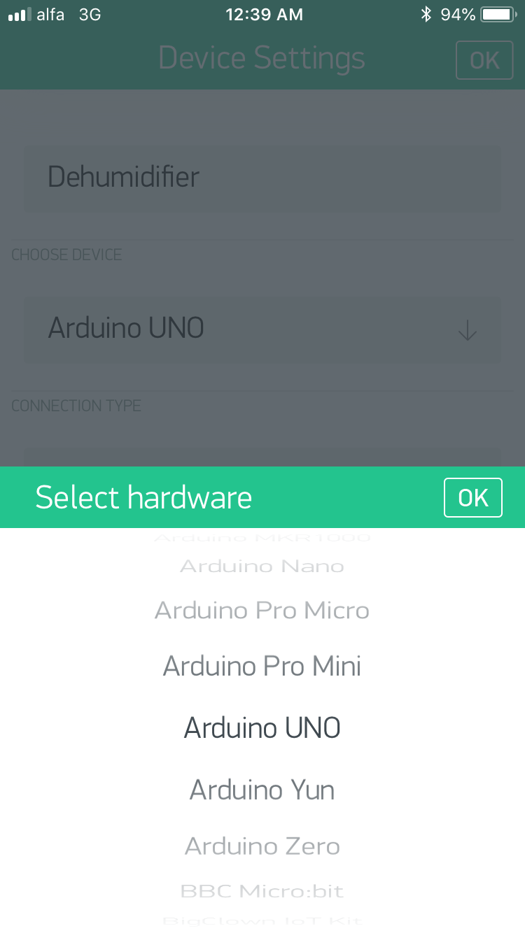
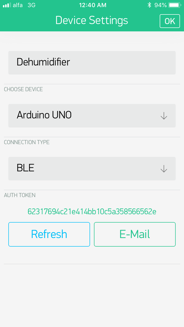
I started a new project, named it "Dehumidifier" and selected Arduino Uno as software.
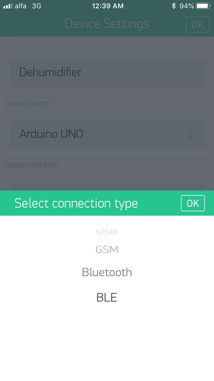
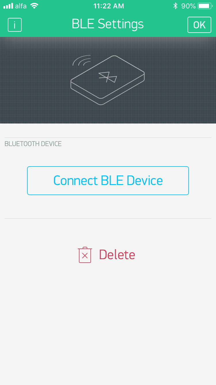
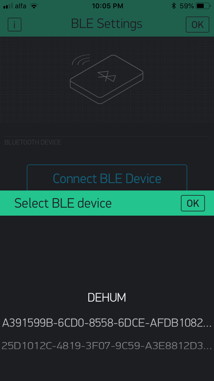
I selected "BLE" as communication type,
BLE stands for "Bluetooth Low Energy" is a form of wireless communication designed especially for short-range communication. However, BLE is meant for situations where battery life is preferred over high data transfer speeds.
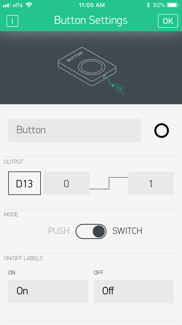
then I pressed create, and inserted a simple button and set it to D13 and a inserted a BLE connection Icon to be able to connect to Arduino.
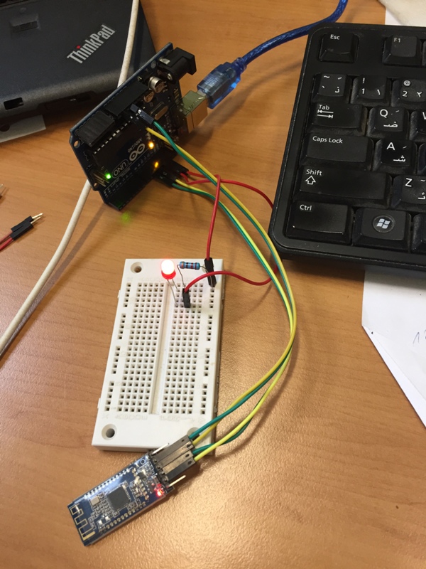
The wiring between the HM-10 and Arduino: Tx to Rx and Rx to Tx.
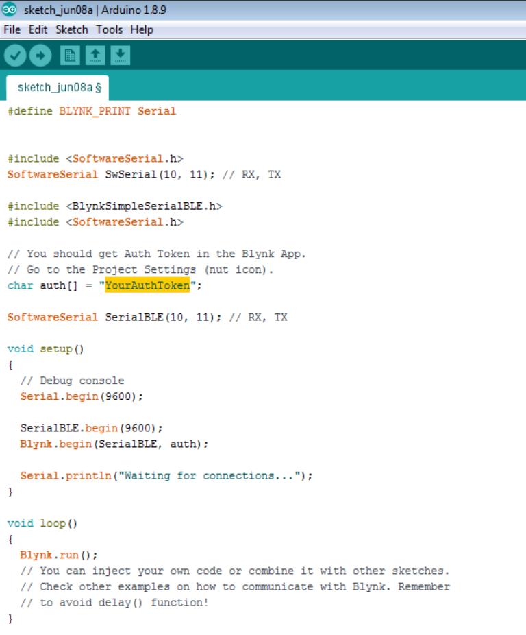
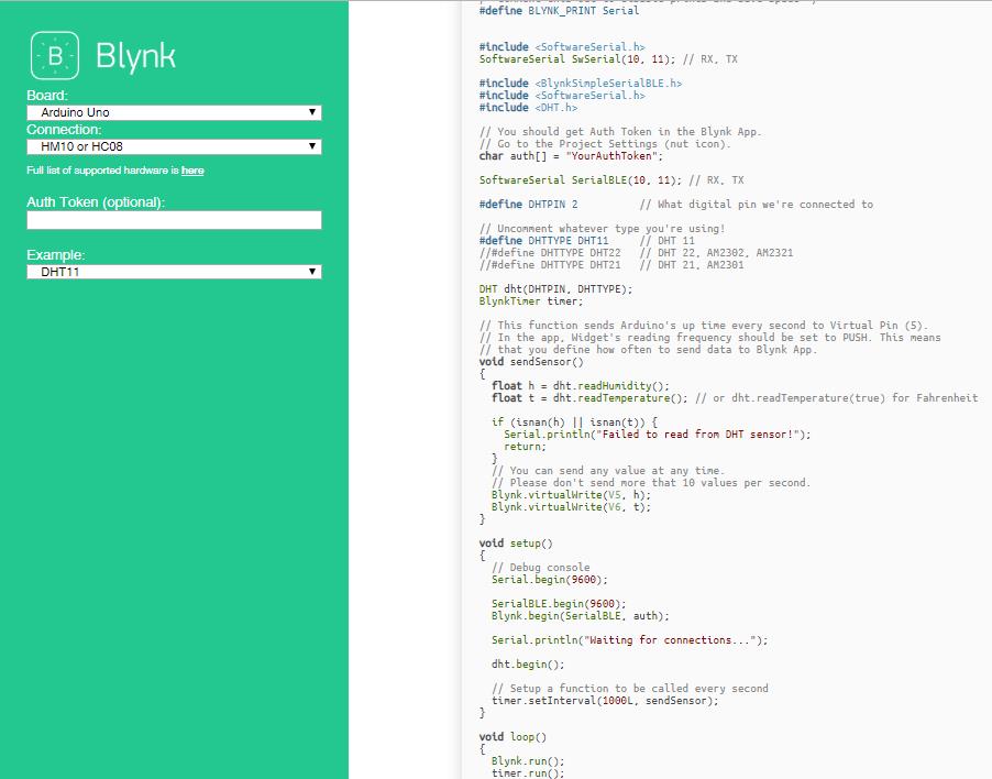
To get it online and connect it to Blynk Cloud, I need a device Authentication Token.
To receive it, I entered my email and the app had generated the Authentication Token and sent to my email.
Every time we prepare a new project a new Autotication code will be generated in order to connect the Application to our Arduino via the different connections type.
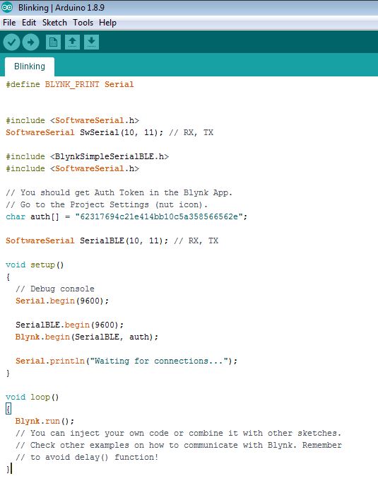
I entered the "Authentication Token" code received through email and place it in "YourAuthToken" highlighted in yellow.
Since my App will receive data from the PCB, like the Humidity level and the Dehumidifier status (On/Off), I used as a reference the below example "DHT 11" from the official
Blynk website.
After commending a LED to turn ON/OFF from my mobile during the previous application, I will receive the Humidity level from my PCB through DHT-22 in the following application.
.jpg)
.jpg)