
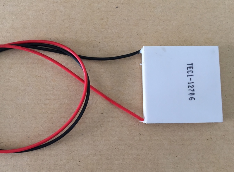
Data Sheet of TEC1-12706
The Concept:
A Dehumidifier is an electrical appliance which reduces and maintains the level of humidity in the air by extracting water from the air. I will choose the type of "Thermoelectric dehumidifiers" for my project that uses a "Peltier" heat pump to cool a surface and condense water vapor from the air. The design is simpler and has the benefit of being quieter compared to a dehumidifier with a mechanical compressor.
Thermoelectric cooling uses the Peltier effect to create a heat flux between the junction of two different types of materials. A Peltier cooler, heater, or thermoelectric heat pump is a solid-state active heat pump which transfers heat from one side of the device to the other, with consumption of electrical energy, depending on the direction of the current. Such an instrument is also called a Peltier device, Peltier heat pump, solid state refrigerator, or thermoelectric cooler (TEC).
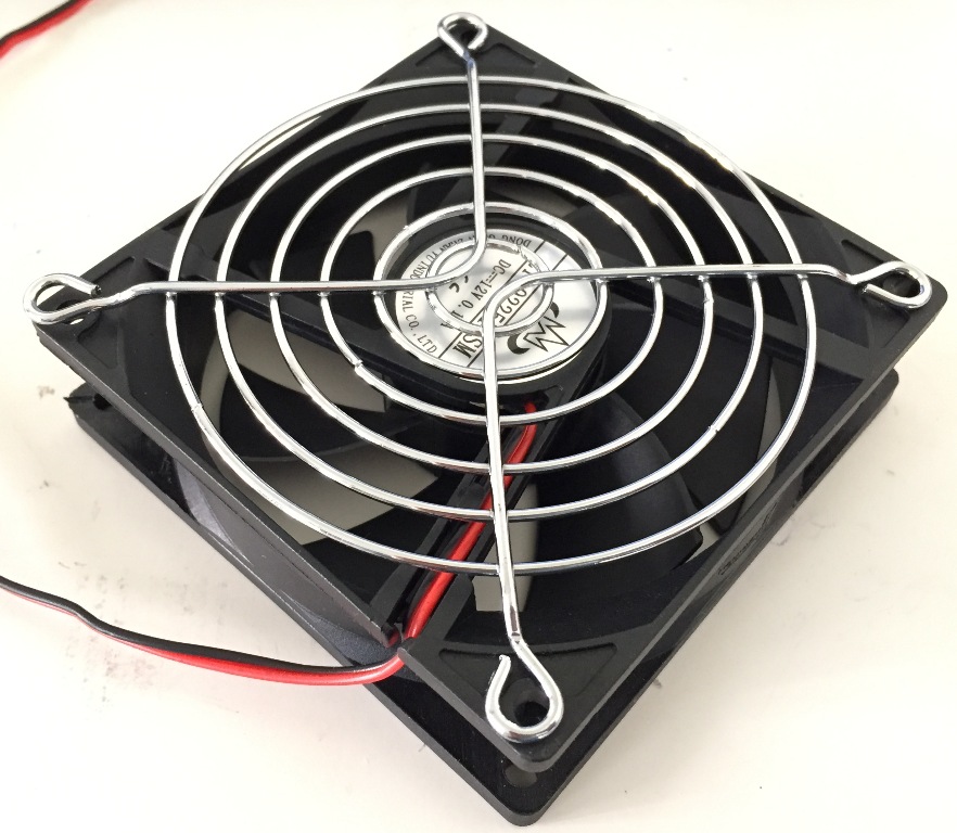
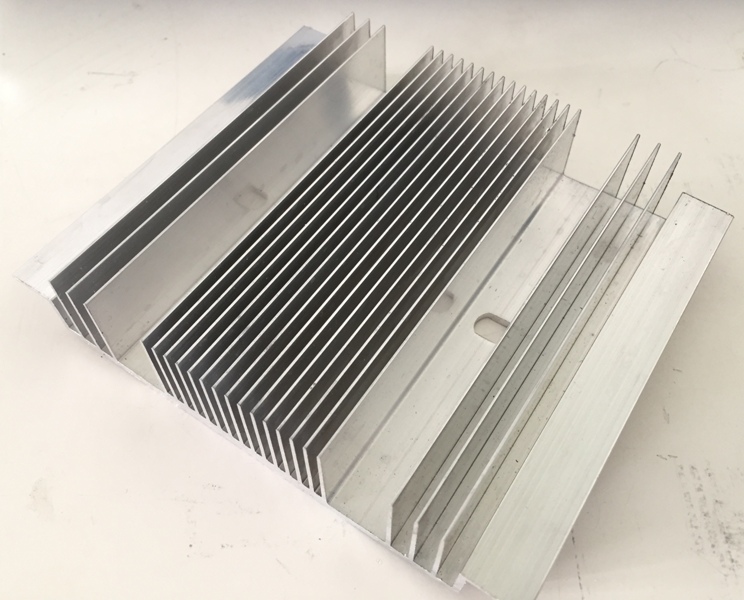
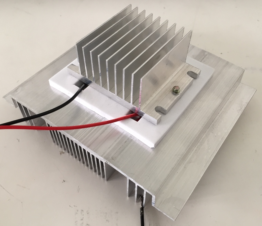
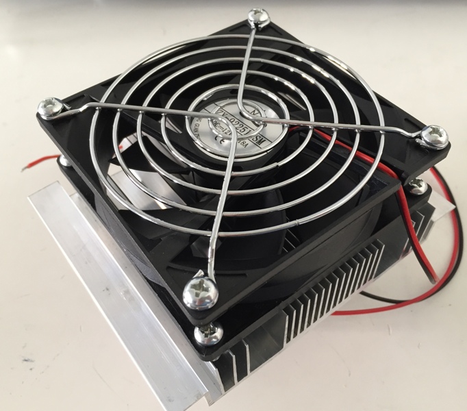
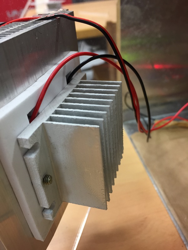
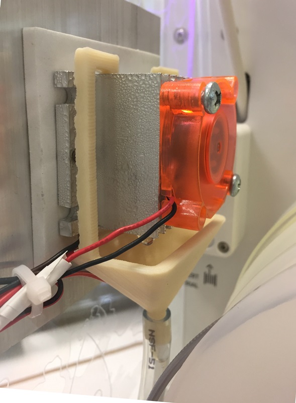
The Peltier module is sandwiched between the two heat sinks. One side of the Peltier module gets cold and the other side gets hot when electricity is run through it. The cold side of the module is in direct contact with one heat sink. The hot side of the module is in direct contact with the other heat sink. The cold side heat sink is on the side of the dehumidifier where warm humid air enters the front of the dehumidifier. The hot side heat sink is on the back side of the dehumidifier. Behind the hot side heat sink is the small brushless fan that pulls air through the whole assembly.
So we have, in order from the front of the dehumidifier where air enters to the back of the dehumidifier where air exhausts through the top:
The Process
Warm humid air enters the dehumidifier through the front grille. It is being pulled into the dehumidifier by the fan at the back of the dehumidifier. This warm humid air first comes into contact with the front of the cold side heat sink. Here is where dehumidification occurs. Just like warm air condenses onto the cold evaporator coils of a compressor based dehumidifier, the warm air that enters the thermo-electric dehumidifier condenses onto its cold side heat sink. The cold side heat sink has a smooth finish with an angled finned design to allow for the condensate to easily drip down into the condensate collection reservoir below it.
Keep in mind that the same air is still being pulled into the back of the dehumidifier. The air essentially travels around this front cold side heat sink and the whole Peltier module/ heat sink assembly to the back of the dehumidifier. Here the air is pulled past the hot side heat sink. The air exhausts out of the dehumidifier as warmer (because of the hot side heat sink) dryer (because of the cold side heat sink) air.
Reference:dehumidifierbuyersguide
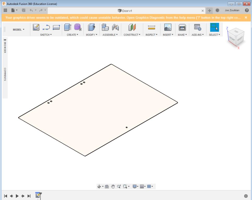
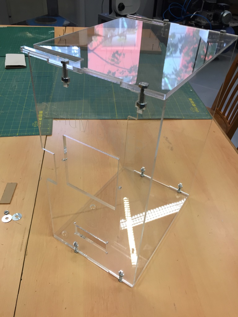
A first draft of my final project.
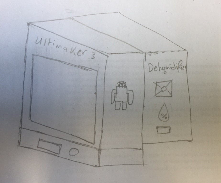
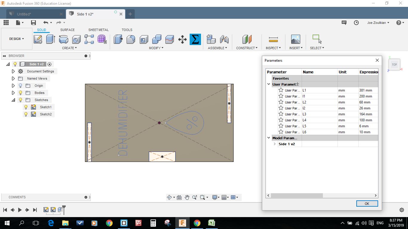
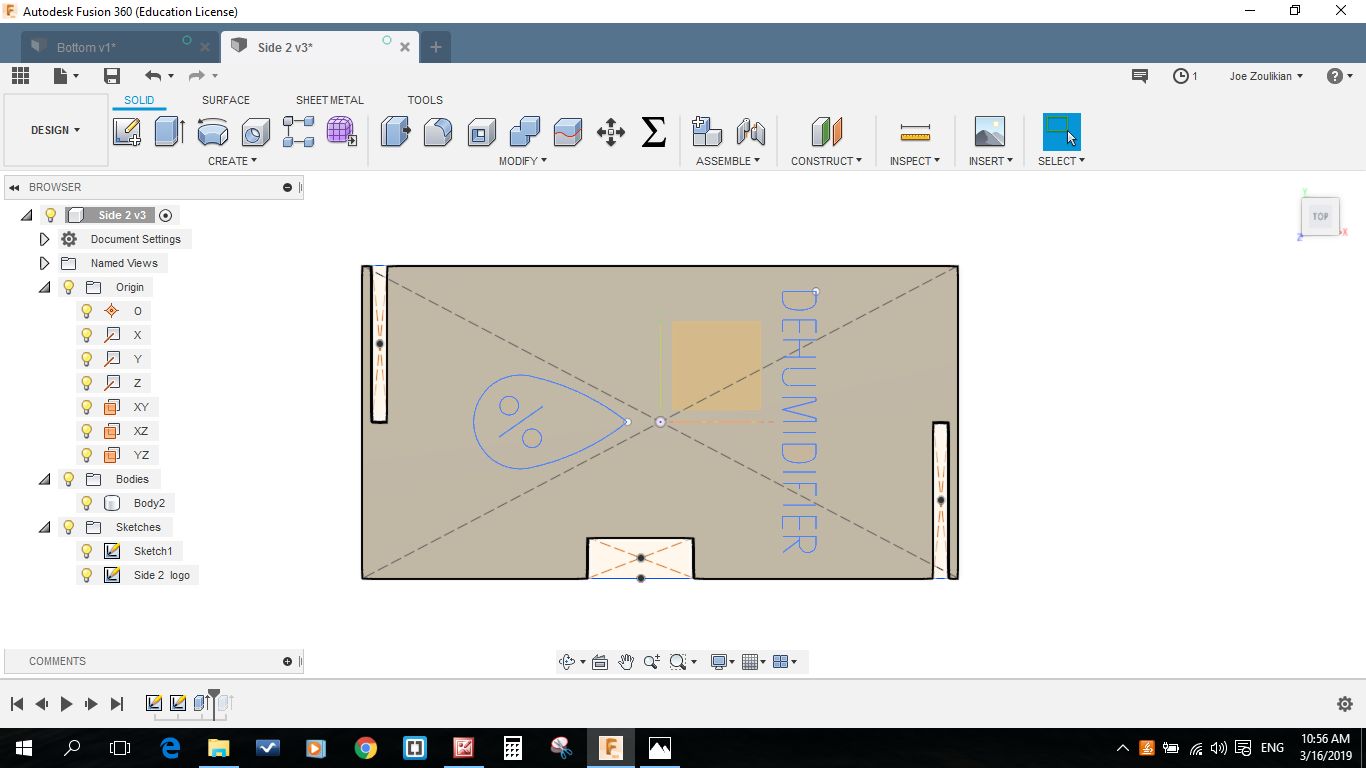
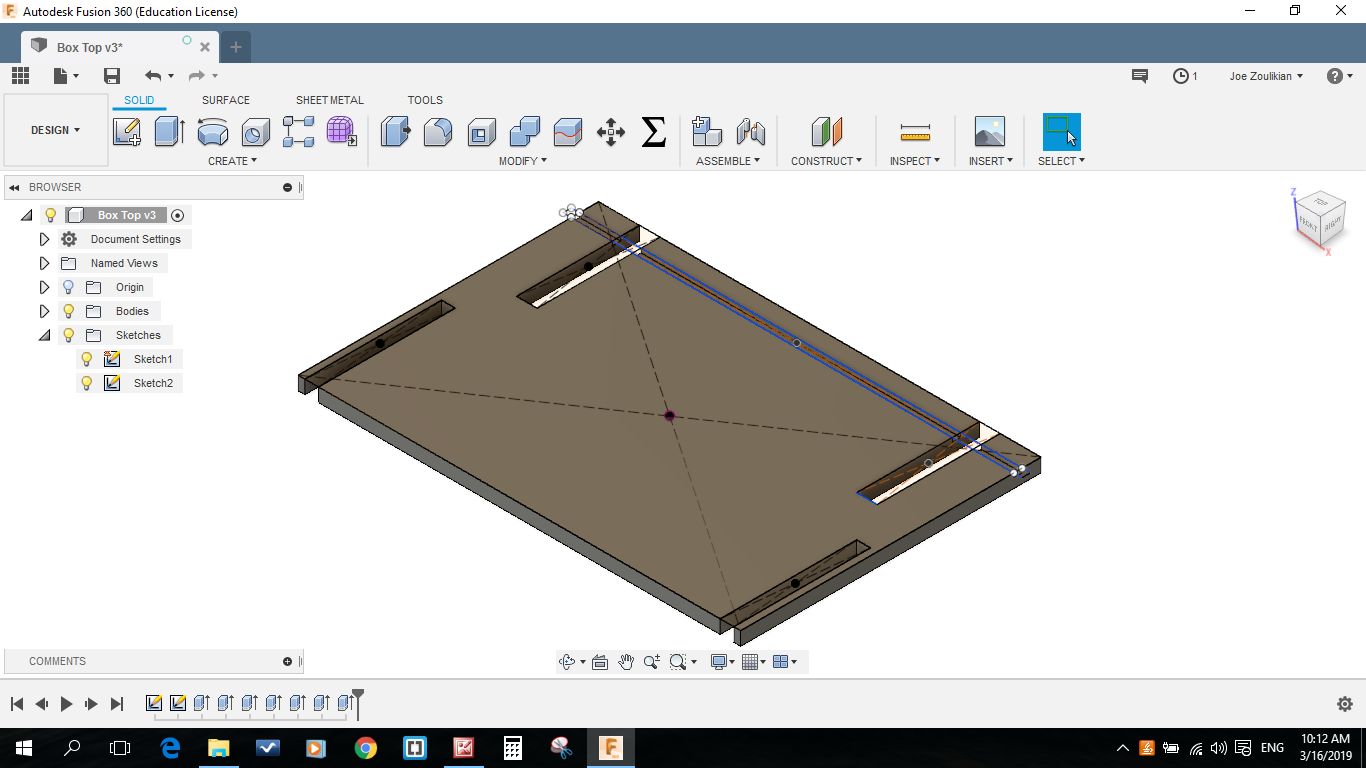
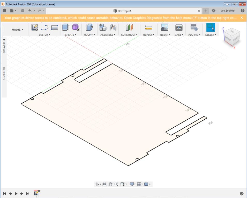
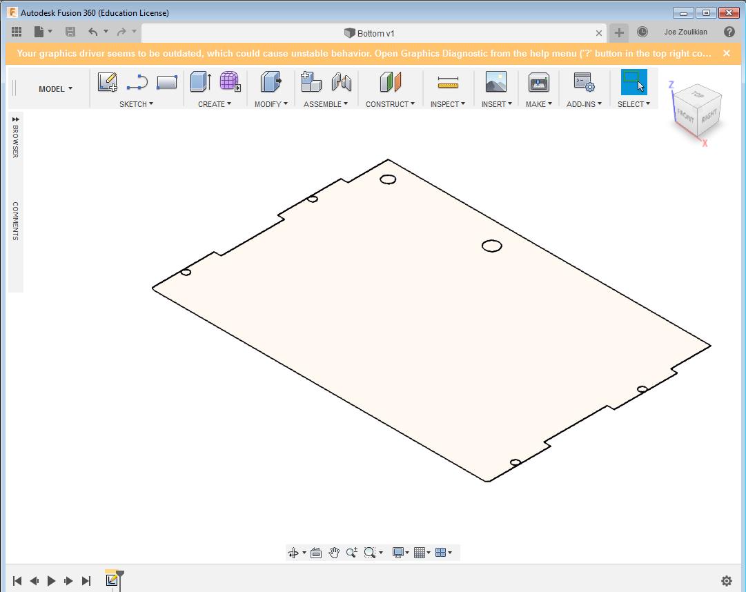
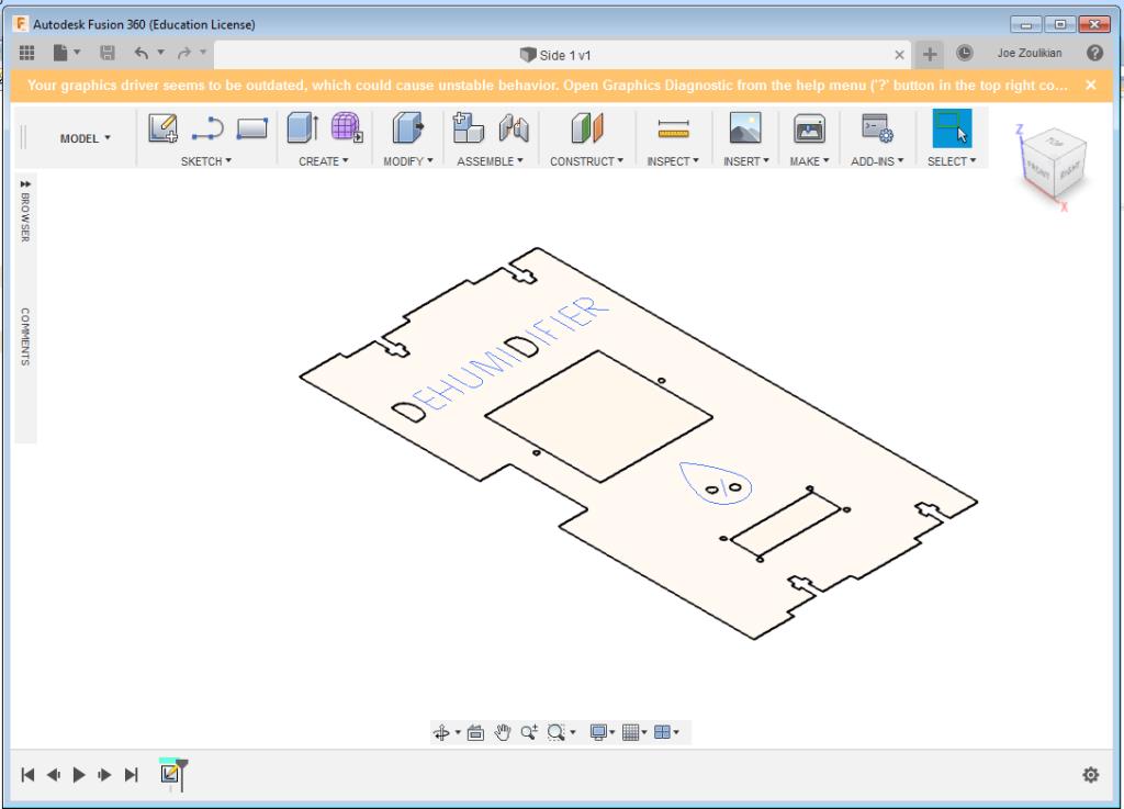
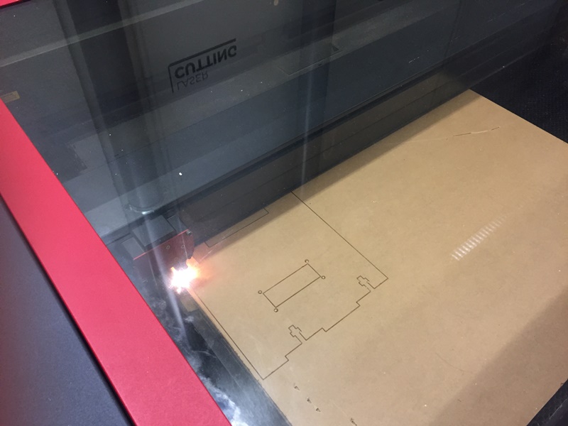
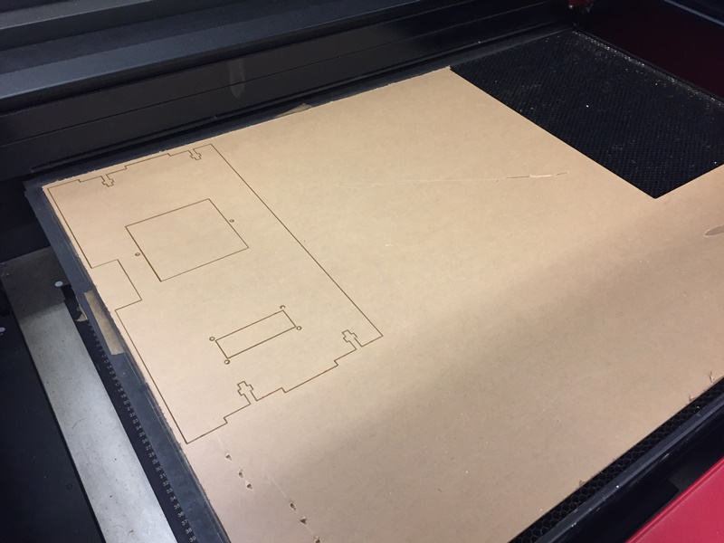
I designed the sides as well as the top and bottom walls for my "Dehumidifier" using the "Fusion 360" software.

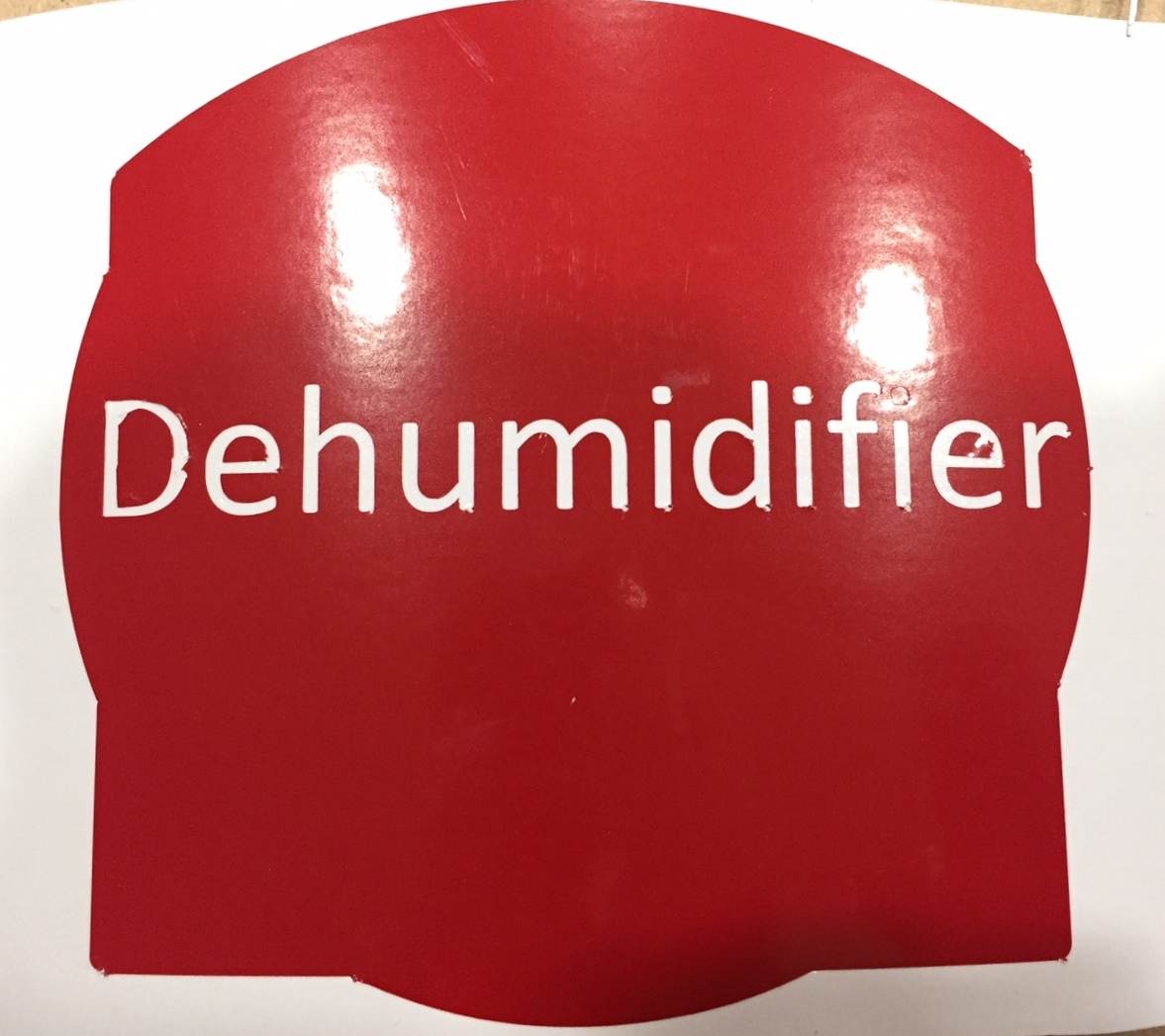
I designed a logo and cutted it using a Vinyl cutter.
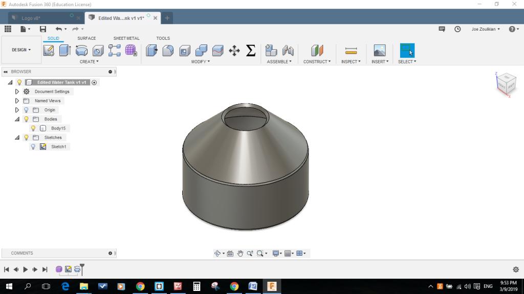
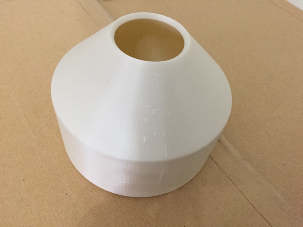
I designed and 3D printed the water tank that will collect the water generated from the Dehumidifier.
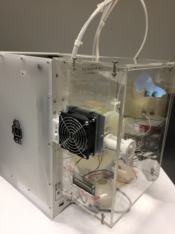
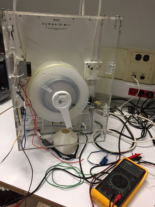
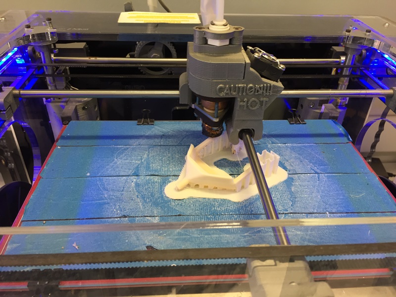
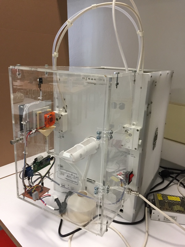
I designed, manufactured, assembled and attached the "Dehumidifier" to the "Ultimaker3-Extended" 3D printer.

.JPG)
.JPG)
Based on the knowledge I acquired during this chapter, later on I will design the final board using the Eagle software and the ATiny328 that will turn "On" the "Dehumidifier" whenever the Humidity exceeds the 50 percent.
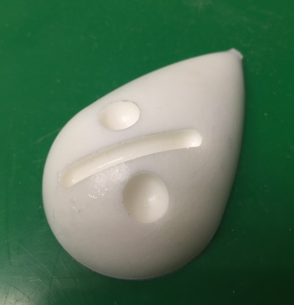
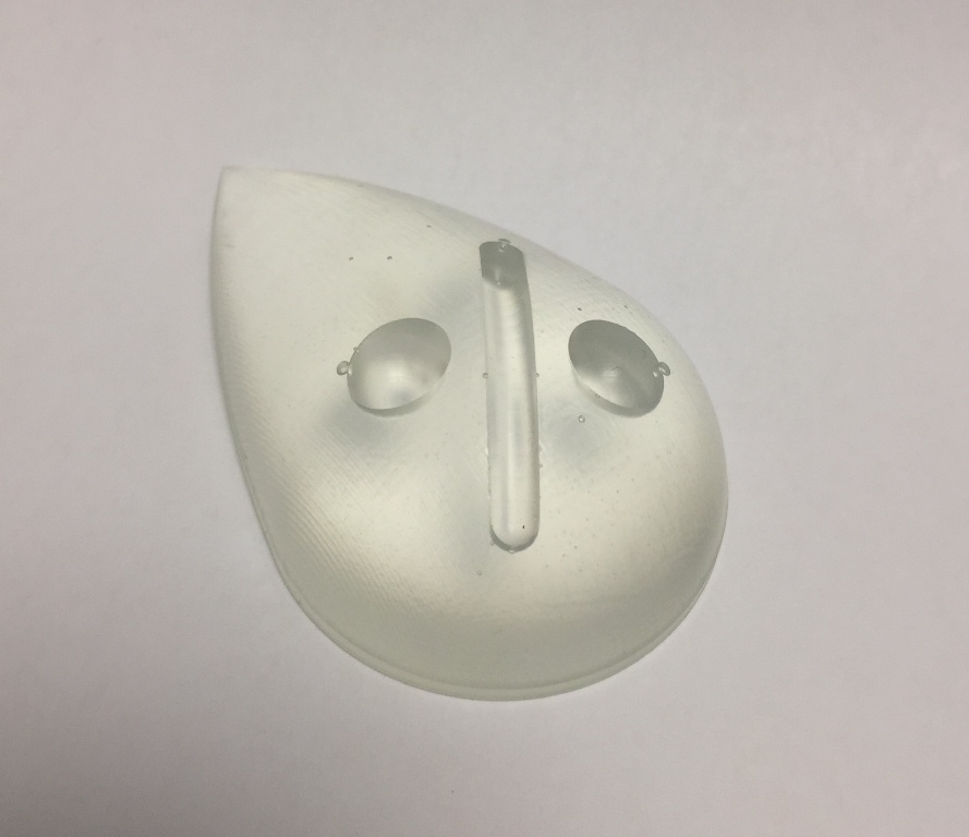
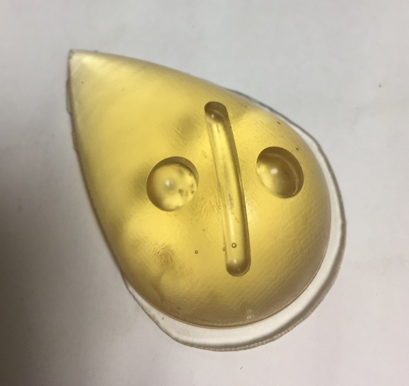
I designed, molded and casted a 3D shape of the Dehumidifier logo, I can attach it to my final box.
.JPG)
.JPG)
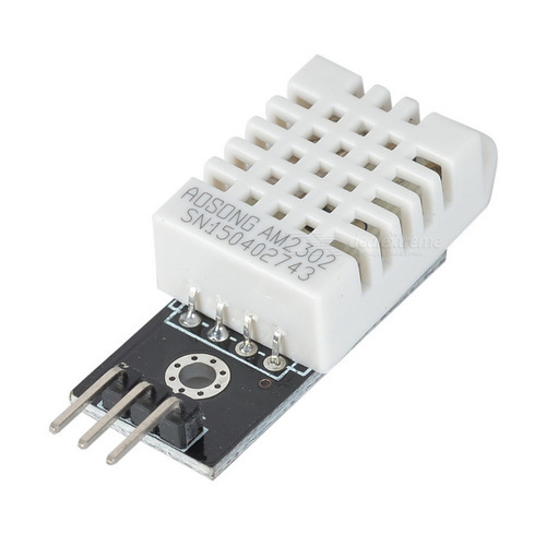
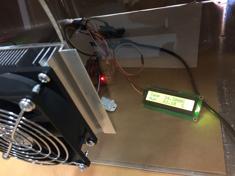
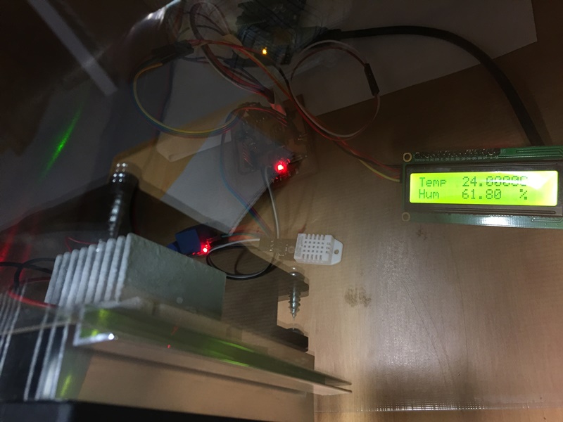
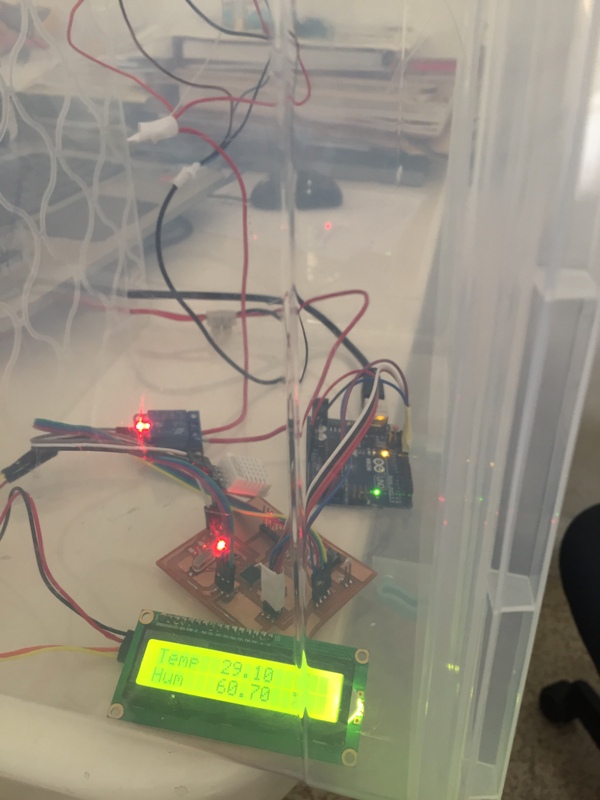
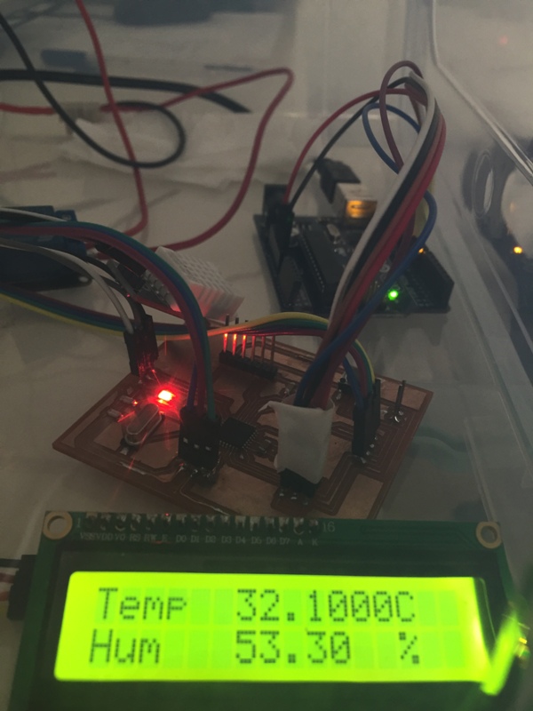
As you can see above, I connected the Humidity sensor "DHT-22" to Arduino to read the respective value on the screen, and when the Humidity exceeded the 60%, the relay (LED) turned on the Dehumidifier.
I will use the "LCD Display" and "The Rotary Illuminated Encoder" to control the LCD display.
Add a pic of the PCB with LCD and DHT-22.
During the Week 13, I summarized and answered all the below questions:
I can connect my system via a "Bluetooth" using "HM-10" to my Iphone to check the system online.
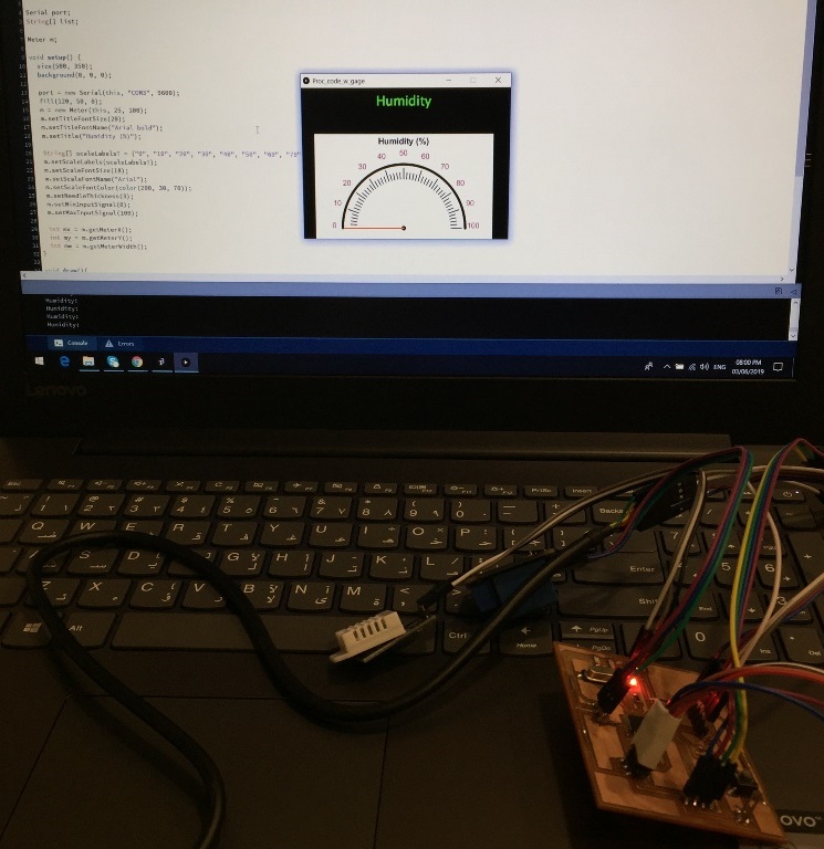
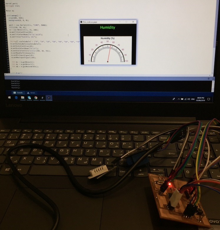
I can use the "Processing software" to visualize the "Humidity" level on my desktop, and check its status.
.jpg)
.jpg)
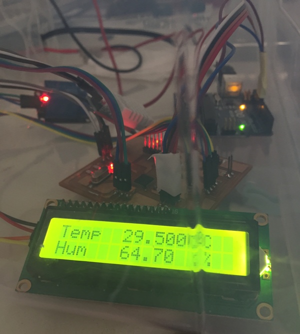
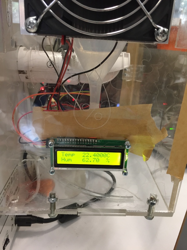
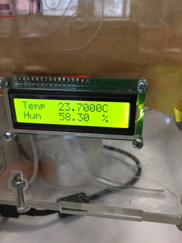
The Humidity is 61.1%.
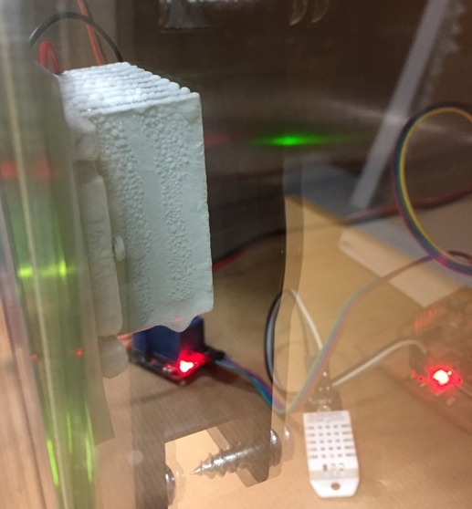
After 10 minutes: We can detect a small layer of ice on the heat sink.
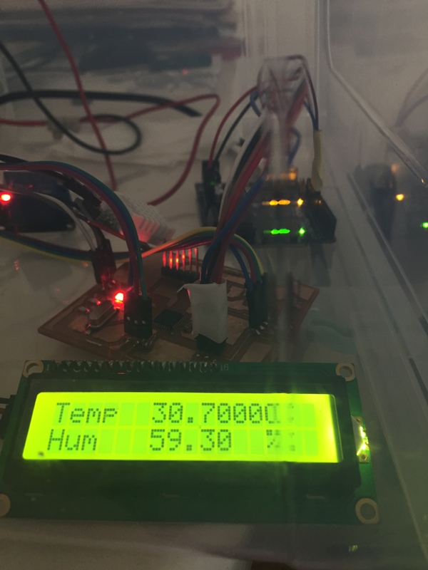
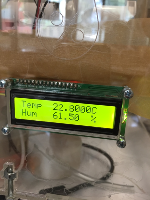
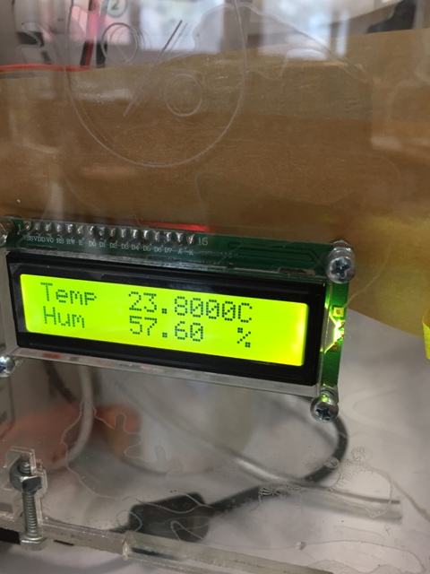
After 25 minutes: The Humidity reached 62.6%.

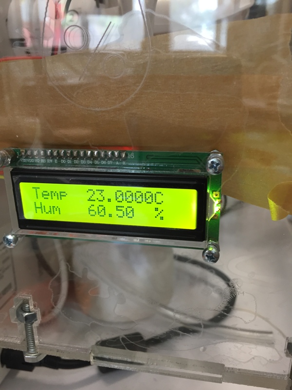
After 30 minutes: We can see the ice on the heatsink. The Humidity decreased to 61.8%.
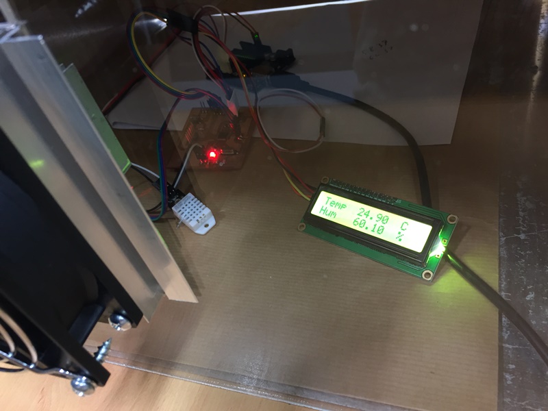
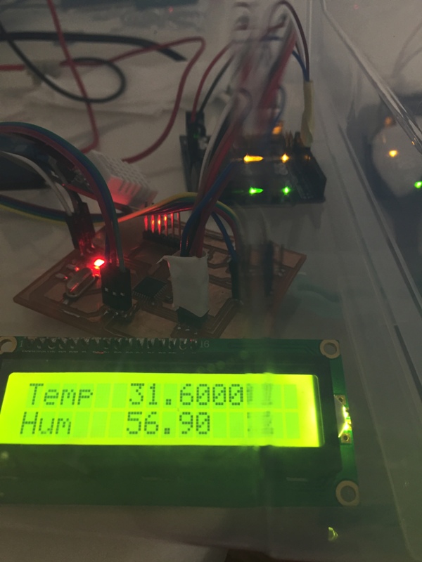
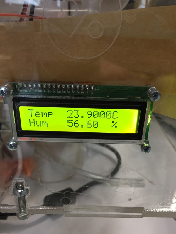
After 90 minutes: The Humidity reached 60.1%.
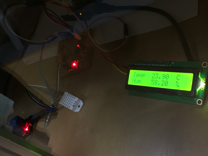
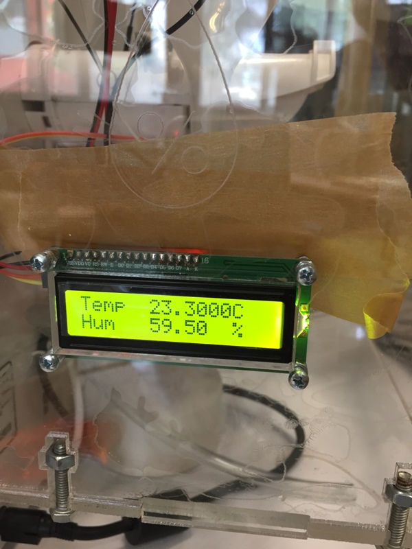
After 120 minutes: The Humidity reached 58.2%. We can clearly see that the ice is covering the entire heatsink.
I added a new fan on the cold heatsink back-side upon the recommendation of my advisor to produce an air circulation inside the box. As a result the layer of ice was not formed anymore but the result was not satisfying.
Other ideas and suggestions:
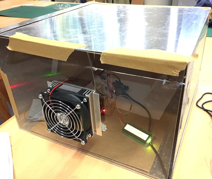
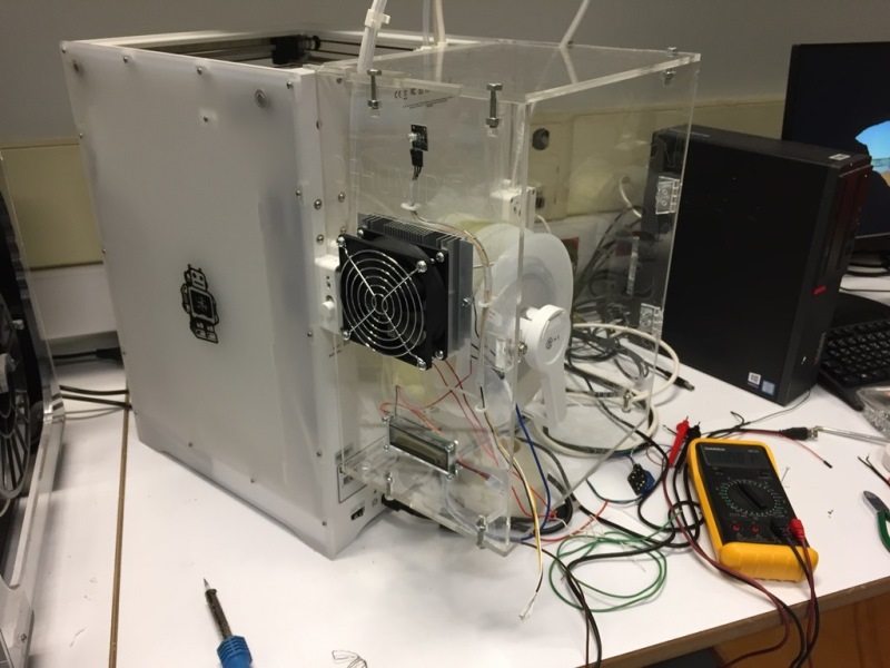
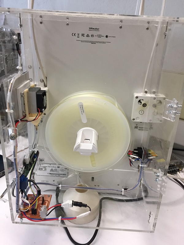
I fixed the "Peltier kit" on the right side wall of the new enclosure.
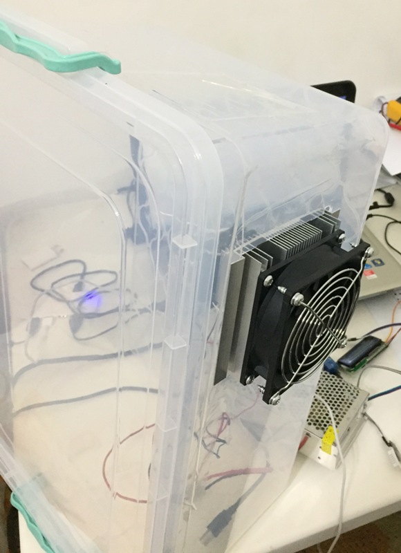
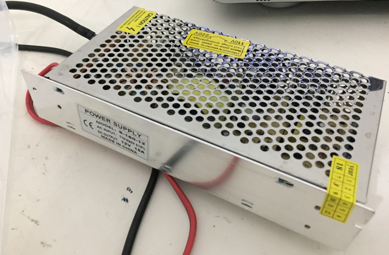
I am using an external 12 v 15Amps power supply.
I rotated the direction of the outer fan, that was fixed on the heatsink. It is blowing fresh air into the hot side of the heat sink. Previously, it was extracting the air from the heatsink to outside.
After 3 minutes:
After 7 minutes:
After 10 minutes:

After 25 minutes:
After 38 minutes:
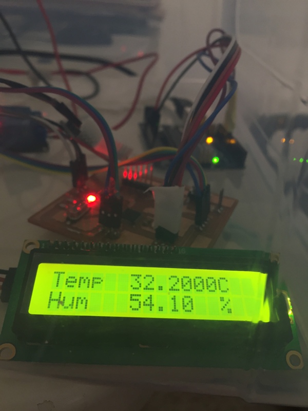
This operation was crucial, and as a result the humidity reached for the first time 53% which was not attainable in the previous tests.
To improve the operation, I should design and 3D print a funnel to facilitate the cooling of the condensed water around and inside the interior heatsink to an external tank by a pipe.
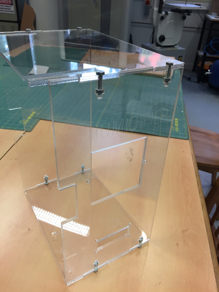
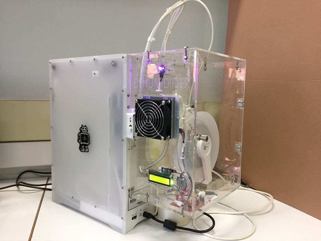
I redesigned and cutted the covers of the Dehumidifier box using 6mm Acrylic and the T-Slot technic that was very useful and easy to assemble and dismantle the box.

I attached it to the extended Ultimaker 3 and fixed the "Peltier" and the LCD screen
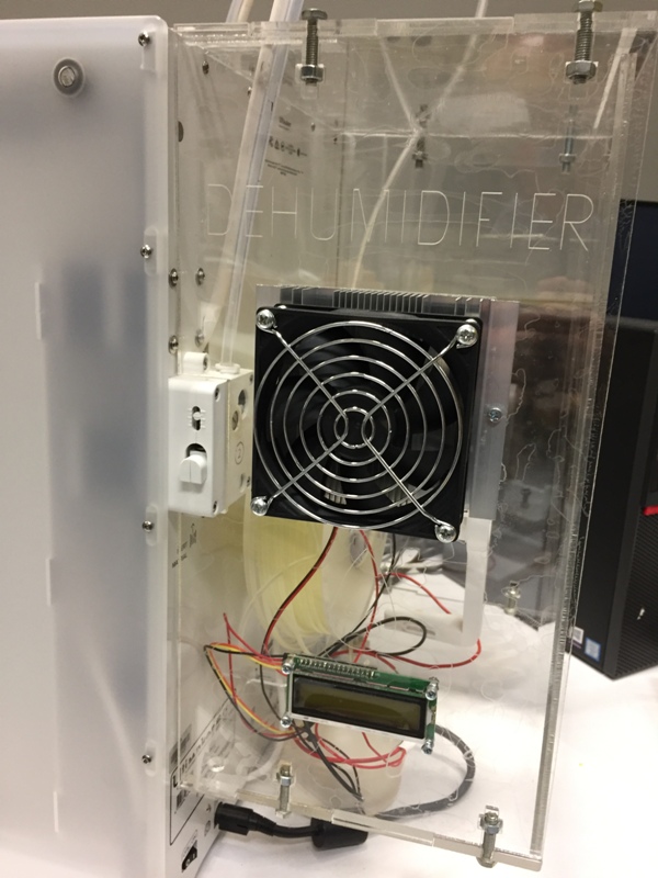
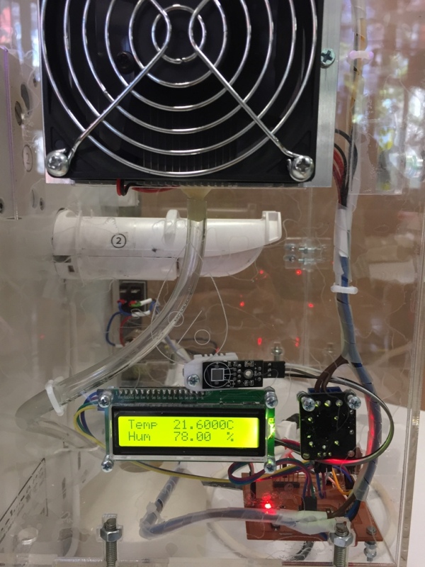
I checked the operation, as you can see I need to arrange the wires and fix the DHT-22, the Relay and the door. I added an On/Off switch and a power supply outlet easy to remove and having one way of connection to avoid polarity problems.
Before I arranged the wiring:
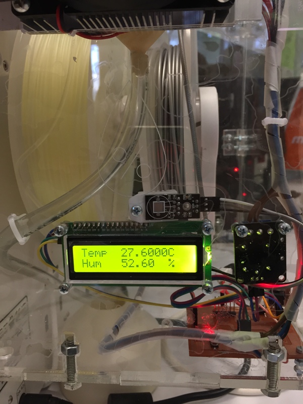
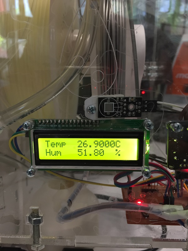
After arranging the wiring and designing and 3D printing a funnel to guide the water:

In around 40 minutes the Humidity level decreased from around 78% to 51.8%.
My Final Poster and video presentation are on Final Project page.
I liked to push the below video to see the full functionality of the "Ulti-Dehumidifier".
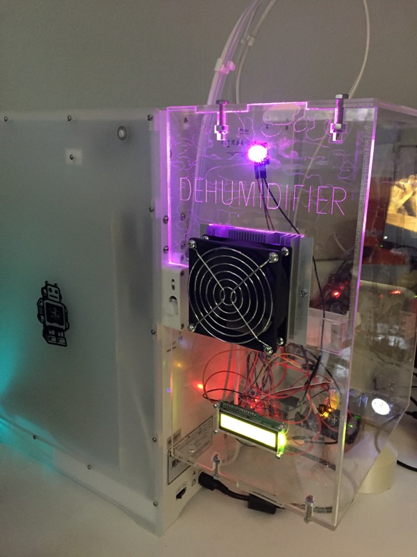
Berytech is located in the mountainous region so the humidity level is lower than the seaside. In the below video you can mention that we are reaching the limit of 50.00 %, the RGB LED light is magenta when the Peltier is "On" and the Humidity is over 50%, when it reaches the 50.00 % the "Peltier" will turn Off and the RGB RED will be red.
All my planed tasks have been completed. The problem was with the outer fan direction and the absence of the internal fan (40x40mm). When I changed the outer fan rotation direction and I added an internal fan on the cold side heat sink, I was able to reach humidity level very close to 50%.
For the future models, I should rearrange the "Peltier" and the PCB locations to facilitate more the PLA and PVA insertion to the 3D Printer.
I learned how to combine between the different software and high tech equipment's like Laser, CNC, 3D Printer to manufacture the necessary parts and use the specific electronic software and hardware in order to produce the needed PCB and program it to be able to operate the end product according to our plans and need.
At the end the result of the hard work will always be a successful product.
Edited Water Tank in Fusion 360,
stl file of the tank.
Arduino code,
AutoCAD Top of the box,
AutoCAD Bottom,
AutoCAD Door,
AutoCAD Side 1,
AutoCAD Side 2.

This work is licensed under a Creative Commons Attribution 4.0 International License.