During the eleven session dated March 27 2019, I was introduced to many types of input sensors:
The individual assignment is to measure something: add a sensor to a microcontroller board that we have designed and read it.
The Group assignment is to probe an input devices analog levels and digital signals.
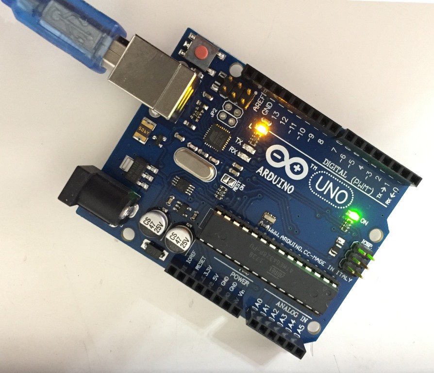
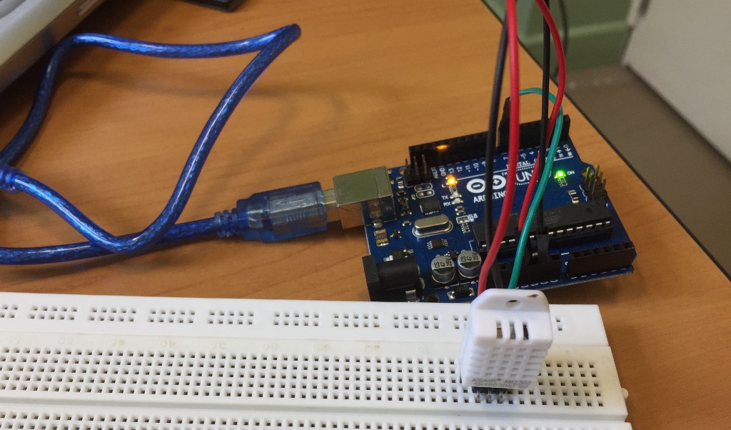
During the tests, I will use the Arduino Uno "Open Source" electronic hardware because it has the same microcontroller I will be using later on.
Connecting the Arduino to the laptop:
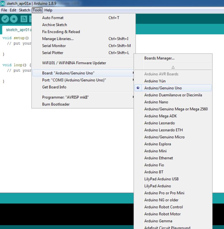
Inside Tools/ Board/ "Arduino/Genuino Uno" I will specify "Arduino/Genuino Uno",
When the board is connected:
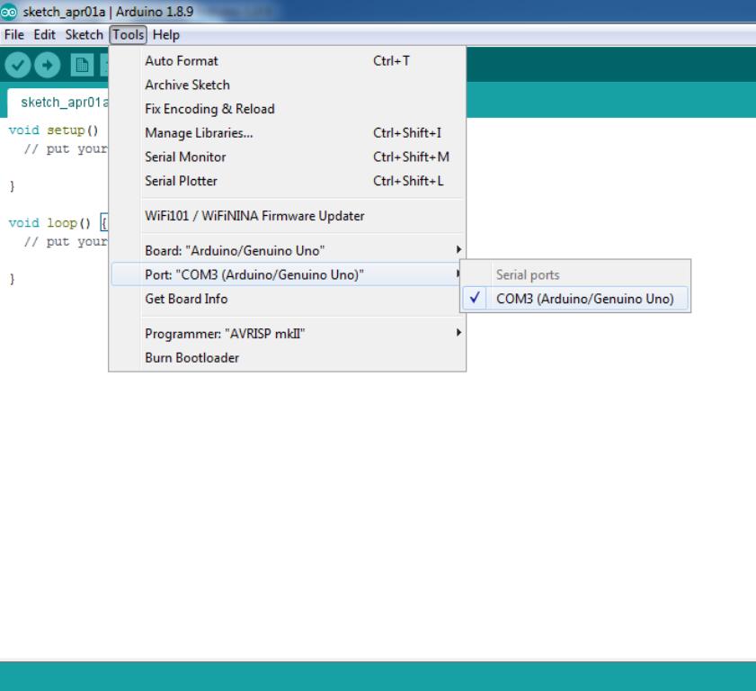
Inside Tools/ Port/ "COM3(Arduino/Genuino Uno)" I will specify COM3(Arduino/Genuino Uno).
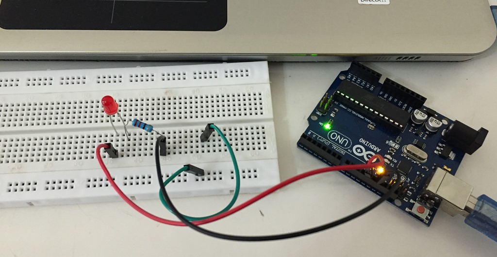
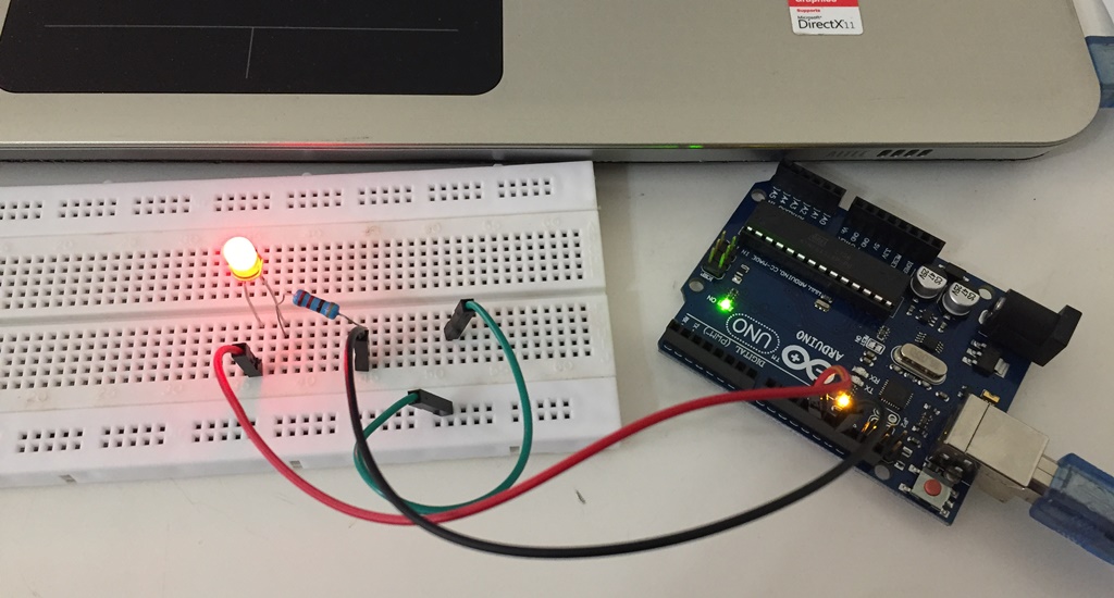
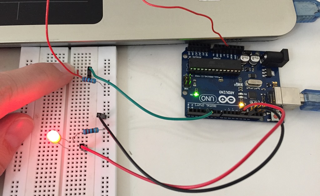
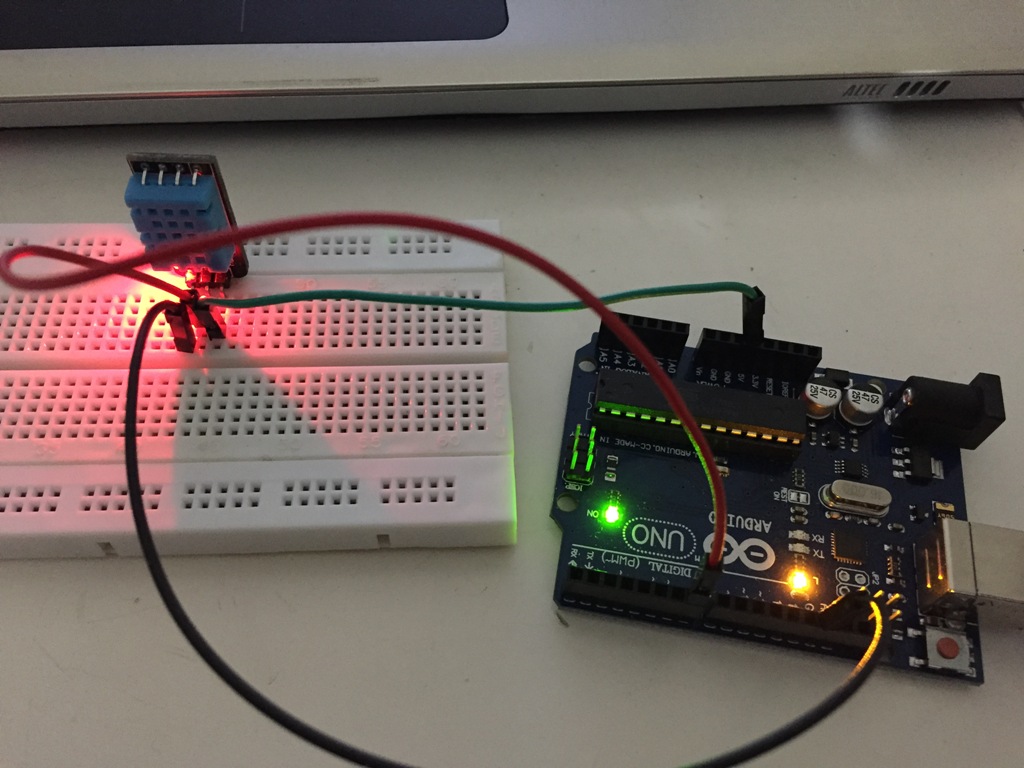
I watched several youtube video to be able to write and test the different Arduino Code. Before starting to install and test the Humidity/Temperature and CO2 sensors, I will start by commending a simple LED on the "Arduino Uno board" and then on a simple test board as well as a Push Button.
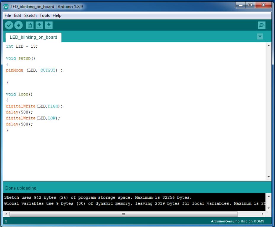
LED:
I wrote the below simple code on a new file of Arduino in order to test it.
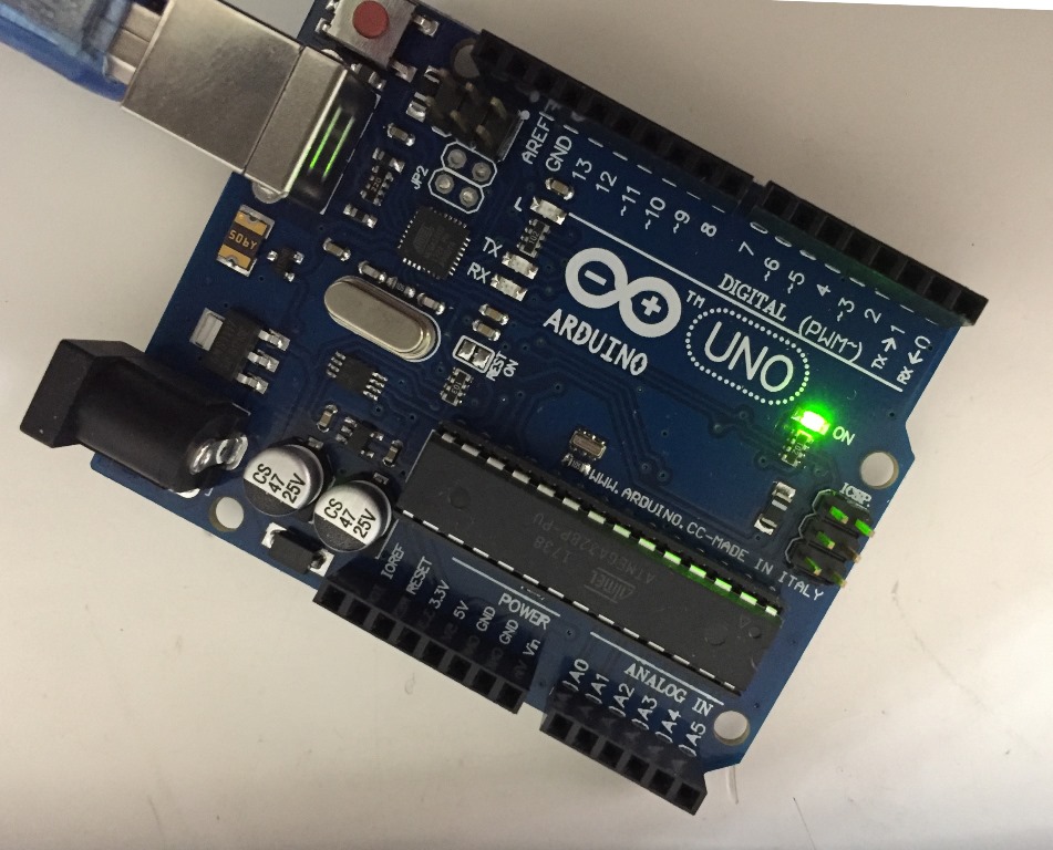
After that I test it on a test board.
The Gas Sensor(MQ-9) module is useful for gas leakage detection (home and industry). It is suitable for detecting H2, LPG, CH4, CO, Alcohol, Smoke or Propane. Due to its high sensitivity and fast response time, measurement can be taken as soon as possible. The sensitivity of the sensor can be adjusted by the potentiometer.
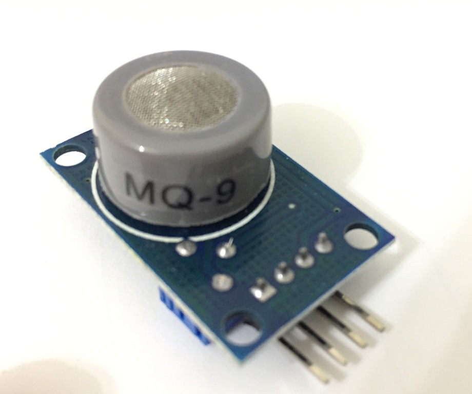
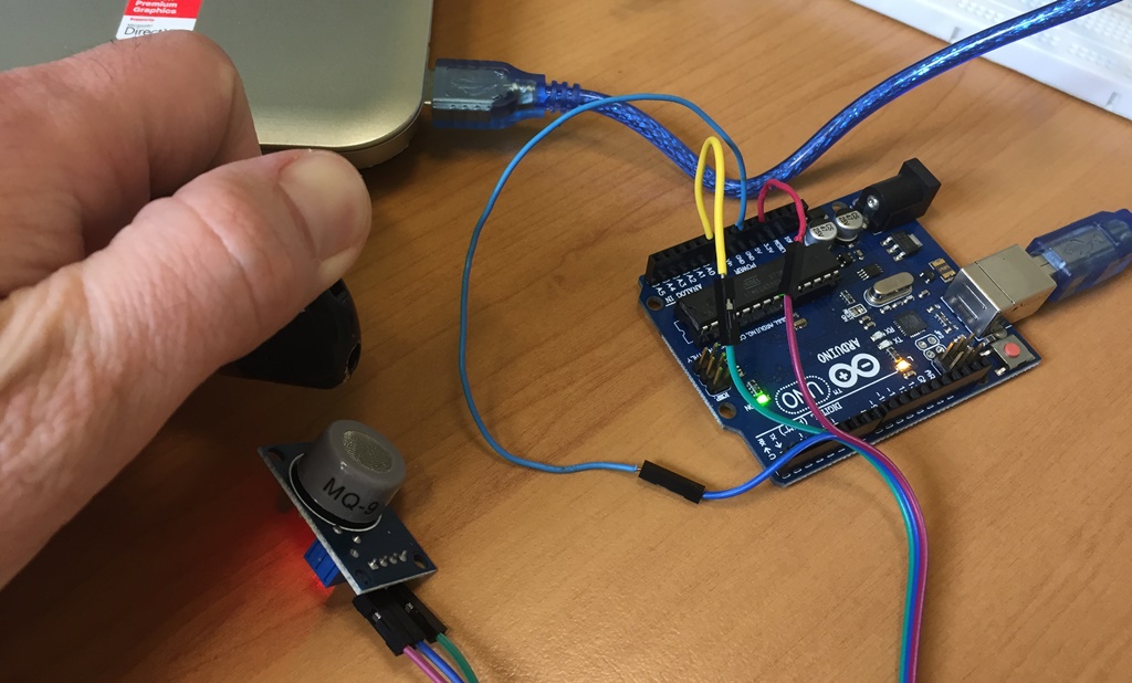
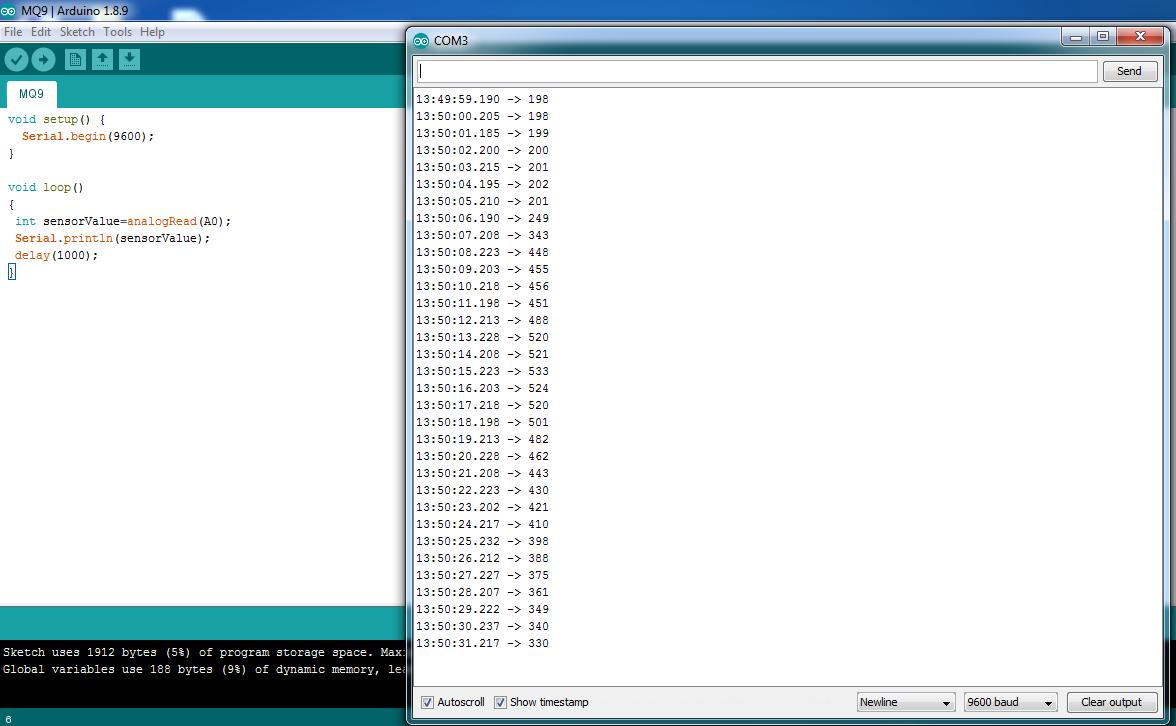
During the testing generated values were around 200, I blowed some gaz by using a simple lighter and the values reached 533.
CO2 Sensor Specifications
I will use the ATmega328P-AU Microcontroller, and a 16 Mhz Crystal since the Arduino libraries and codes are designed for 16 Mhz board. As per the requirement of the attached datasheet of the 16 MHz Crystal, I will use two 22pF Capacitors.
Data Sheet of the Crystal 16 MHz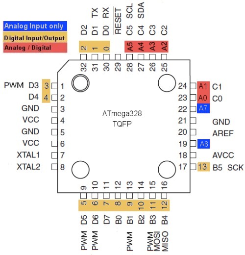
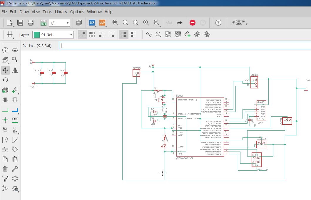
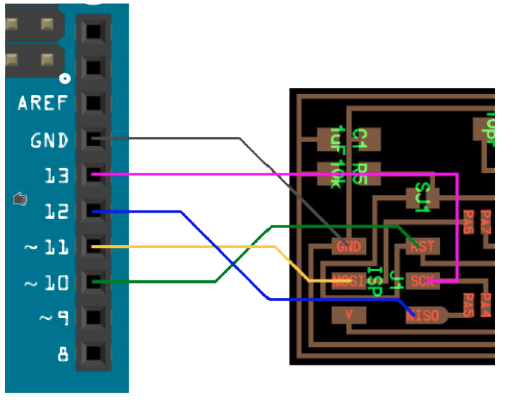
My schematic:
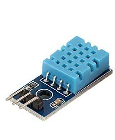
Knowing that I will use the "Humidity Sensor" DHT-22 and the Reset Push Button as Input sensors, I sketched the ATmega 328 Pin Out with its different below pins by respecting the different primary wiring first and according to the easiest path I selected Pin 1 and Pin 29 as Inputs.
Then I connected the remaining outputs and inputs according to the available spaces and in a way to avoid the short-circuit.
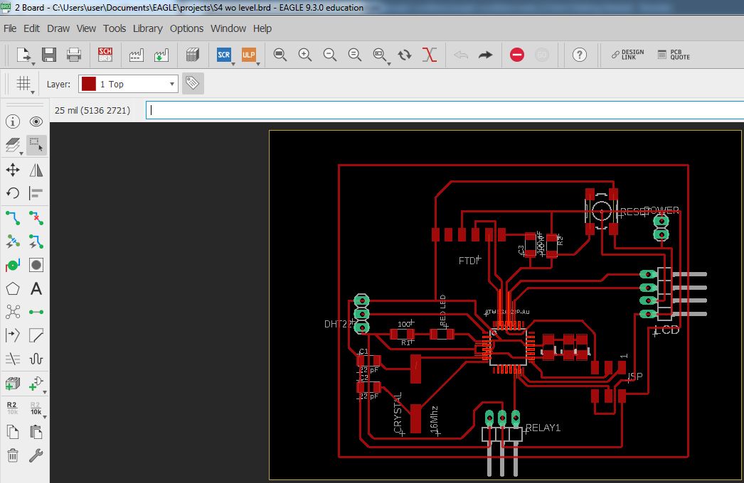
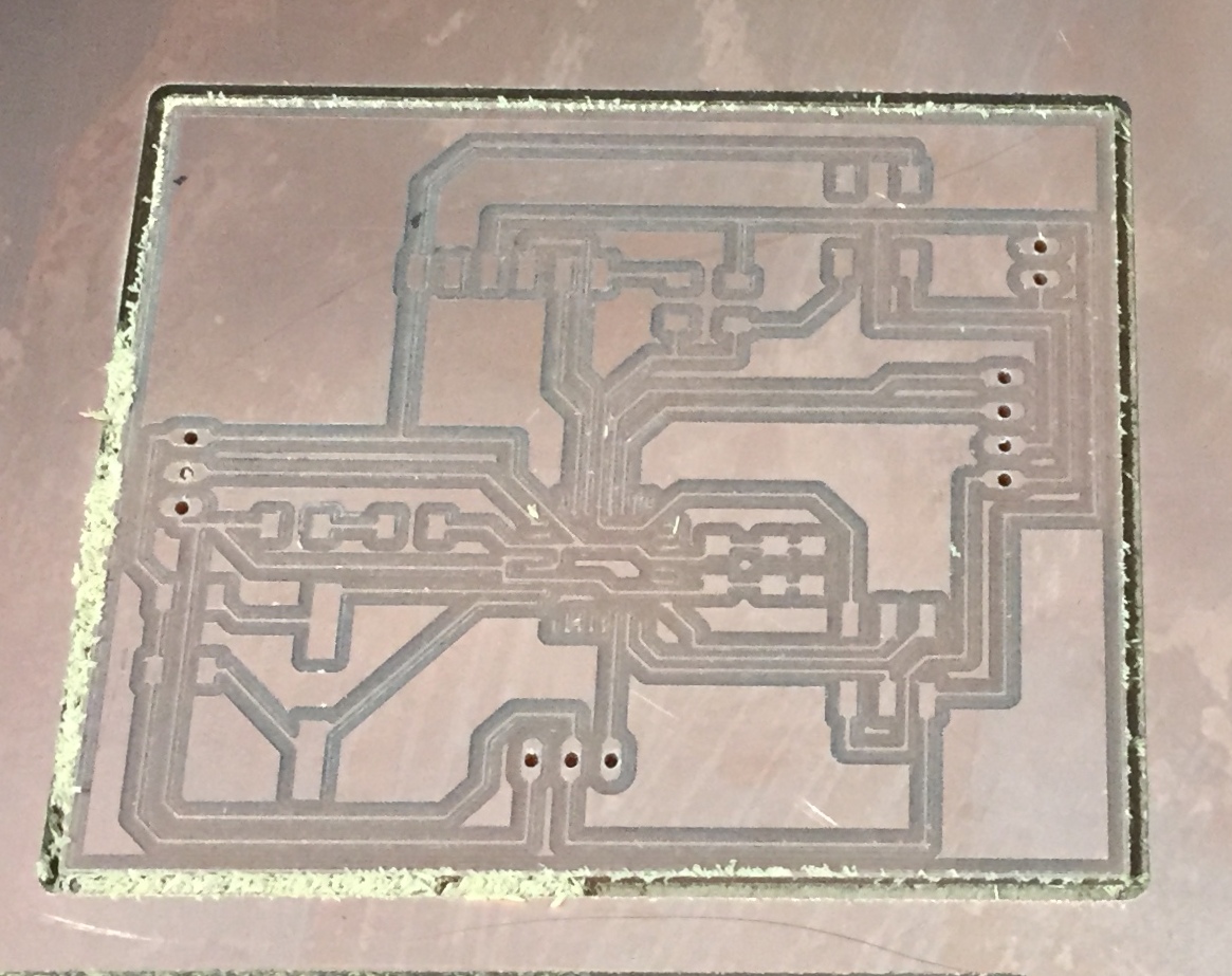
My Board:
During the design stage, I faced a problem because the "Eagle" software was always asking me to make a second connection between Vcc1 and Vcc2 and GND1 and GND2, just to mention that I had already made the first connection between Vcc1 and Vcc2 and GND1 and GND2 inside the Microcontroller.
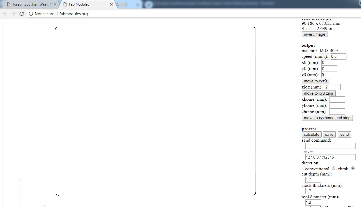
Preparation for milling my board:


The Toolpaths:
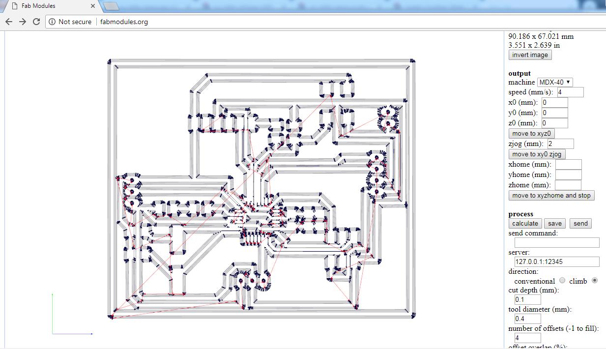
Milling my board:
Soldering Components:
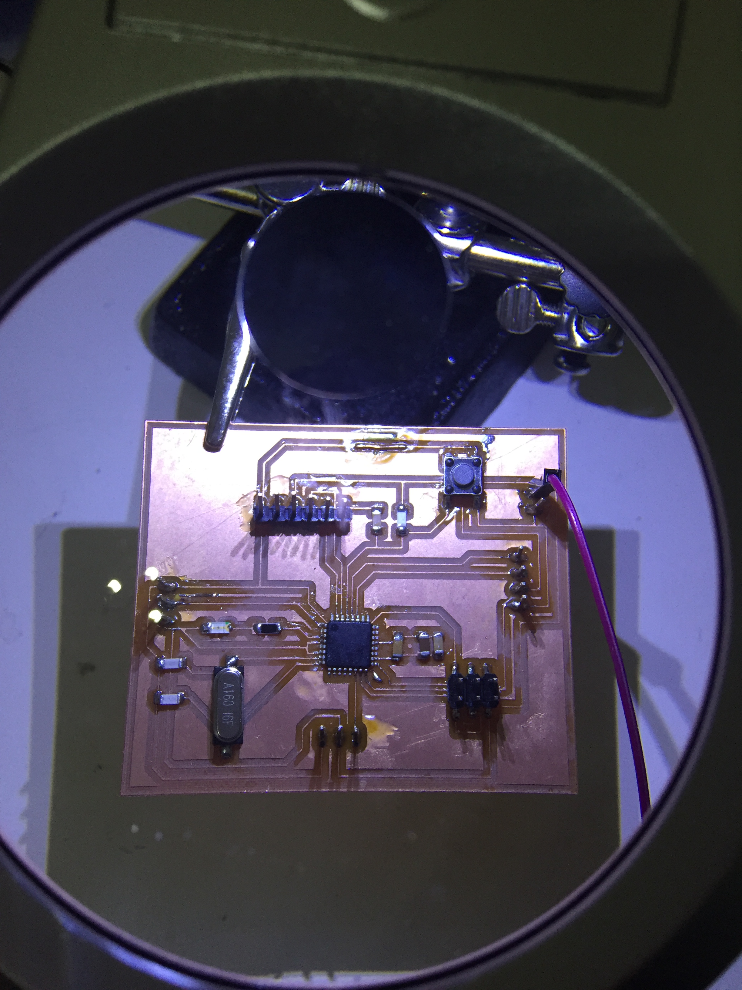
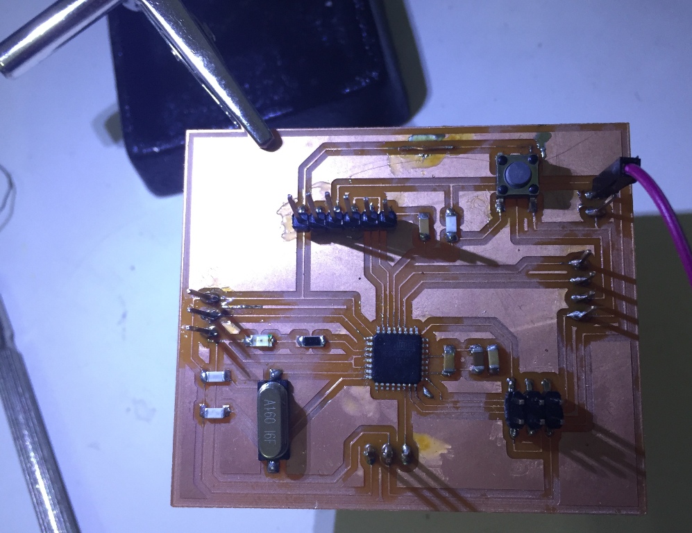
Wiring by PCB:
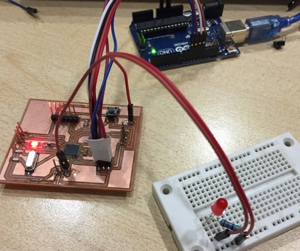
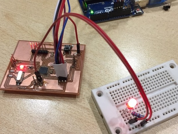
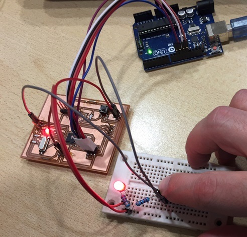
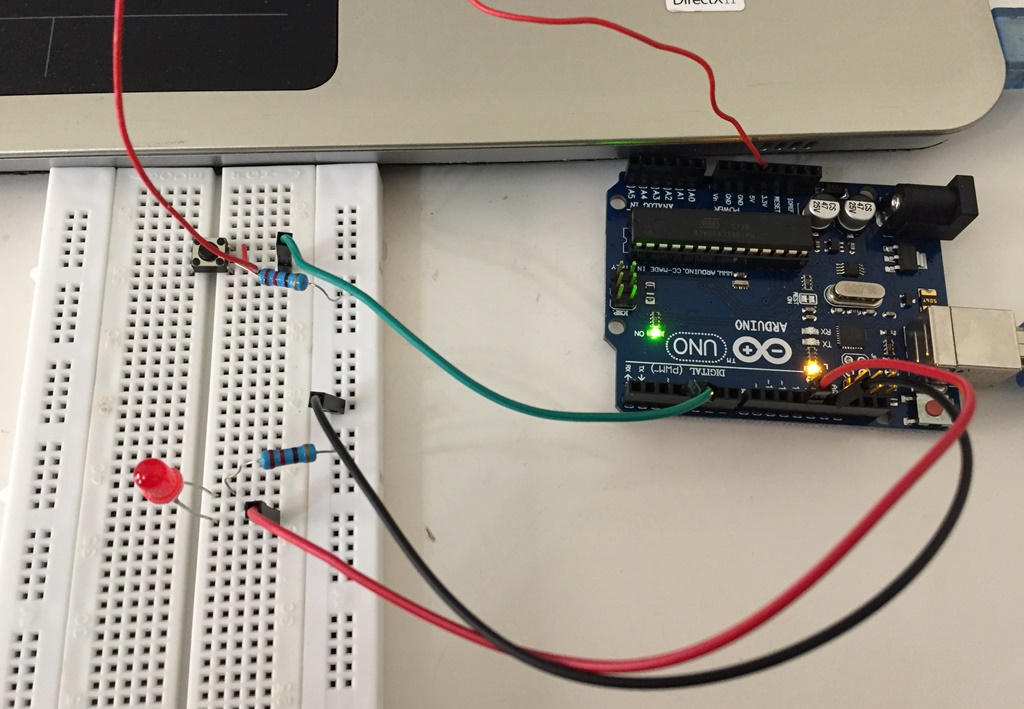
As you can see in the above pictures, when I press the push button, the LED will turn On.
.JPG)
.JPG)
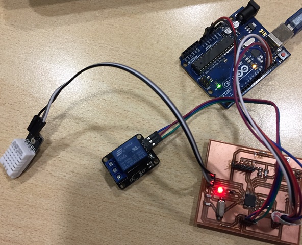
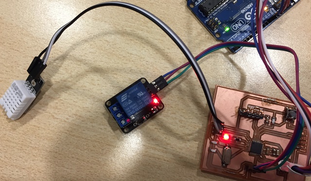
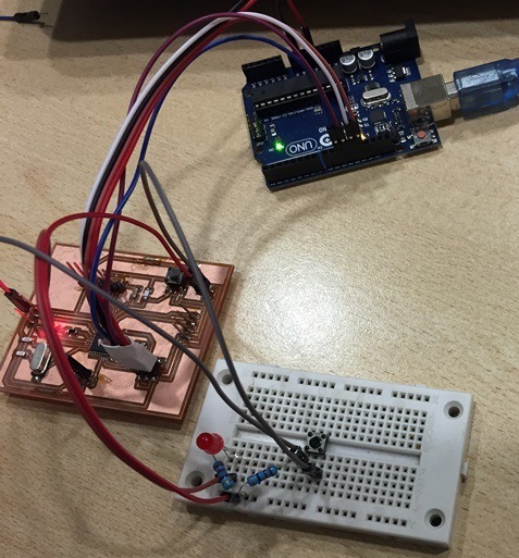
In the above pictures, I am using the humidity sensor DHT-22 to commend the output relay when the ambient humidity is above 60 %.
The group assignment is to probe an input device's analog levels and digital signals: we are going to read an analog input on the "Tektronix TBS1052B" Digital Oscilloscope.
For that we will use my friend's Nagis "Hello board" from Week7 Electronic Designon which we have an LDR.
I attached the code used.
As you can see, when we push the Button; If there is light than the Green LED should turn on, if not the Red LED should turn on.
To perform the test, we connected the Positive probe to the LDR and the Negative Probe the GND. Below we can see the values changing on the Oscilloscope screen depending on the light intensity.
The Arduino code for the LED On/Off,
The Arduino code for the Push Button
The Arduino code for the level sensor
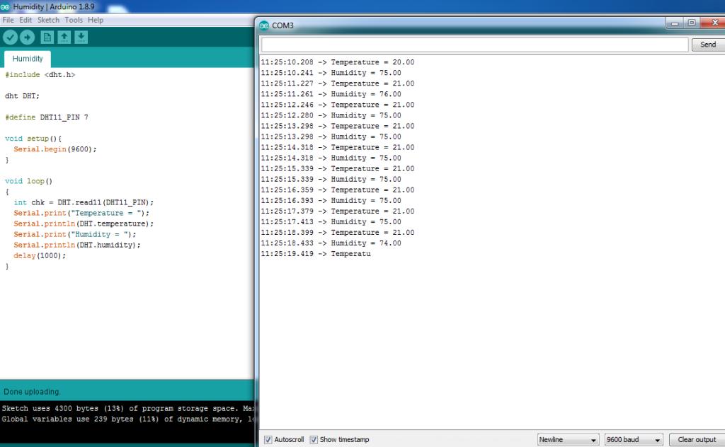
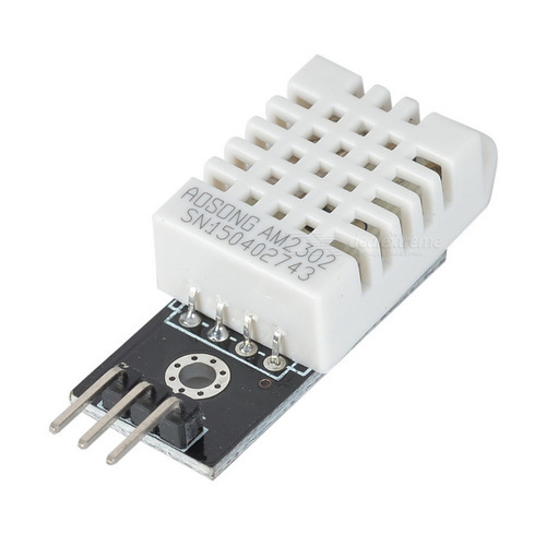
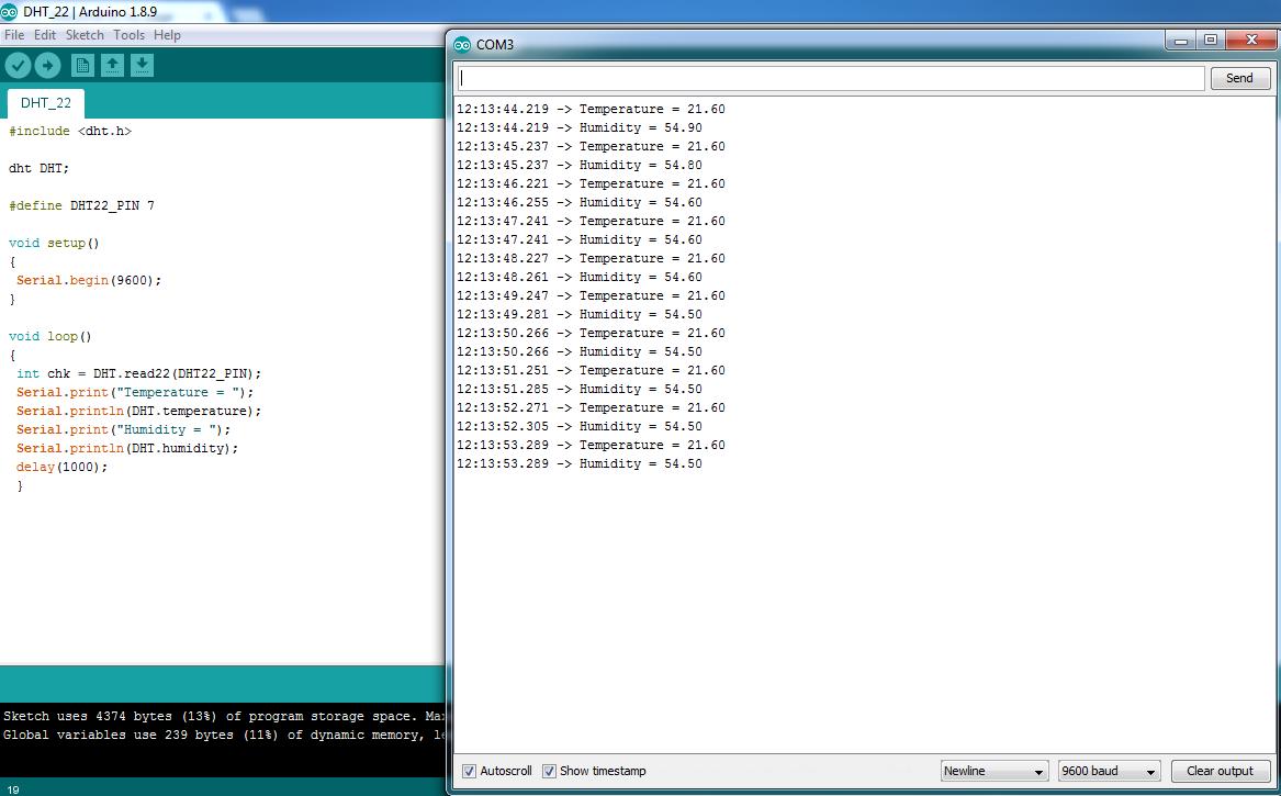
The Arduino code for the Humidity and Temperature sensor DHT-22
The Arduino code the Red and Green LED with LDR,
My board in Eagle,
My Schematic in Eagle,
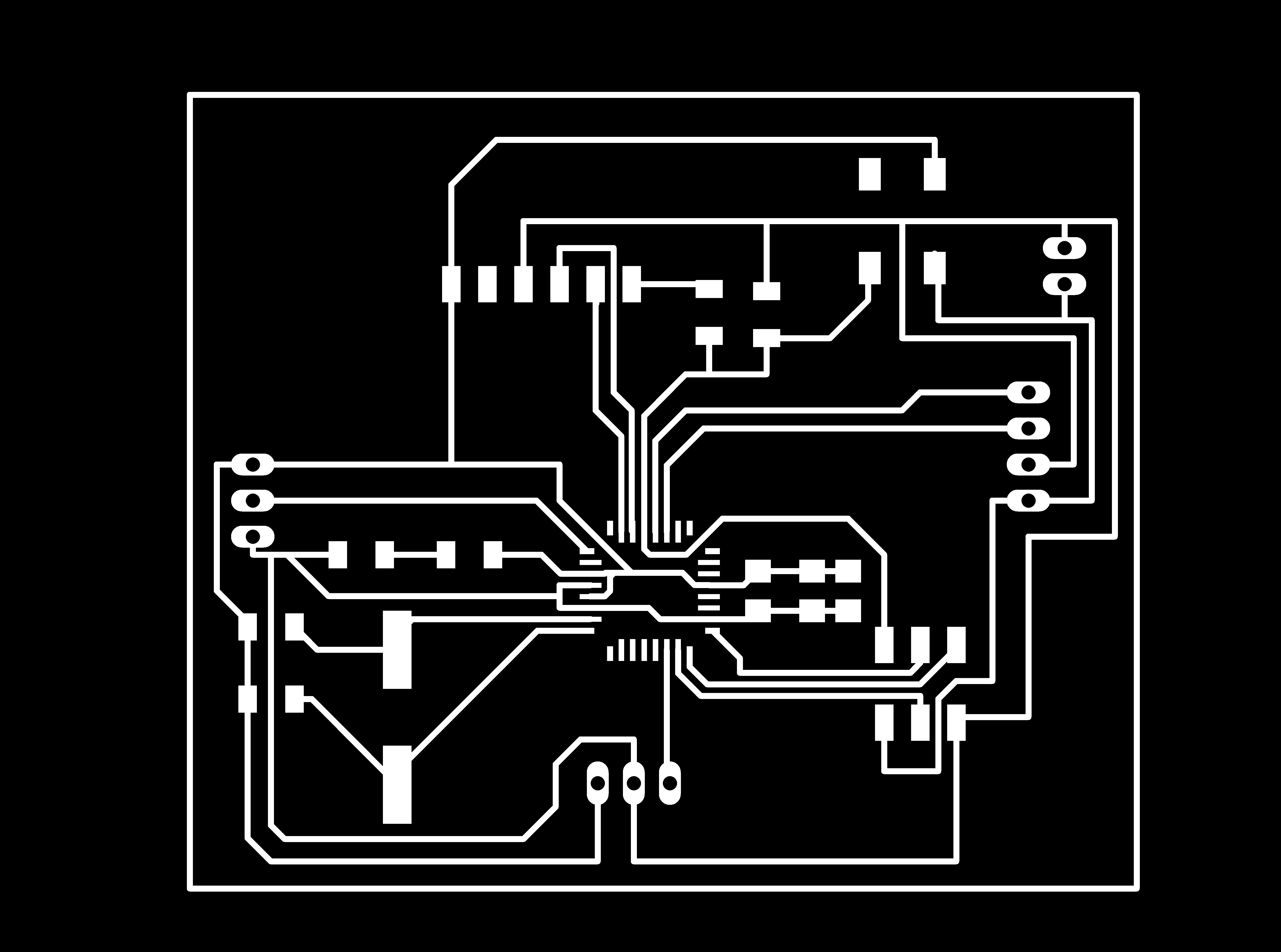
My board Cut out in PNG,
My board Final Design in PNG,

This work is licensed under a Creative Commons Attribution 4.0 International License.