Home About Me Final Project Fab Academy 2019 Berytech Fab Lab

Week 5: Electronics Production

During the fifth session dated on February 13 2019, I learned how to design a "PCB" (Printed Circuit Board) as well as how to produce it.

The group assignment is to characterize the specifications of our PCB productions. And the individual assignment is to Mill the FabISP and program it.


Characterize the specifications of the PCB productions

The first step to produce a new PCB is to design it. This design will be used later on to produce the board.
I will use EAGLE as my PCB design software.

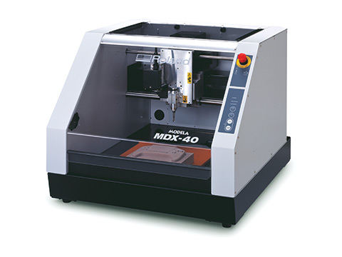
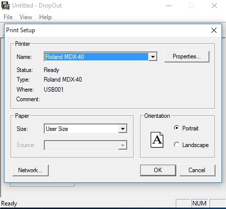
We used the Roland MDX-40.

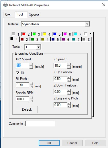
The output shape of the PCB can be affected by the following settings:

  1. The Rotation speed RPM Revolution Per Minute of the engraving tool bit,
  2. The tool bit diameter,
  3. The Feed rate (the speed of the bit moving in X and Y directions),
  4. The Offset Number is the number of passes done by the bit.

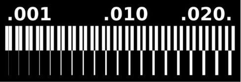
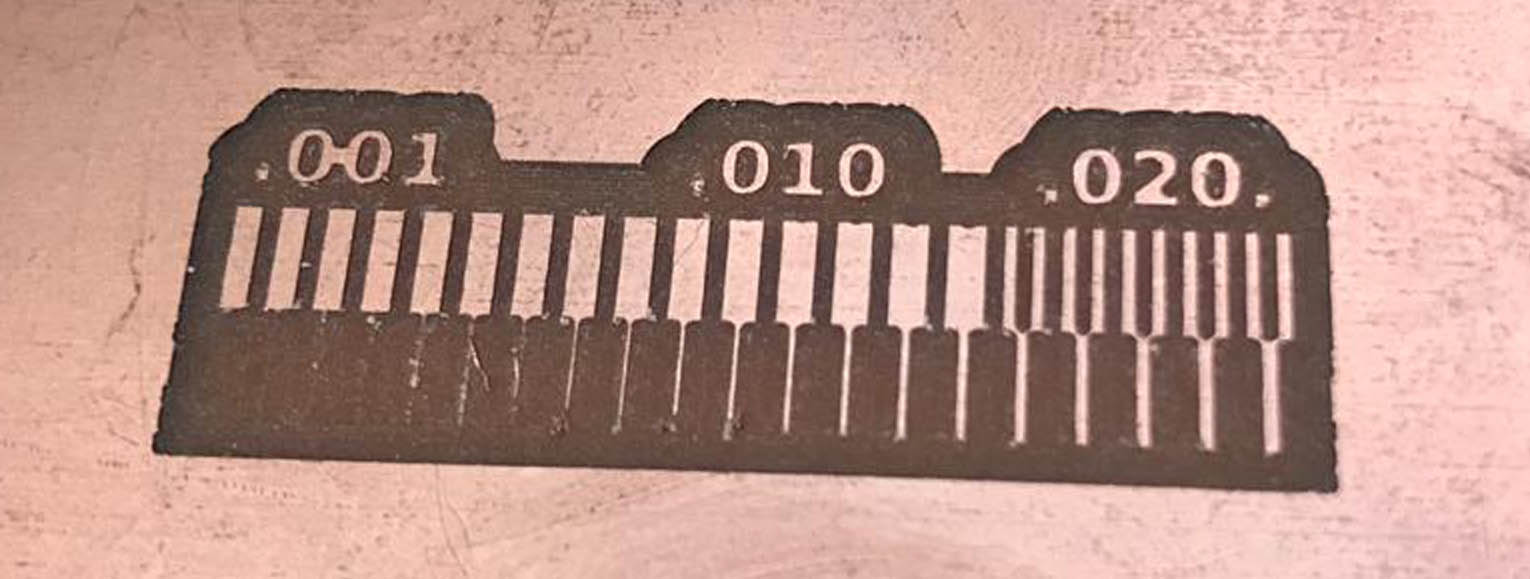
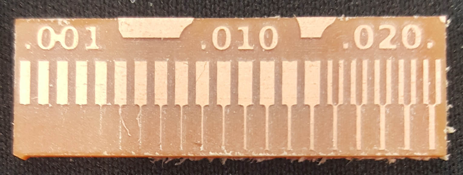
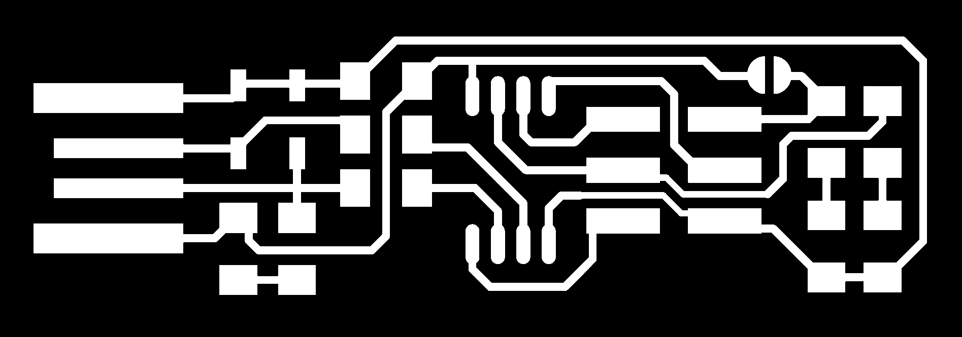
In order to characterize the design rules for the PCB production, We have to do the line test. This test will enable us to check the range of the line thickness that the milling machine can mill with a specific tool bit.


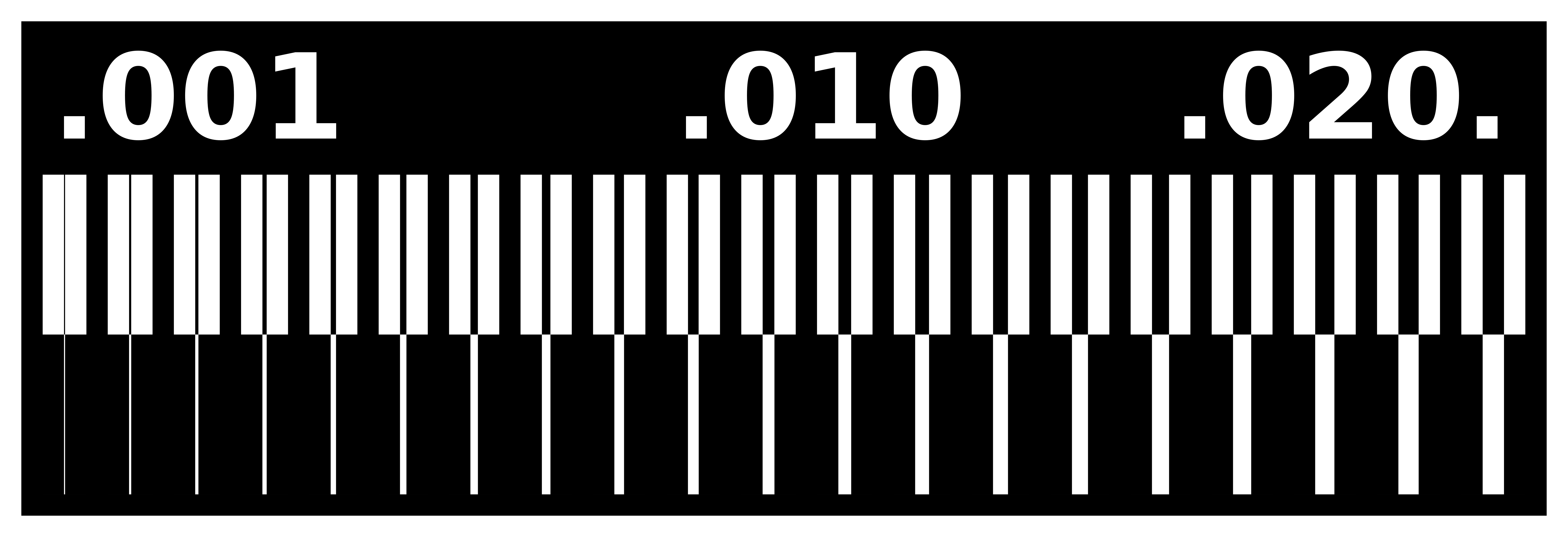
As a general rule we must open the above image in an image editor (Gimp, or Photoshop),


Generating the .gcode:

By using the "Fab modules", we will calculate the .gcode that is a programming language which translates an image into coordinates and instructions for the CNC machine, to do that:


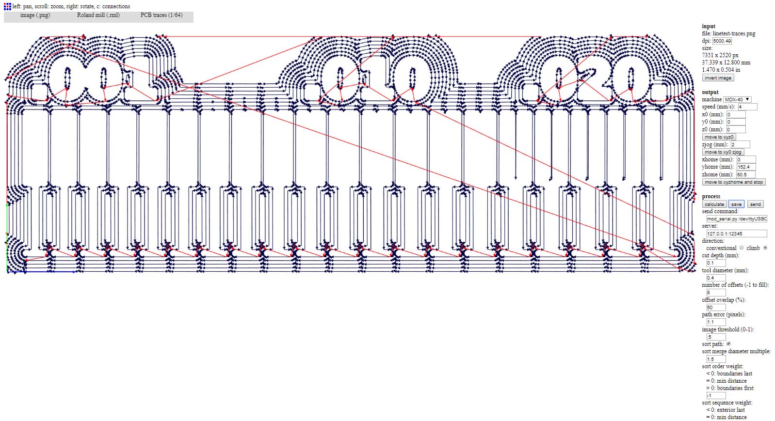
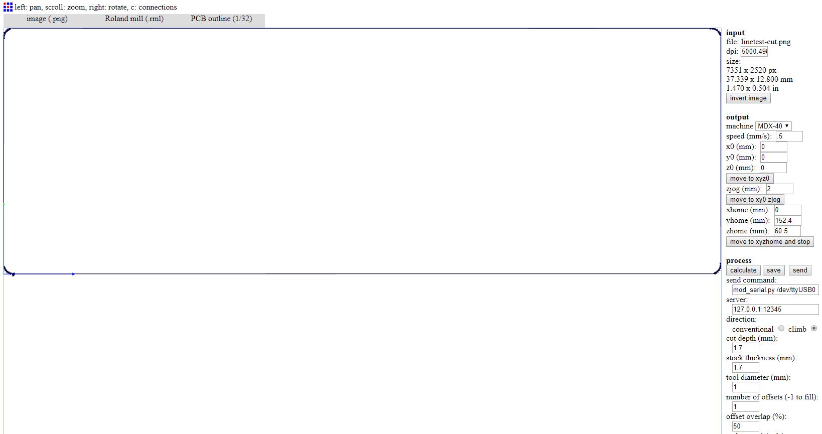
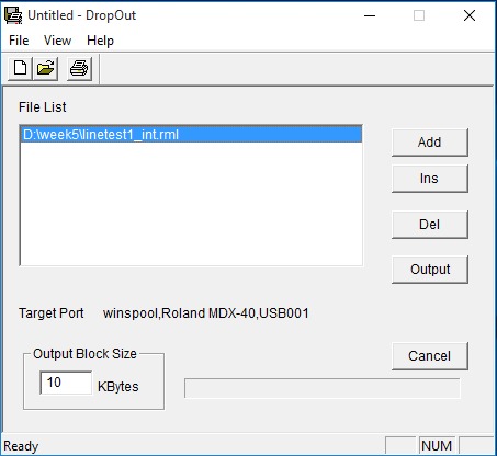
After generating the .gcode, we have to insert it in the Droupout software of the Roland CNC mill, and after homing the CNC we will press output in order for the machine to start the job.


Individual assignment mill and program the FabISP:

I used the Brian's design.

The Schematic:

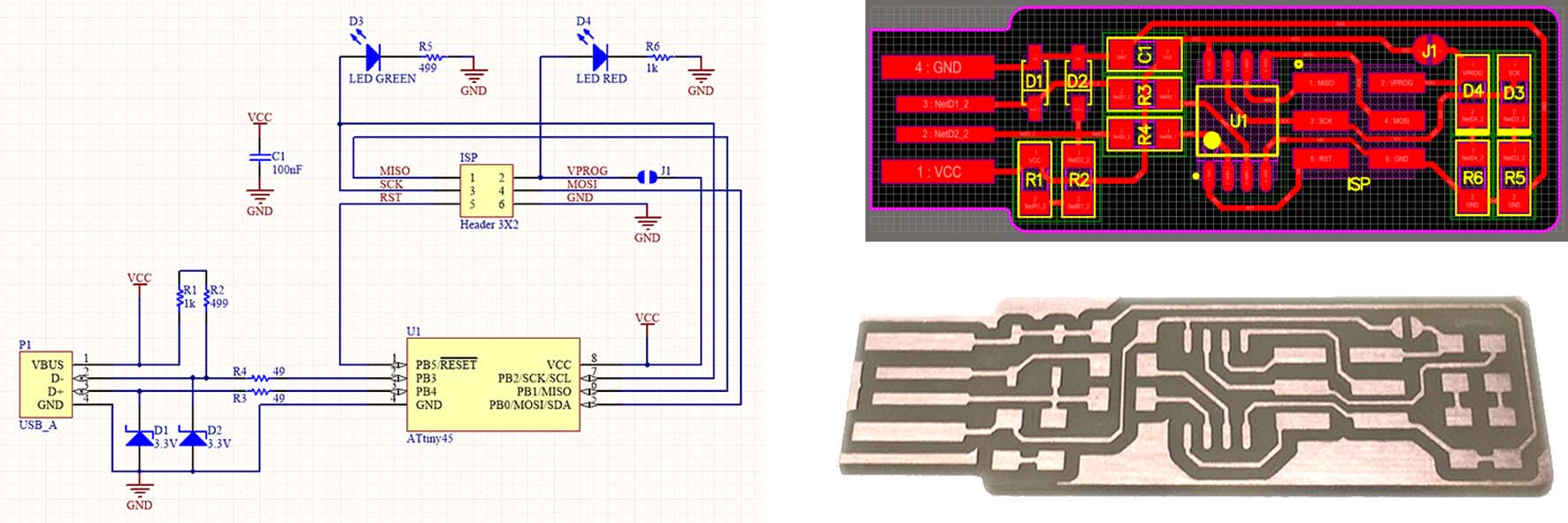
In order to produce the FabISP I have to CNC mill it. For that I need two pictures to generate the .gcode:

  1. One for the internal path of the PCB that can be downloaded from the link: Traces(1000 dpi),


  2. And one for the external path of the PCB that can be downloaded from the link:Outline Cutout(1000 dpi),

To generate the .gcode, I will follow the same steps as mentioned above.


Engraving:


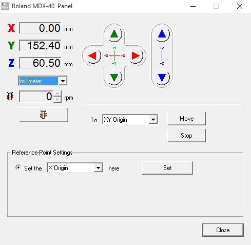
Zeroying the tool Z offset, and the XY Origin:


Soldering the components and Testing the board:

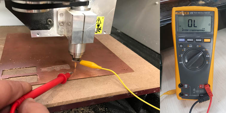
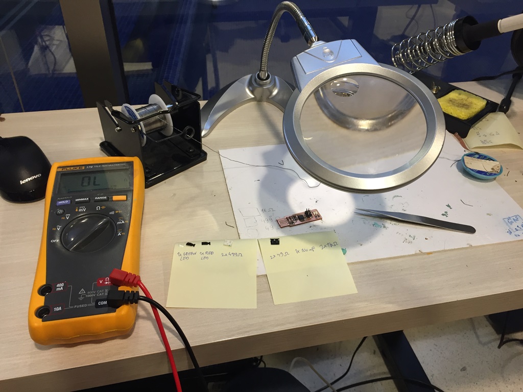
Before starting the soldering and after soldering each of the components, I tested the board with a multi-meter to check if there is any soldering or short-circuit problems.
I checked the polarity of the LEDs and Zener diodes that must be installed in the correct direction.

I used the following components based on Brians design:

  1. 1x ATtiny85
  2. 2x 1 kOhm resistors
  3. 2x 499 Ohm resistors
  4. 2x 49 Ohm resistors
  5. 2x 3.3v zener diodes
  6. 1x red LED
  7. 1x green LED
  8. 1x 100nF capacitor
  9. 1x 2x3 pin header


Programming my ISP:

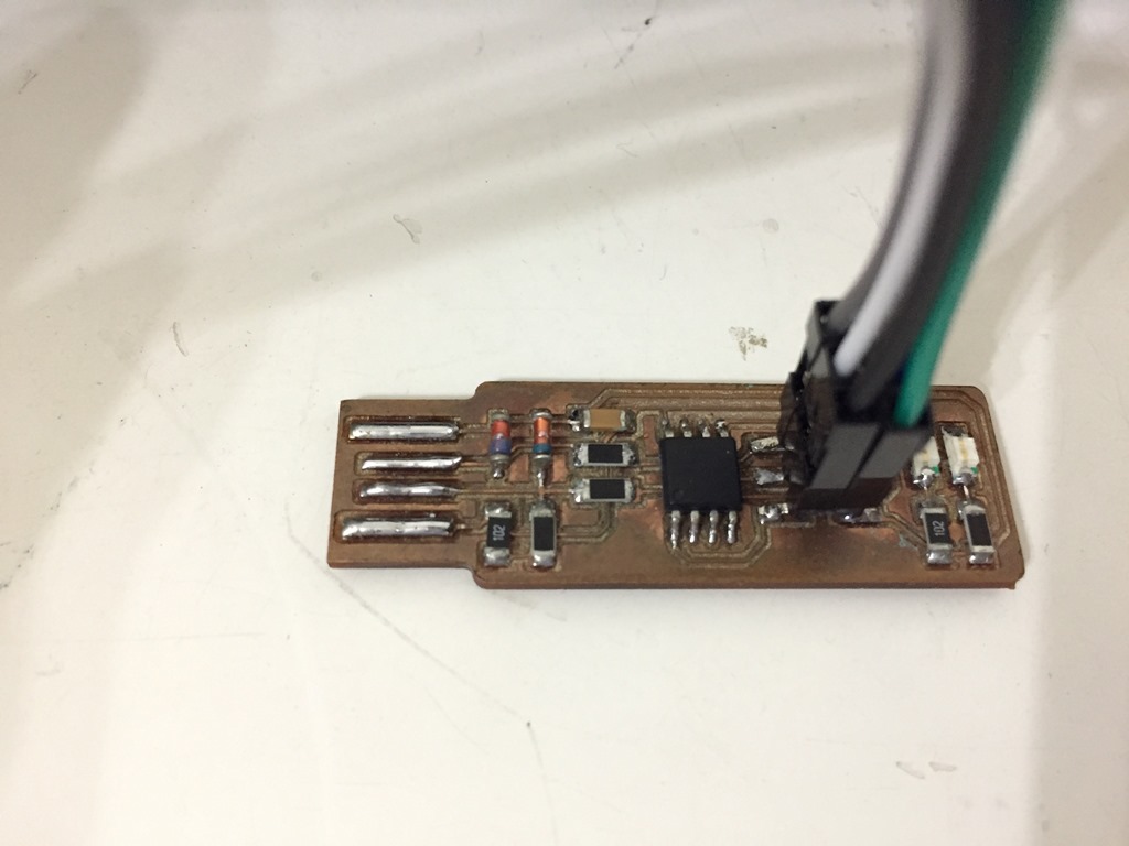
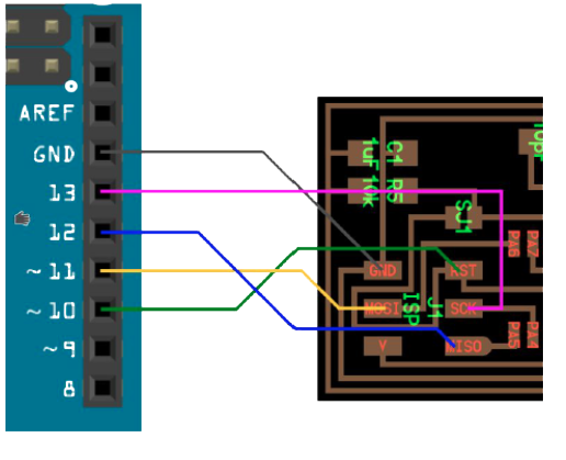
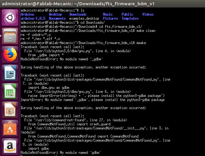
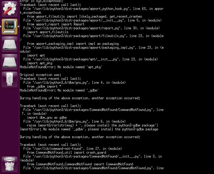
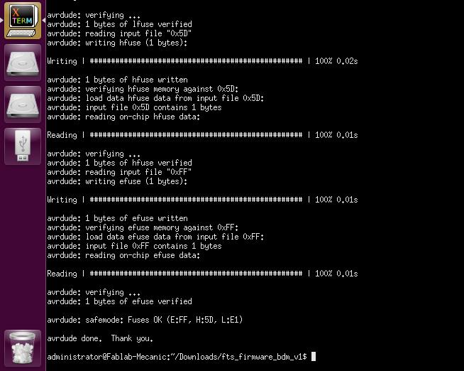
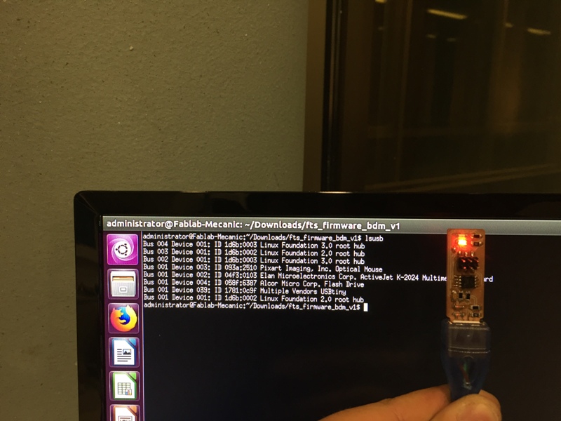
I followed the below steps to program my ISP:

  1. I downloaded and opened the Arduino IDE,
  2. I connected Arduino programmer to the PC,
  3. I selected the specific Port (COM) and Arduino Uno in (Tools),
  4. I selected ArduinoISP in (Files) /(Examples), and uploaded it,
  5. I connected the Arduino to my PCB through the below ISP wiring,


  6. I edited the makefile with the MCU type(ATtiny 85), Programmer(stk500v1), and Port:(/dev/ttyUSB0)
  7. I download the provided firmware and extract the zip file,
  8. I opened the command prompt in Linux and go to the code directory,
  9. I entered the commands to generate a make file:make clean, make (as shown below):


  10. I opened the "Make file" with Brackets and replace MDU=ATtiny45 by MDU=ATtiny85 and saved the file,
  11. I entered the following commands to load the program on the ISP: make fuses, make flash as shown below.

  12. I disconnected the ISP from the Arduino and plugged it into the PC.
  13. I typed lsusb, I should read Multiple Vendors USBtiny.

  14. After verifying that my ISP is recognized, the last step is to make its programing irreversible and to set the Reset Pin as GPIO. For that end the command is: make rstdisbl.


  15. Hero Shot:


    Downloads:

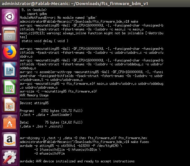
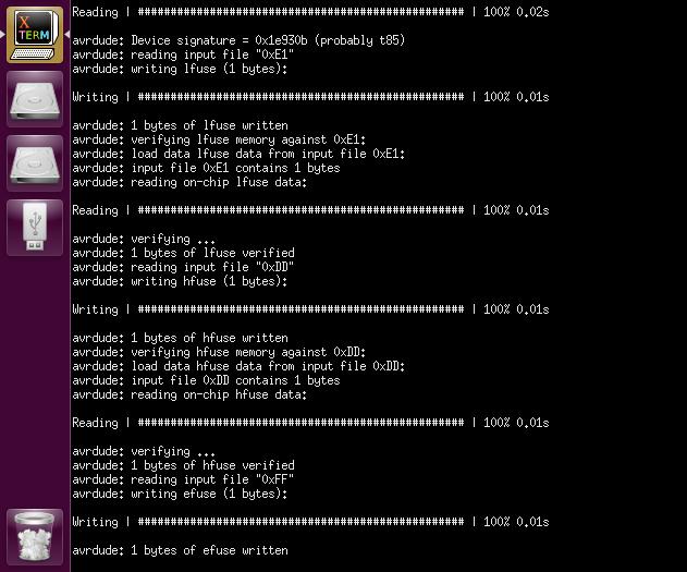
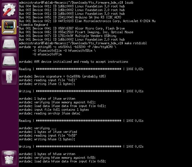
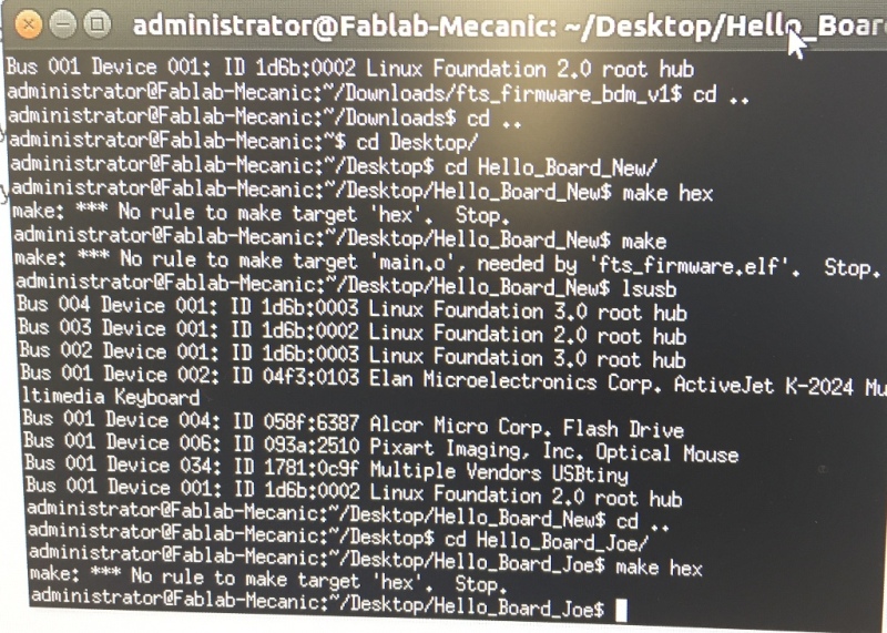
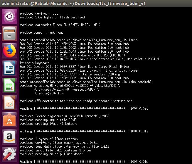
    The g-code used for my ISP:
    Traces,
    Cutout.

    Creative Commons License
    This work is licensed under a Creative Commons Attribution 4.0 International License.