During the eight session dated on March 6 2019, I was introduced to "CNC Computer Controlled Machining"
The group assignment is to test runout, alignment, speeds, feeds, and tool paths for our machine.
The individual assignment is to make something big.
As mentioned in the group assignment, we will test runout, alignment, speeds, feeds, and tool paths for our machine.
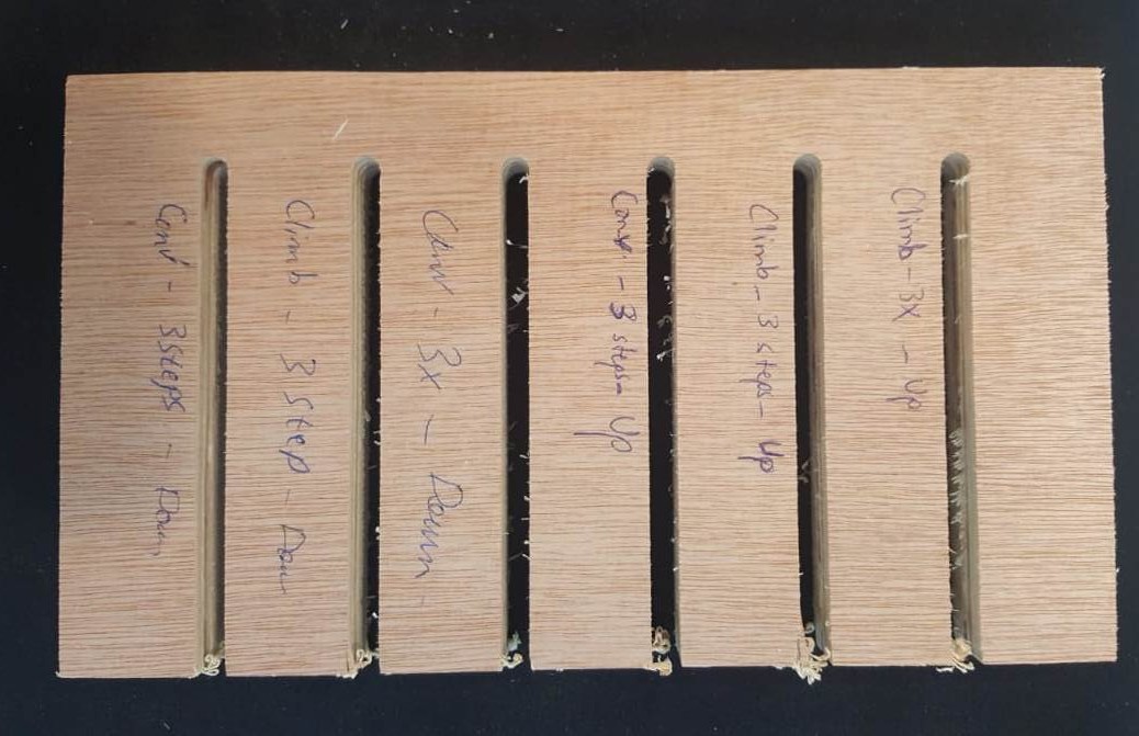
In the first test we used up and down cut milling, tool having 2 flutes, 3 steps and full cut, climb and conventional. The step cuts (up) is cleaner than the full cut.
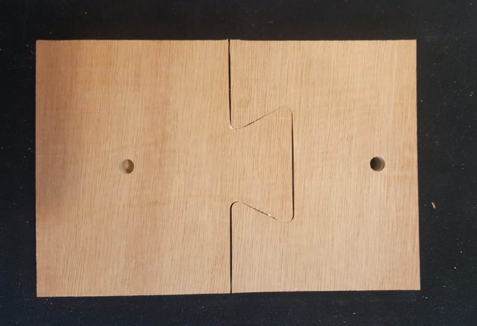
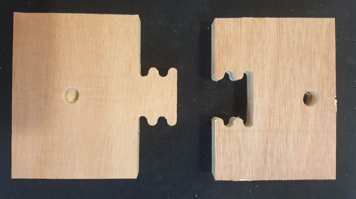
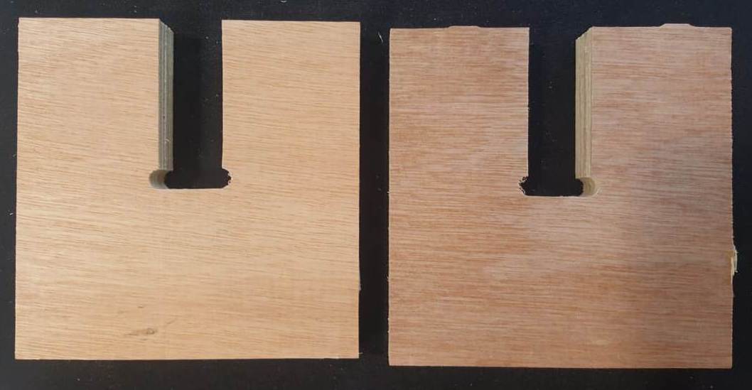
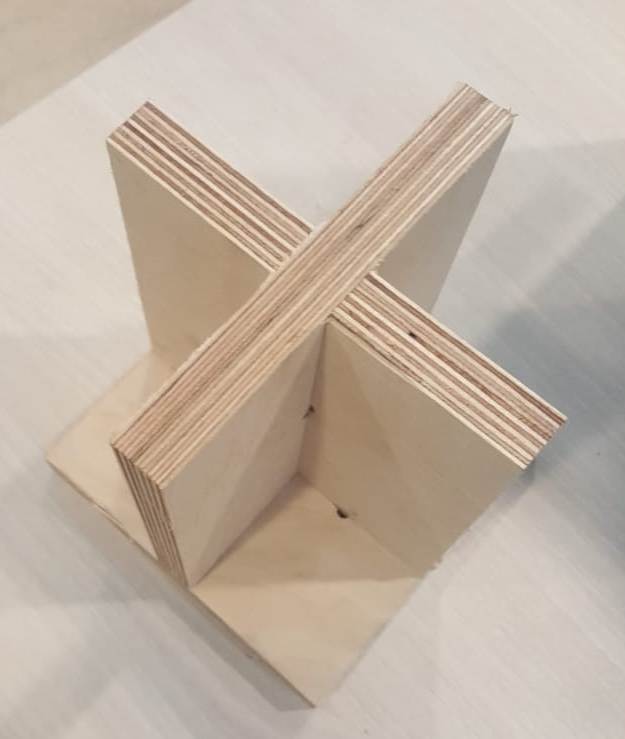
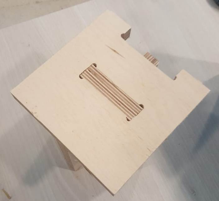
As you can see in the above picture, we tested different types and shapes of joints by using a 18mm plywood test board. We used a "T-bone" End mill having 6mm diameter. The first two ones were easy to fit and strong, in contrary to the last one.
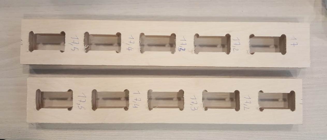
For the last series fit test, we took an average fit for 17.2mm. The reason is that the plywood board thickness was originally 18mm. But after measuring it with a caliper it was 17.7mm. After several test we discovered that 17.2mm is the best scenario. So the cut takes 0.25mm on each side.
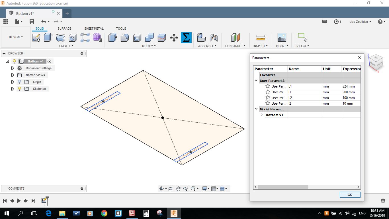
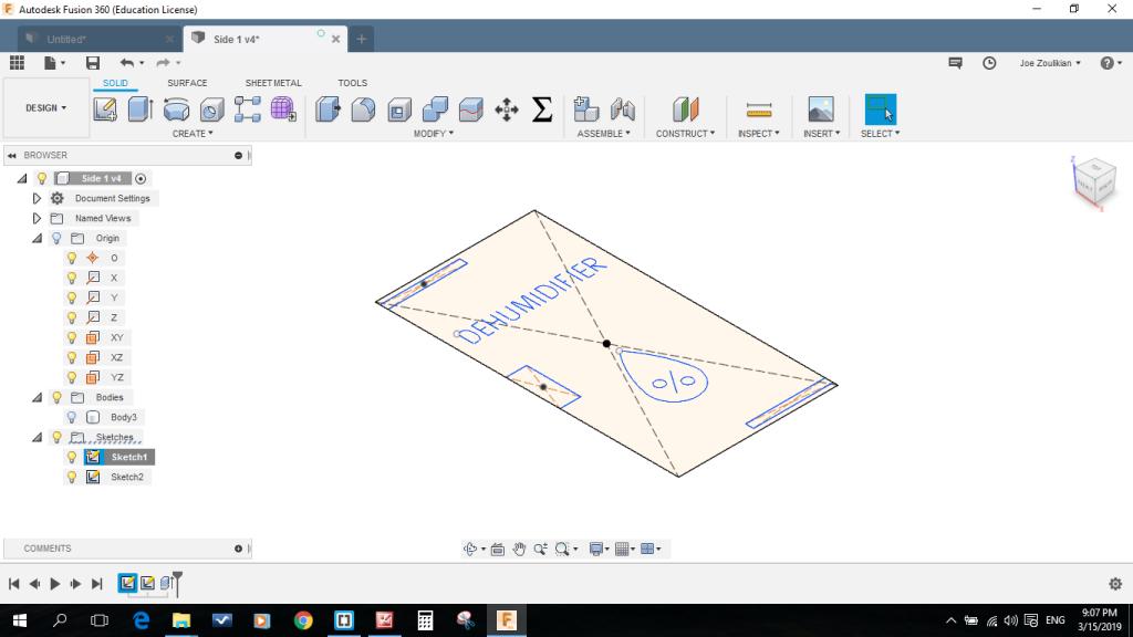
As an individual assignment I decided to manufacture the "Dehumidifier" box by using the mdf type of wood having a thickness of 10mm. For this purpose and after checking the "Ultimaker 3" extended dimensions I started to draw the side wall and the top wall on "Autodesk Fusion 360" always using the parametric option.

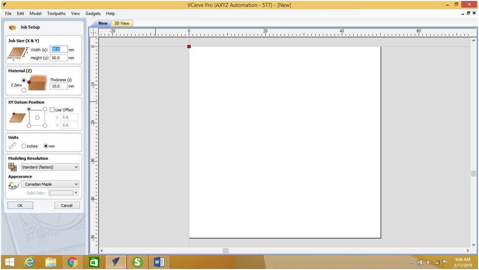
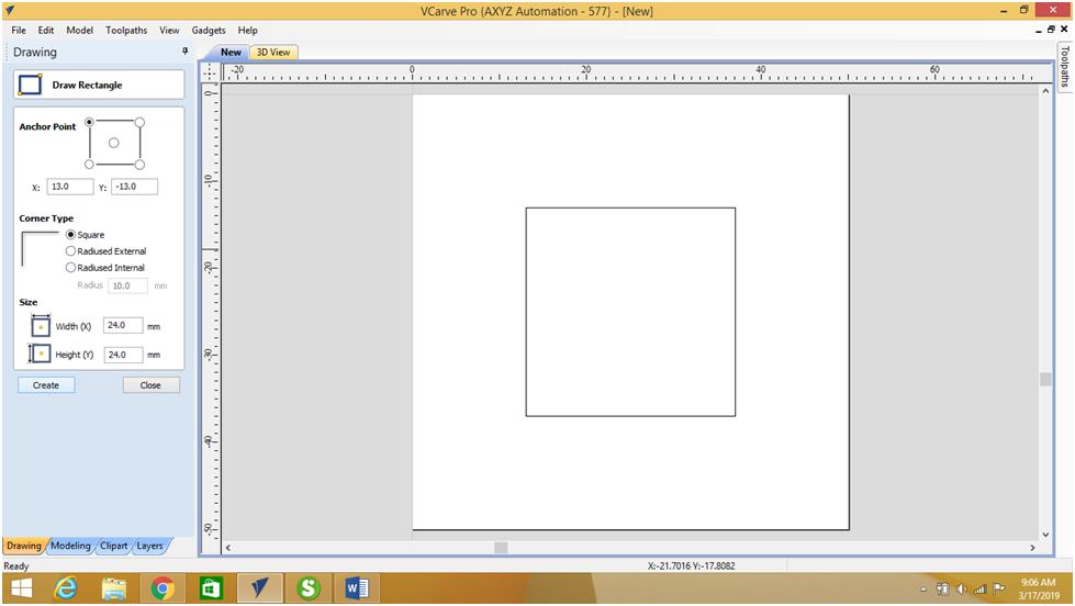
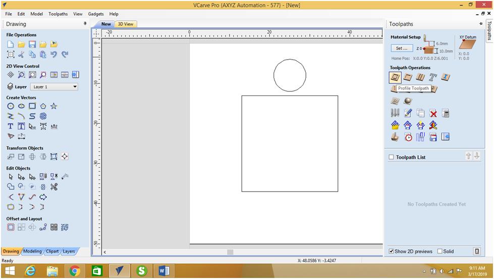
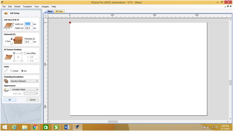
I started practicing the VCarve software by preparing a 50 x 50 mm job working area, then I draw a 24 x 24 mm rectangle, and an 8mm circle.
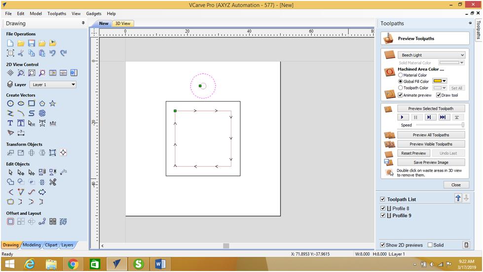
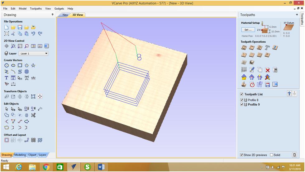
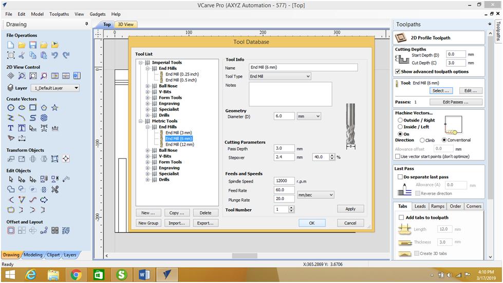
Then I used the Profile Toolpath in the "Toolpath Operation" to start machining, I inserted the depth of cut 10mm, and selected the 6mm Endmill tool, then Inside/Left in the "Machine Vectors", then I selected the outer frame of my rectangle, at the end calculate.
I done the same for the 8mm diameter hole, and I specified the depth of cut to 6mm.
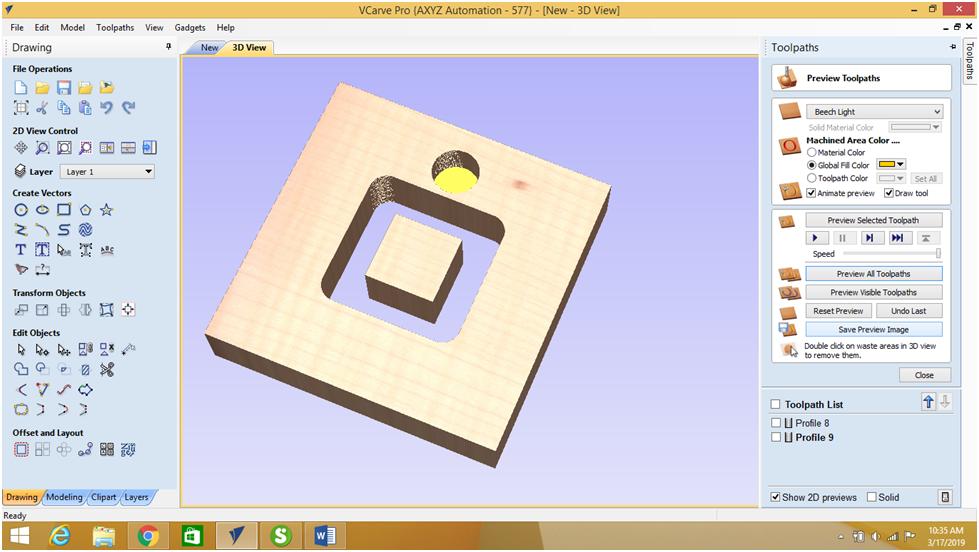
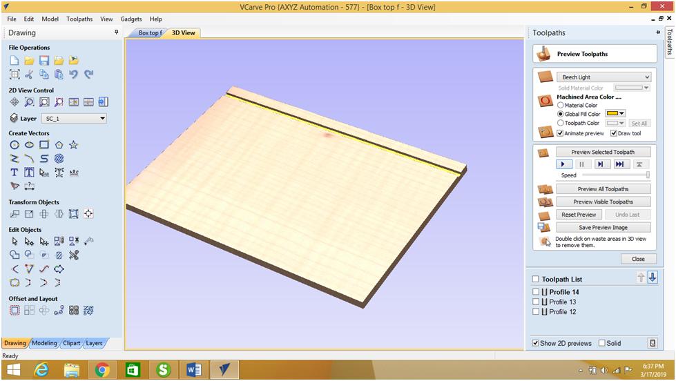
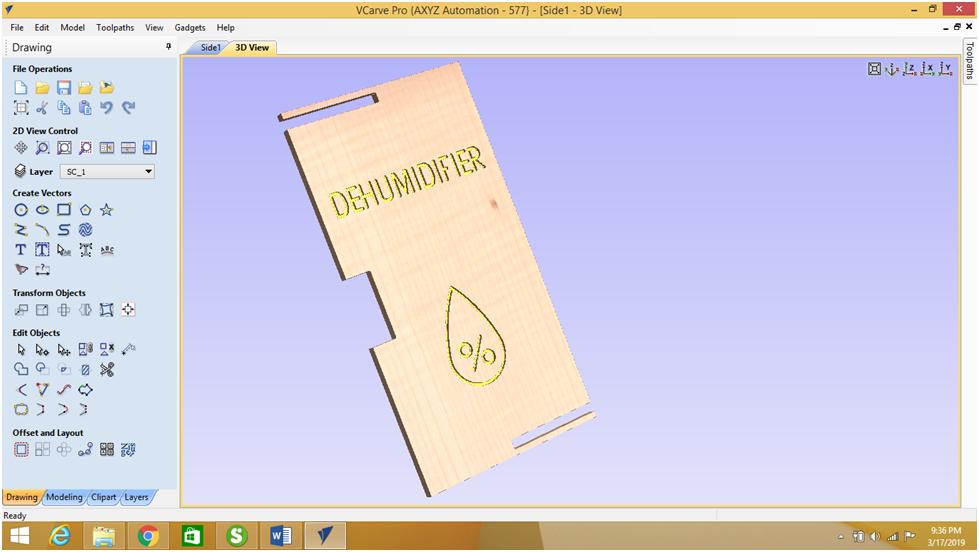
You can see below the 2D and 3D toolpaths, I used the Preview toolpaths to run a simulation of the machining.
After practicing the different options on Vcarve, I started the machining steps of my project in order to generate the G and M Codes.
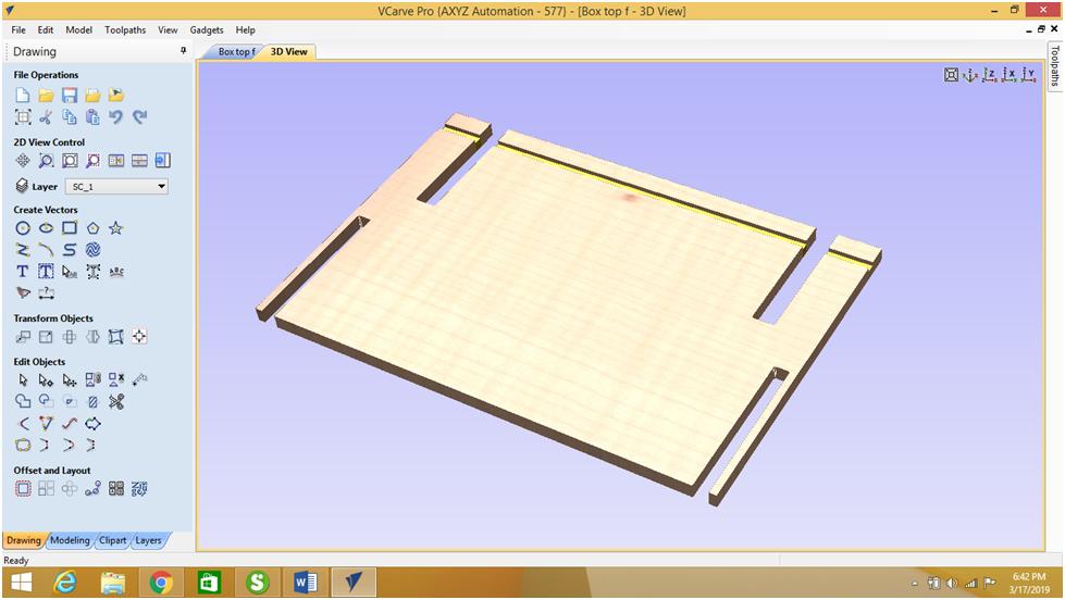
I had saved the previously designed "Fusion files" of the "Dehumidifier" in .dxf format, I started the machining process by opening the Top cover file.
I used a 6mm flat End mill to perform the groove having a depth of cut of 3mm. Then I selected on in "Machine Vectors".
I selected the middle line that is doted as toolpath. To strat the machining I pressed on calculate.
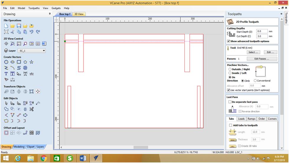
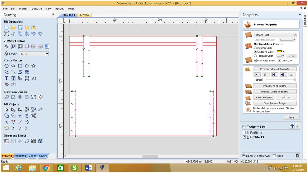
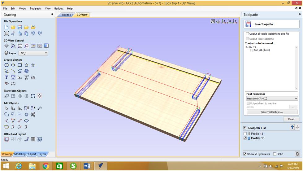
In order to generate the GM Codes related to the 6mm groove, I used "Save Toolpaths function", same thing was done for the 3mm grooves.
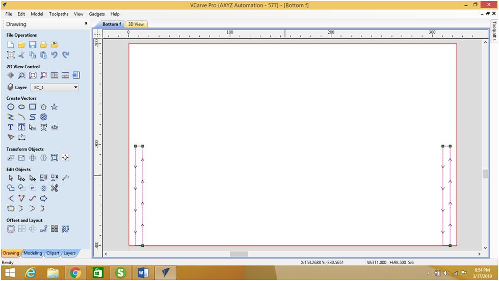
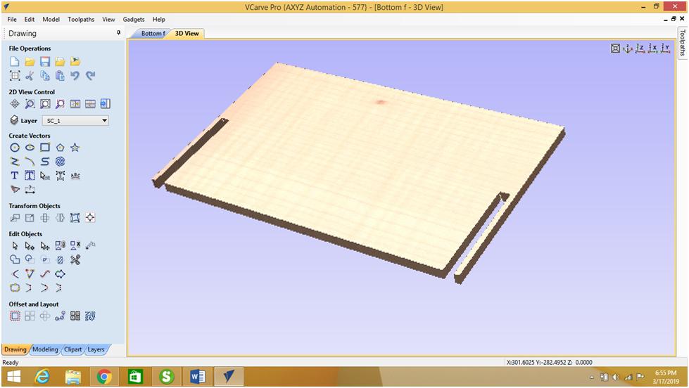
I performed the same steps for the bottom plate.
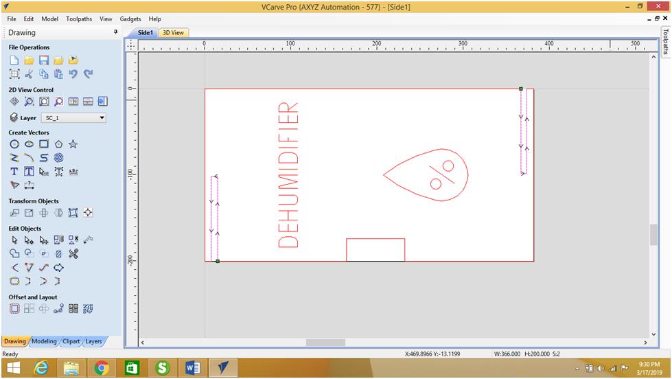
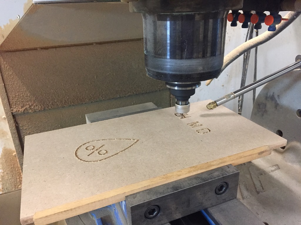
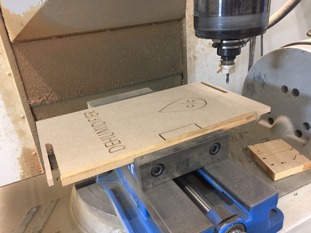
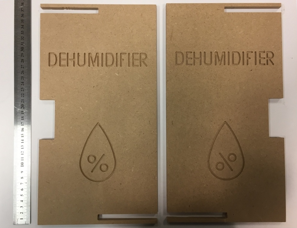
For the Side 1 plate, I started by selecting the text, then the logo, using a 3mm flat end mill carbide tool and having a 3mm depth.
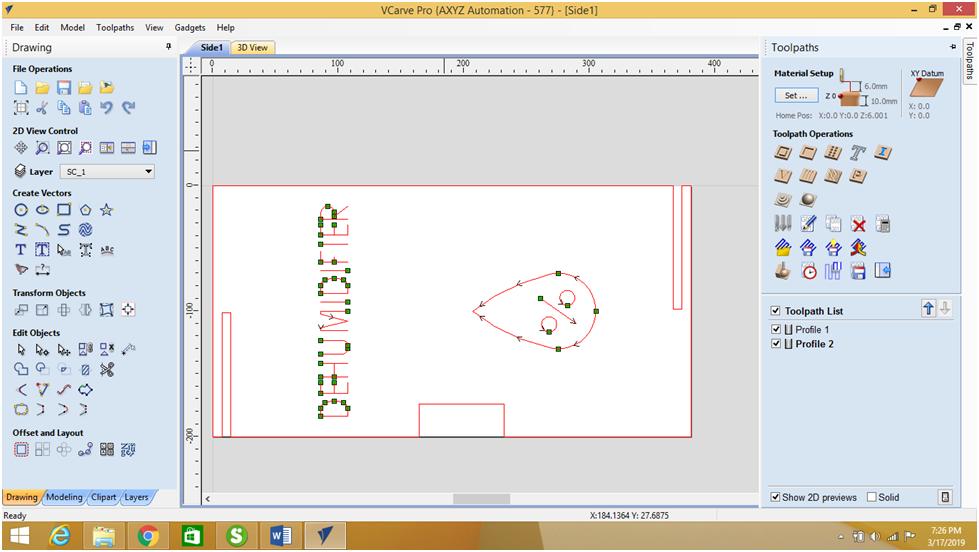
Then I selected the two long grooves. As for the side rectangle I used the Inside/Left in "Machine Vectors".

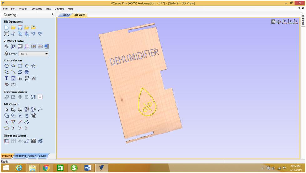
I have done the same process for the side 2 plate:

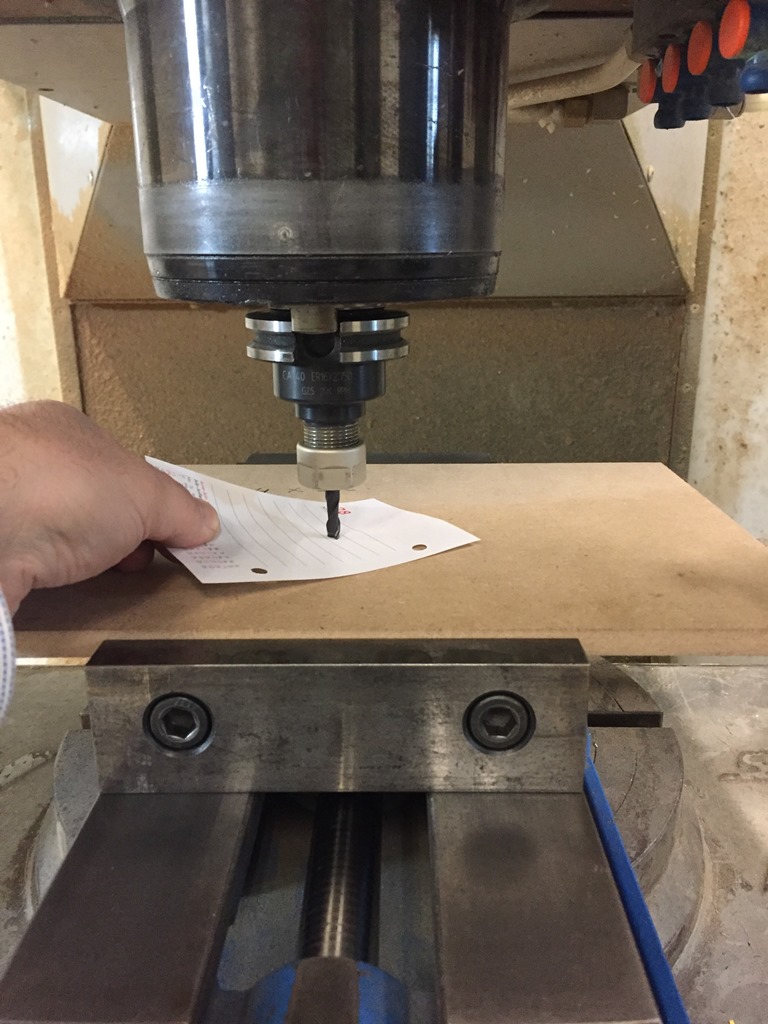
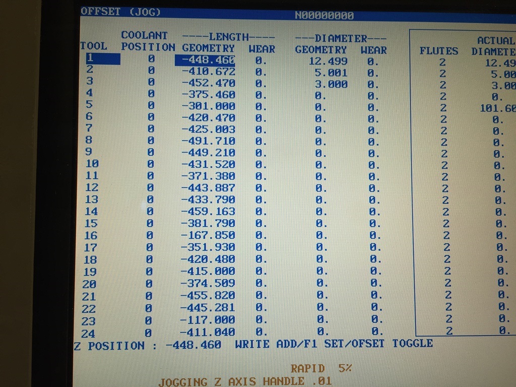
I started by locating the X and Y zero offset, I used the G154 P8. Then I located the T1 Z zero offset by using the paper technic.
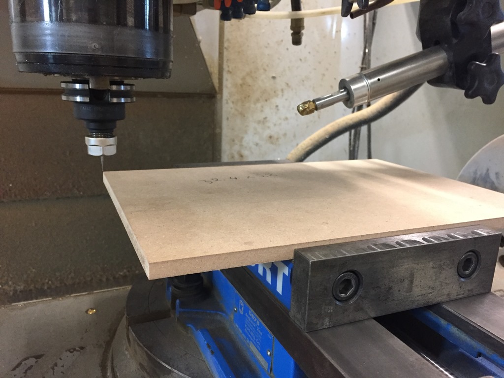

After sending the G M codes to the HAAS VF-6 Milling machine through a serial connection, I started the machining process by using the Air collant.

.JPG)
.JPG)
.JPG)
.JPG)
.JPG)
Since I need to do grooves for the PLA and PVA tubes, and since the sides should be attached to the top plate I used these types of joints. But for the final one in acrylic I will use the T-slots type of joints.
The bottom design in Fusion 360,
The top cover in Fusion 360,
The side wall in Fusion 360,
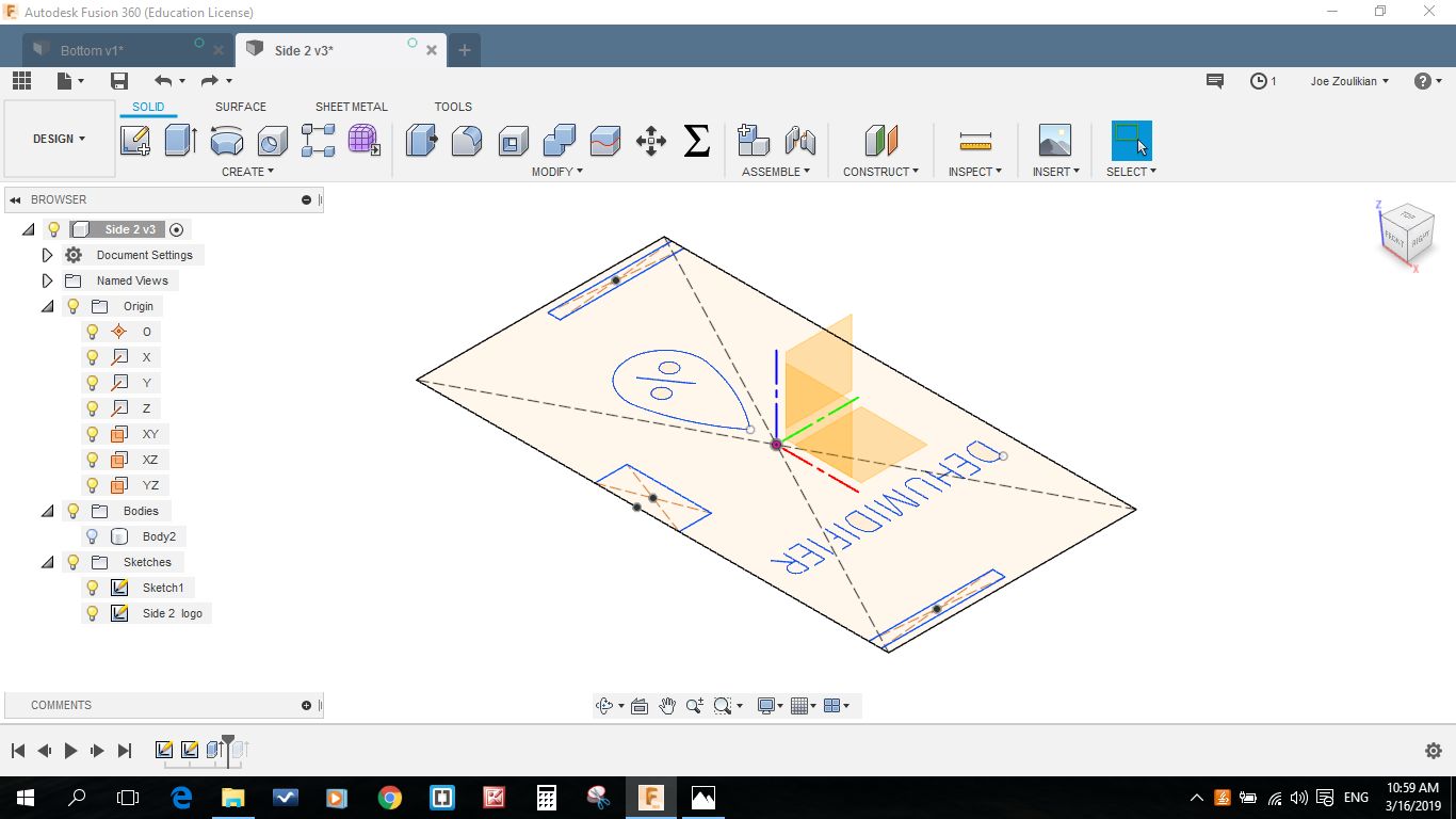
The other side wall in Fusion 360,
The bottom design in dxf format,
The Top design in dxf format,
The Side 1 in dxf format,
The Side 2 in dxf format,
The Top plate G and M codes using a 6mm End mill,
The Top plate G and M codes using a 3mm End mill,
The Side 1 plate G and M codes using a 3mm End mill,
The Side 2 plate G and M codes using a 3mm End mill,
The Bottom plate G and M codes using a 3mm End mill,

This work is licensed under a Creative Commons Attribution 4.0 International License.