During the nine session dated March 13 2019, I was introduced to "Embedded Programming".
The individual assignment is to read a microcontroller data sheet, program my board to do something, with as many different programming languages and programming environments as possible.
The group assignment is to compare the performance and development workflows for other architectures.
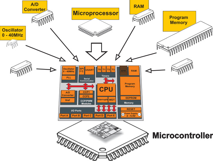
In today's digital world everything is based on microprocessors and microcontrollers. So we have to know about the microprocessors and the microcontrollers.
Microcontrollers usually must have low-power requirements since many devices they control are battery-operated. Microcontrollers are used in many consumer electronics, car engines, computer peripherals and test or measurement equipment. And these are well suited for long lasting battery applications. The dominant part of microcontrollers being used now a days are implanted in other apparatus.
The microcontrollers are characterized regarding bus-width, instruction set, and memory structure. For the same family, there may be different forms with different sources.
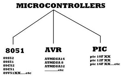
The types of microcontroller is shown in figure above, they are characterized by their bits, memory architecture, memory/devices and instruction set. Let’s discuss briefly about it.
The bits in microcontroller are 8-bits, 16-bits and 32-bits microcontroller.
Reference: Microcontrollers types and applications
A Microprocessor is a digital integrated circuit which is used in general computer and having the millions of transistors, resistors and other electronic components incorporate in as single small IC. The microprocessor works as CPU (central processing unit) of the computer.
The microprocessor is designed to support a set of multiple peripheral like USB ports, video ports, audio ports, network interfaces like Ethernet, WI-Fi, Bluetooth, additional memory interfaces like CD/DVD ROM, magnetic disc drives and SD/MMC external interfaces.
The microprocessor chip will work with the integration of memory devices, input and output peripherals only. The first commercial microprocessor is Intel 4004 which is designed by the Intel Corporation in 1971. This is a 4-bit microprocessor available in 16-pin duel in-line package. The successor versions of microprocessors are Intel 4040, 8008, 8085, 8086, etc. Generally microprocessors are used in personal computer systems.
Reference: Microprocessor
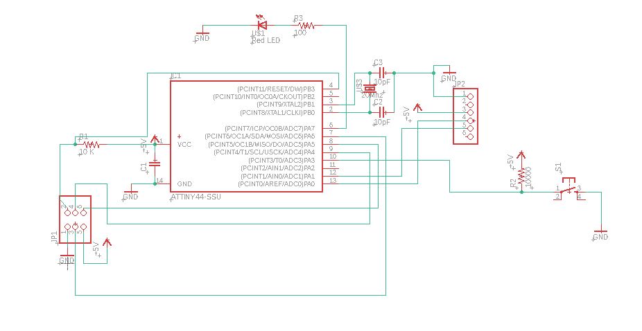
In this assignments I will be focusing on programming the "ATtiny44" AVR Microcontroller used on the "Hello Board" in Week 7's assignment "Electronic Design".
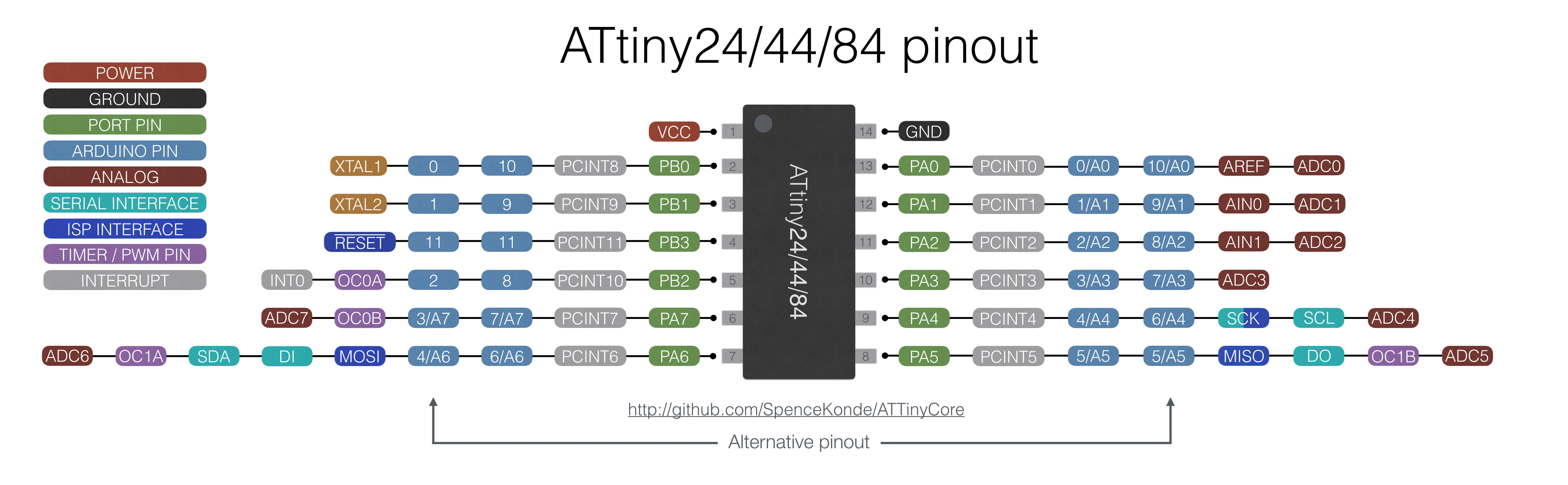
The Atmel "ATtiny24/44/84" is a low-power CMOS 8-bit microcontroller based on the AVR enhanced RISC architecture. By executing powerful instructions in a single clock cycle, the Atmel "ATtiny24/44/84" achieves throughputs approaching 1MIPS per MHz allowing the system designed to optimize power consumption versus processing speed.
Pin Configuration:
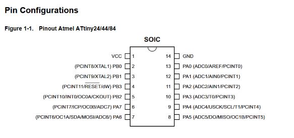
Pin Descriptions:
My Hello Board designed previously in Week 7:
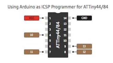
Below is the process showing how to use an Arduino Uno as an In-System Programmer or ISP. An ISP allows AVR microcontrollers to be programmed and reprogrammed without having to remove them from the circuit. Six wires are needed to program any AVR microcontroller.
Three of these wires are referred to as the Serial Peripheral Interface (SPI) and are the Master In Slave Out (MISO), Master Out Slave In (MOSI), and Serial Clock (SCK).
The "Master" is the ISP or the device you are using to program the AVR chip. The "Slave" is the AVR chip being programmed. The other three wires are for the 5V power supply (VCC), Ground (GND), and Reset (RESET).
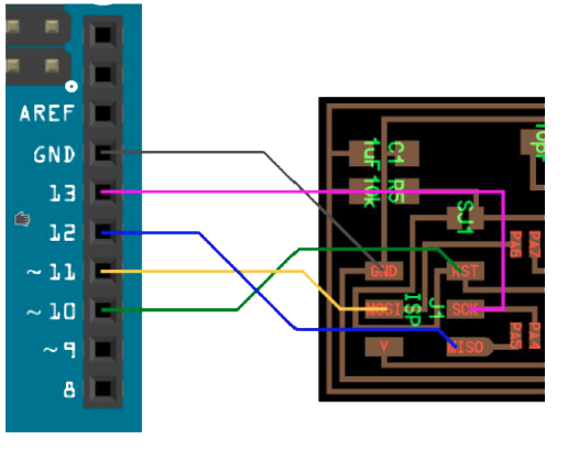
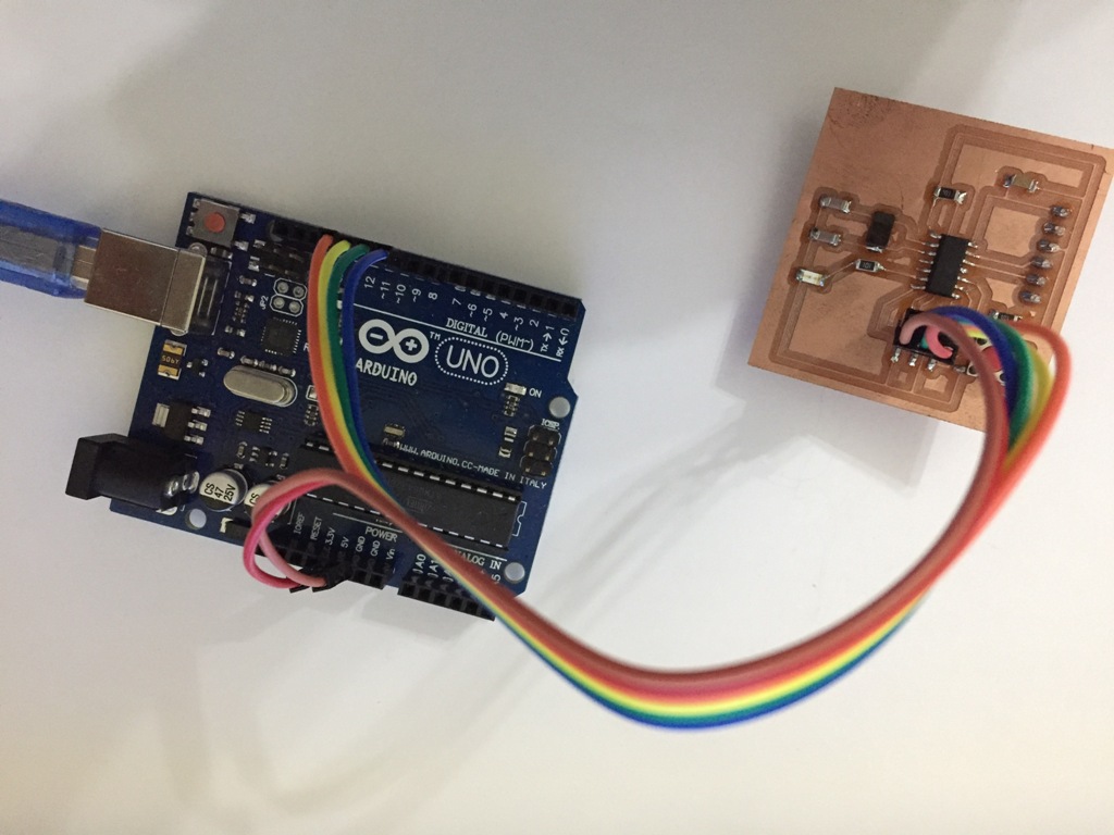
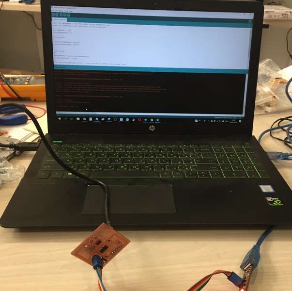
The wiring:
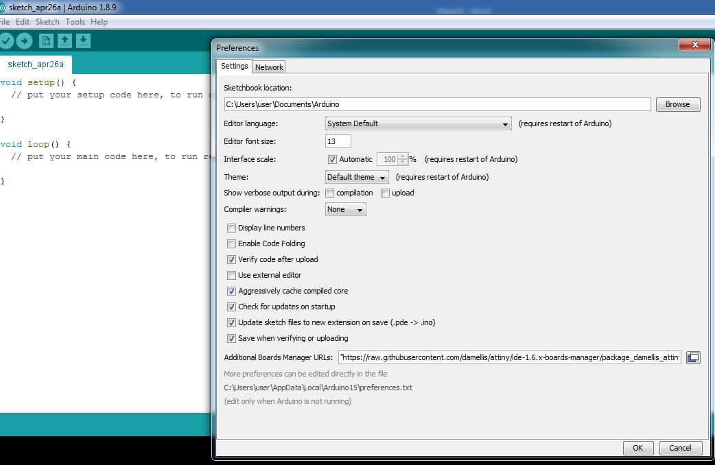
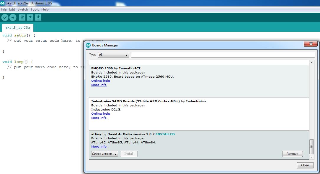
I installed Attiny44 board on the Arduino IDE. To do that I go to settings and insert this link: "https://raw.githubusercontent.com/damellis/attiny/ide-1.6.x-boards-manager/package_damellis_attiny_index.json".
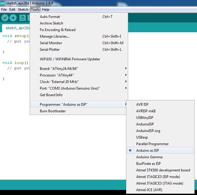
As you can see in the below picture, in tools I set the Processor to "ATtiny44" and the Clock to "External 20 MHz" to commend my hello board.
Then set the programmer "Arduino as ISP".
At the end I must burn bootloader for the first time I am programing my hello board or when I want to reset it.
I will program the red led to turn on when I press the reset push button, and to blink the red led when I keep pressing the push button.
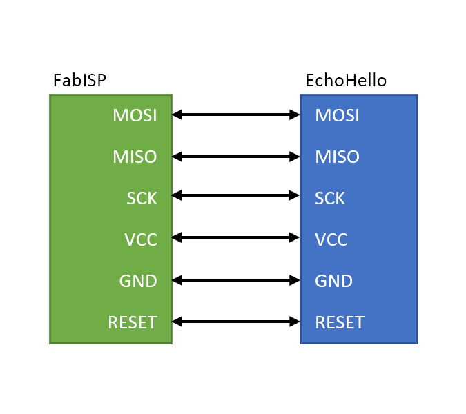
The connection between my "FabISP" and my "Hello Board" will be as follows: each Pin on a board is connected to it's similar on the other board.
According to the ATtiny 44 pinout configuration my wiring will be as follow:
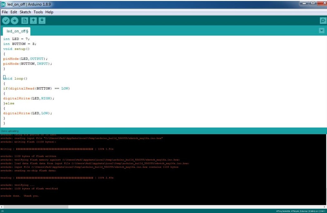
The simple LED On/Off
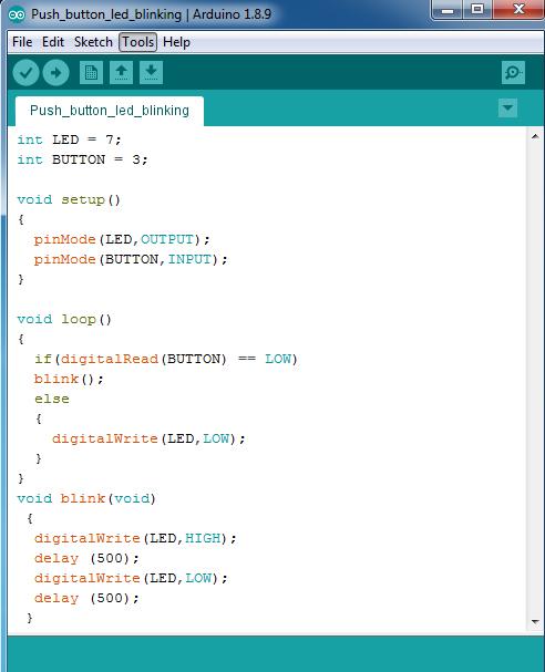
The blinking LED
Registers are the only way of interaction for a microprocessor.
I will write the program, that turns LED On and Off via push button.
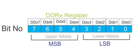
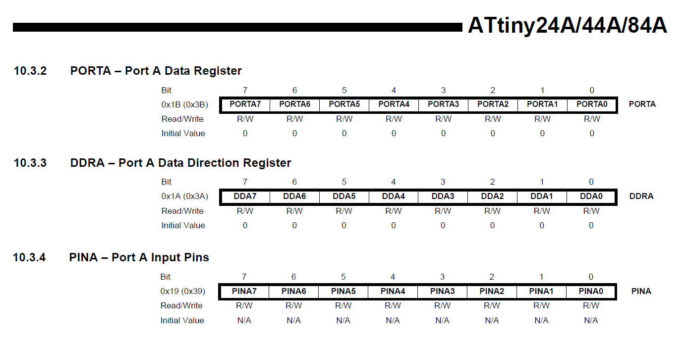
To make all pins of port A as input pins: DDRA = 0b00000000;
To make all pins of port A as ouput pins: DDRA = 0b11111111;
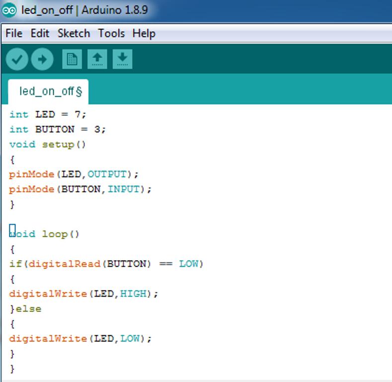
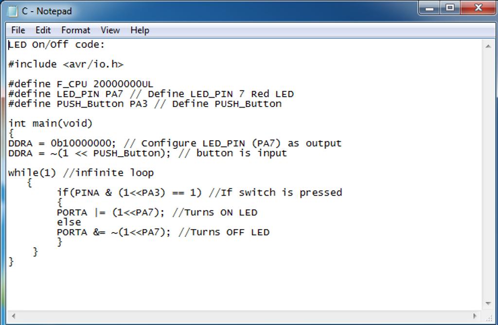
The Code to turn On/Off a LED.
Arduino Code for simple Push Button
Arduino Code to blink the LED,
C Code

This work is licensed under a Creative Commons Attribution 4.0 International License.