During the fourteen session dated on April 24 2019, I was introduced to "Networking and Communications."
The individual assignment is to design, build, and connect wired or wireless node(s) with network or bus addresses.
The group assignment is to send a message between two projects.
Types of Communications:
Serial Communication:
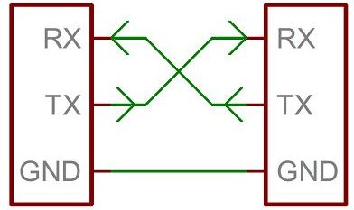
Serial communication is the process of sending data one bit at a time, sequentially, over a communication channel or computer bus. This is in contrast to parallel communication, where several bits are sent as a whole, on a link with several parallel channels. We should always share the ground Pins between the MCUs.
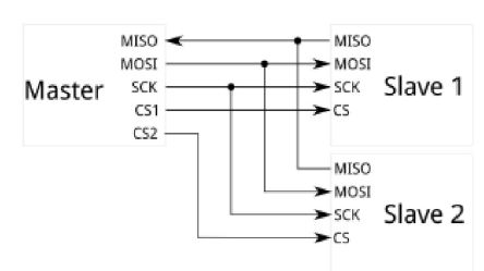
The Serial Peripheral Interface SPI bus is a synchronous master-salve serial communication interface used for short distance communication, primarily in embedded systems.
With an SPI connection there is always one master device (usually a microcontroller) which controls the peripheral devices. We should always share the ground Pins between the MCUs. Typically there are three lines common to all the devices:
MISO (Master In Slave Out) - The Slave line for sending data to the master,
MOSI (Master Out Slave In) - The Master line for sending data to the peripherals,
SCK (Serial Clock) - The clock pulses which synchronize data transmission generated by the master and one line specific for every device:
SS (Slave Select) - the pin on each device that the master can use to enable and disable specific devices.
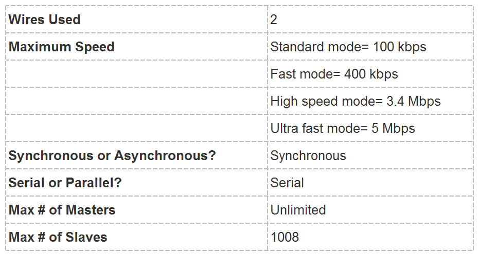
I2C:
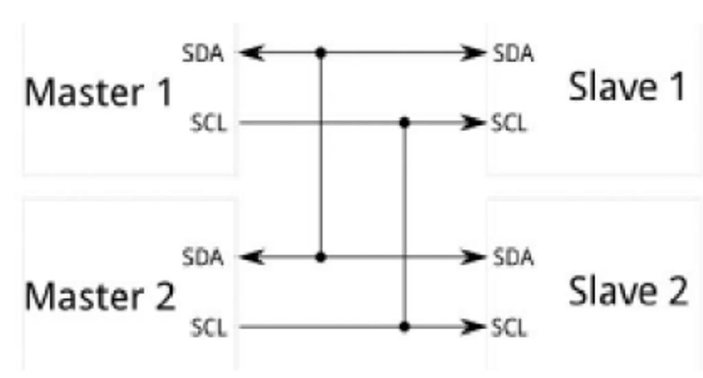
I2C its pronounced I-Squared-C: is a multi-master, multi-slave, serial computer bus developed originally by Philips and is used to connecting between processors and smart devices. This is really useful when we want to have more than one microcontroller logging data to a single memory card or displaying text to a single LCD.
SDA (Serial Data): The line for the master and slave to send and receive data.
SCL (Serial Clock): The line that carries the clock signal.
I2C is a serial communication protocol, so data is transferred bit by bit along a single wire (the SDA line).
Like SPI, I2C is synchronous, so the output of bits is synchronized to the sampling of bits by a clock signal shared between the master and the slave. The clock signal is always controlled by the master. We should always share the ground Pins between the MCUs.
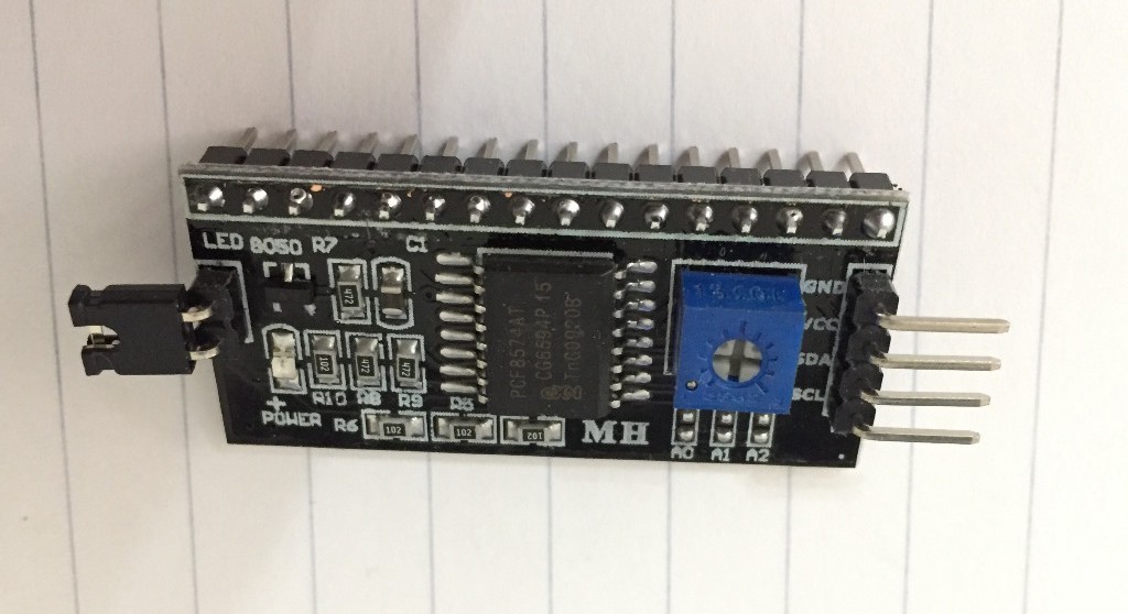
I already had used it in the output device week connected to LCD to minimize the connections according to the below wiring.
Individual Assignment: design, build, and connect wired or wireless node(s) with network or bus addresses.:
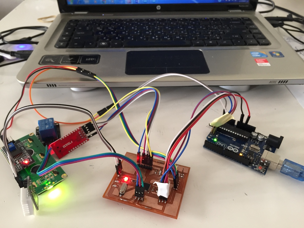
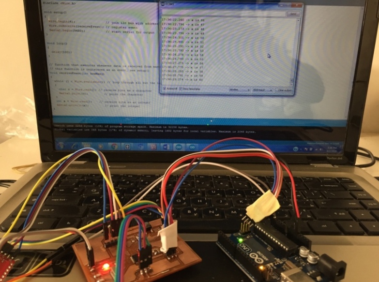
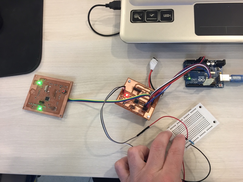
In the wired category: I decided to connect my PCB done during the "Input/Output Devices" week as master and use the Arduino as slave using the I2C protocol.
I used the below wiring:
GND pin of my PCB to GND pin of Arduino,
SDA pin of my PCB to A4 pin of Arduino,
SCL pin of my PCB to A5 pin of Arduino.
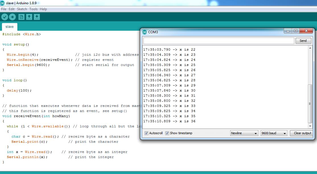
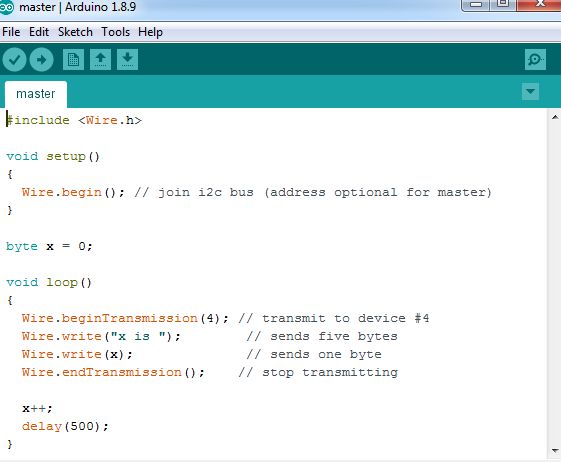
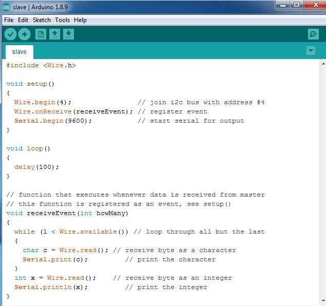
The Master and Slave codes:
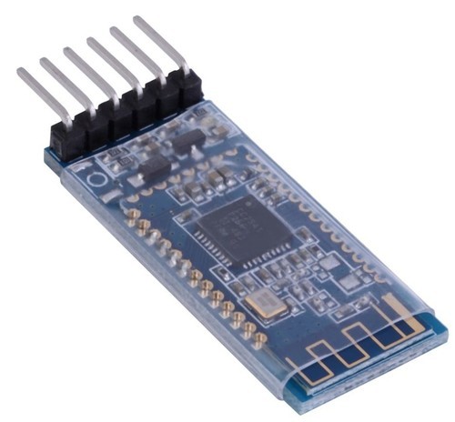
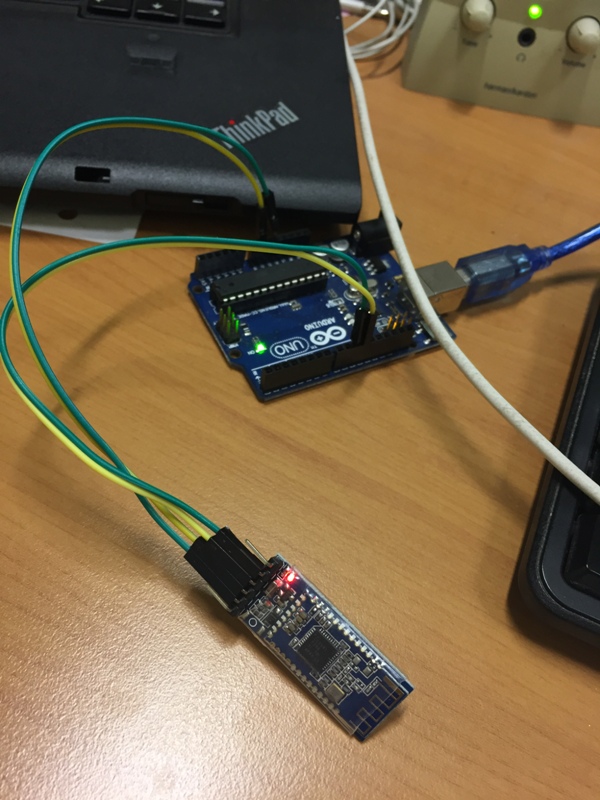
In the wireless category: I decided to use the Bluetooth module to connect my PCB to my desktop. Because it will be useful for my final project to have a wireless connection between my Dehumidifier and my desktop, where I will develop an application that will display the humidity level and the status of my Dehumidifier.
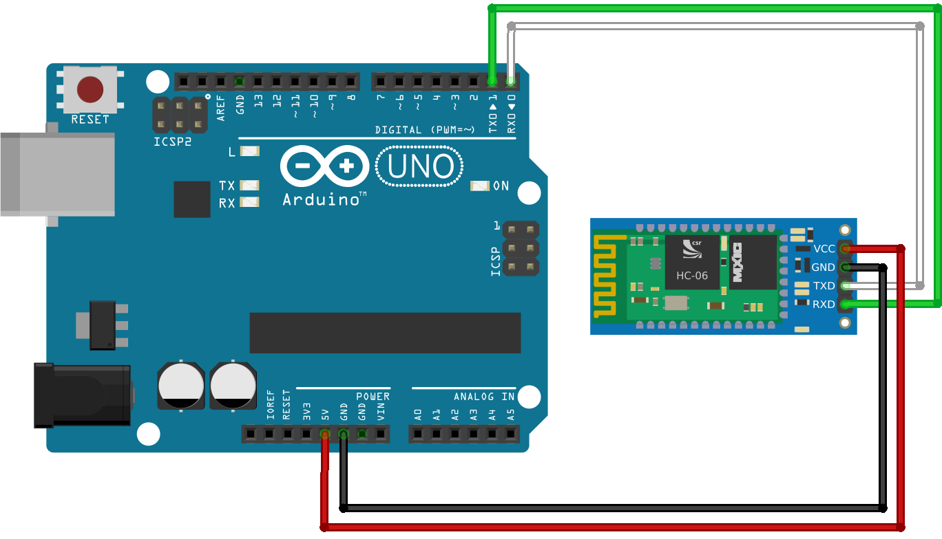
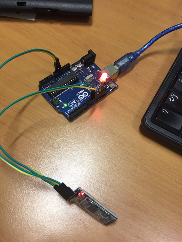
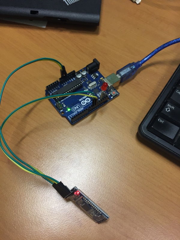
I will use the HM-10 Bluetooth device with following wiring:
Arduino TX to HM-10 RX,
Arduino RX to HM-10 TX,
Arduino GND to HM-10 GND,
Arduino 5v to HM-10 +5v.
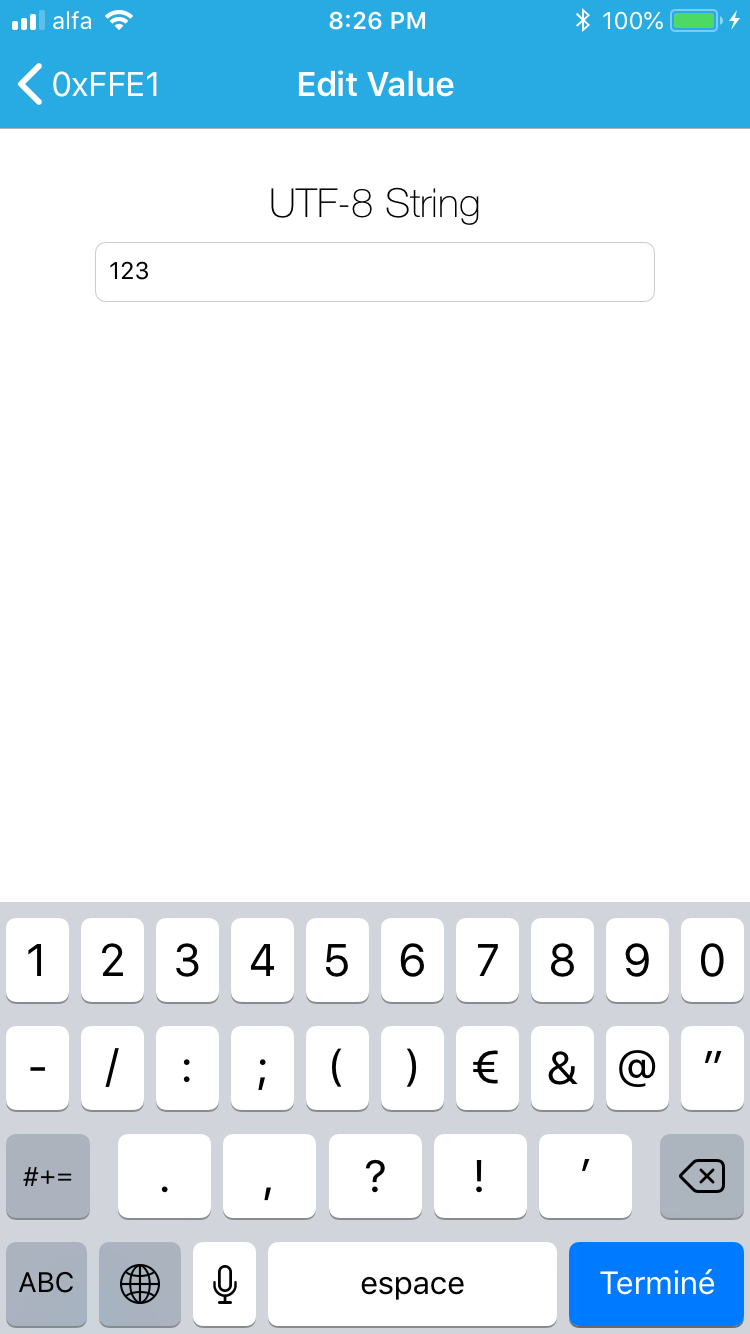
I installed the "LightBlue" application on my Iphone.
Then established a connection between the Iphone and the Arduino via HM-10, the LED on the module of HM-10 stop blinking.
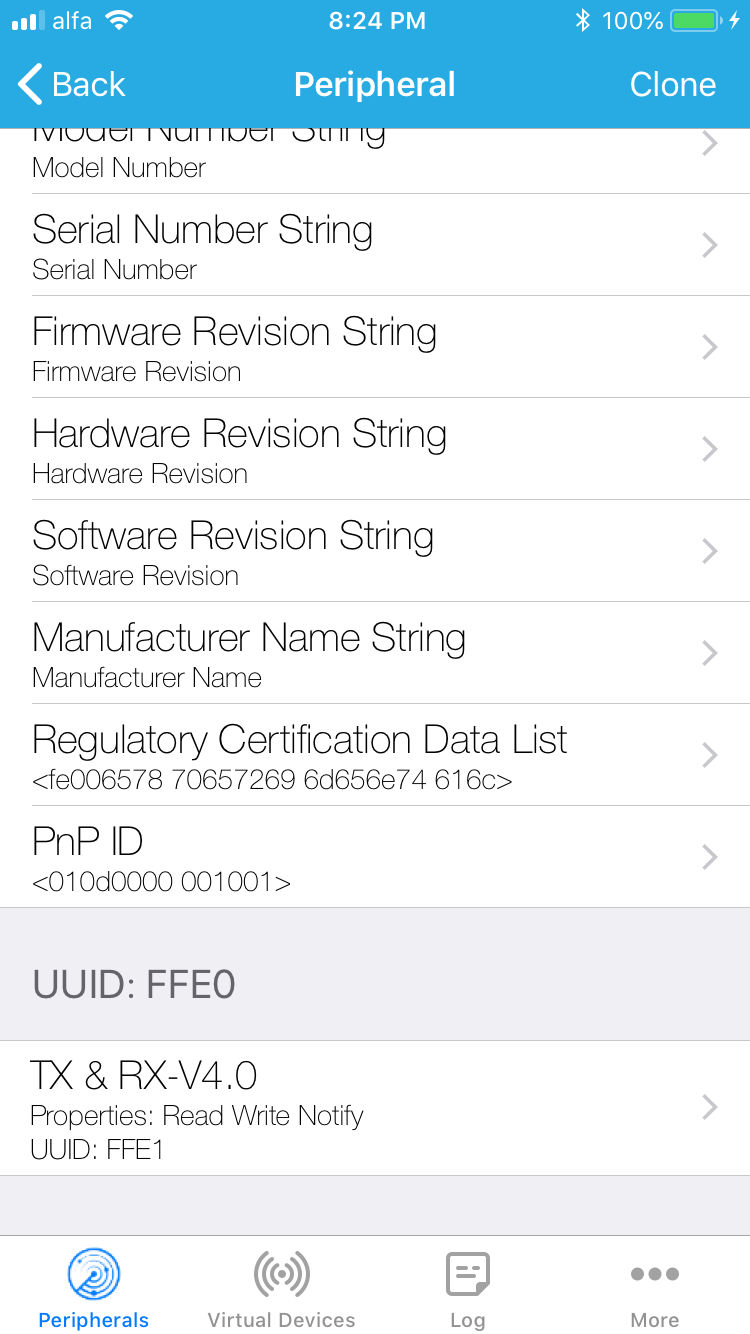
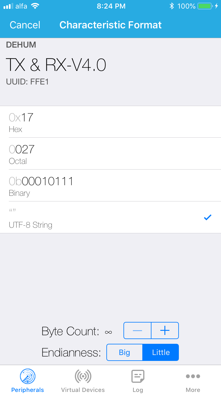
I selected TxRx, then changed the "Hex" to "String".
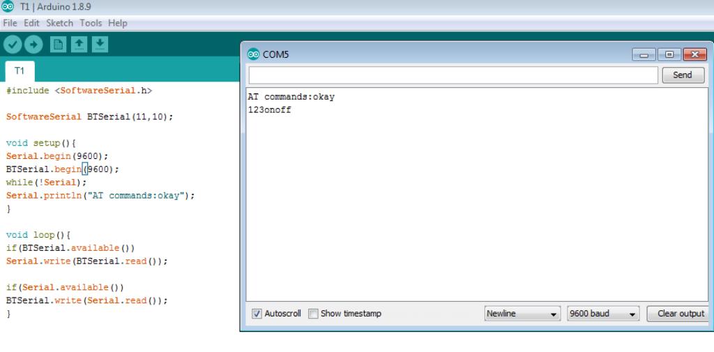
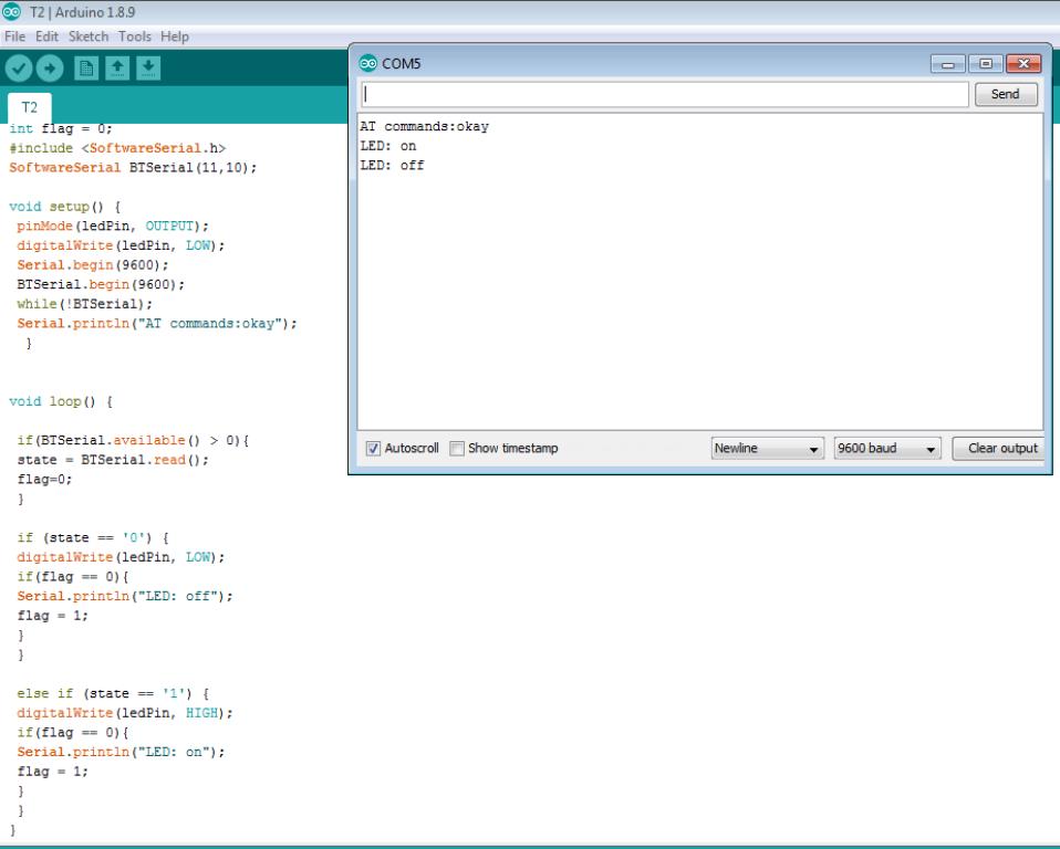
Then I tried a simple communication between my phone and the laptop.
I added a Red LED on Pin13 and turn it On by sending 1.
I turned the LED Off by sending 0.
Group Assignment:
The group assignment is to send a message between two projects.
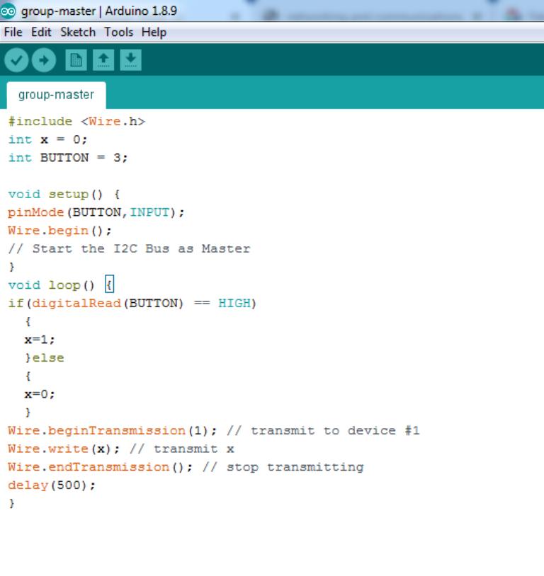
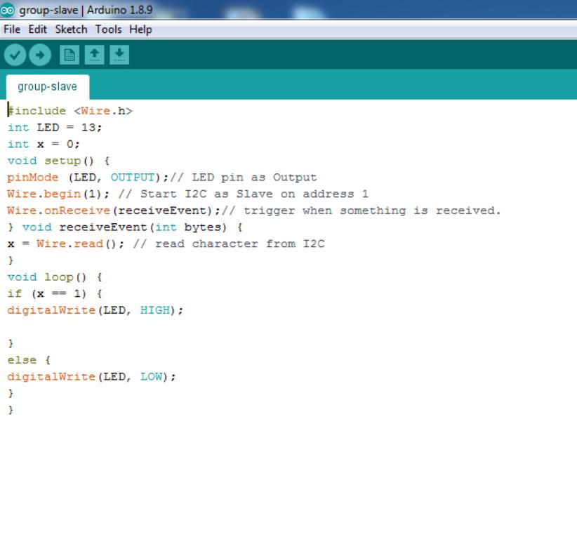
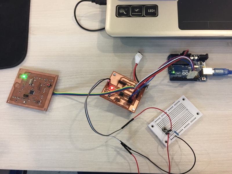
We decided to use my PCB as a "Master" and the one of Nagy as a "Slave".
We added a push button to my PCB and used the LED on the PCB of Nagy.
We connected the boards through I2C connection. (SDA to SDA, SCL to SCL)
The Arduino Codes for the "Master" and the "Slave":