During the seven session dated on Wednesday February 27 2019, I learned how to design a Printed Circuit Board "PCB", and how to test the operations of a Microcontroller.
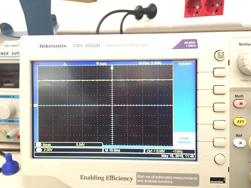
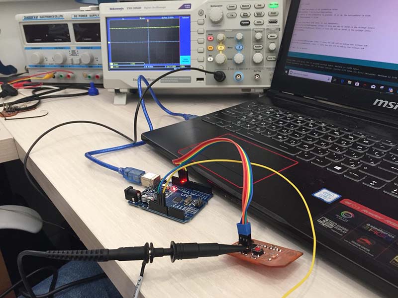
The group assignment is to use the test equipment in our lab to observe the operation of a microcontroller circuit board.
The individual project is to:
Redraw the echo hello-world board, by adding a button and a LED.
Check the design rules, make it, and test it.
The new board functionality:
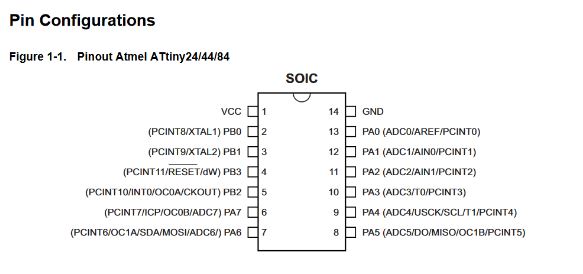
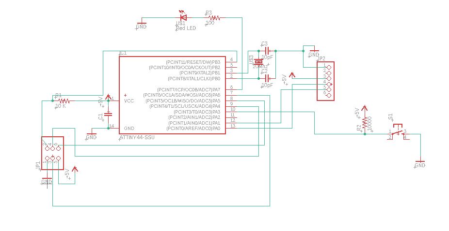
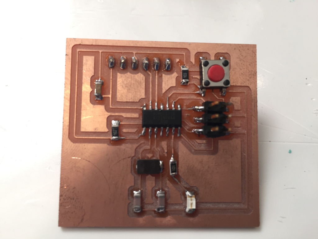
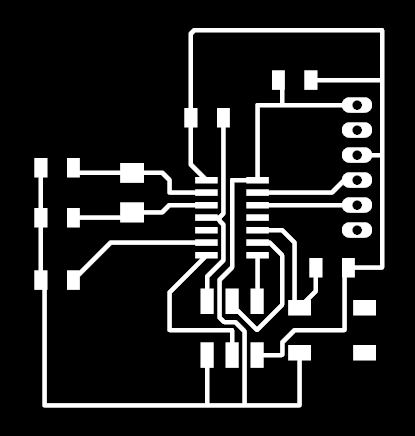
Based on the original "hello-world" board shown below, I designed the new "hello-world" board by adding a Red LED and a push button. I connected the Red LED to the output pin 6 (PA7) and the push button to the input pin 10 (PA3) so that whenever we press the reset push button, the Red LED will turn On.
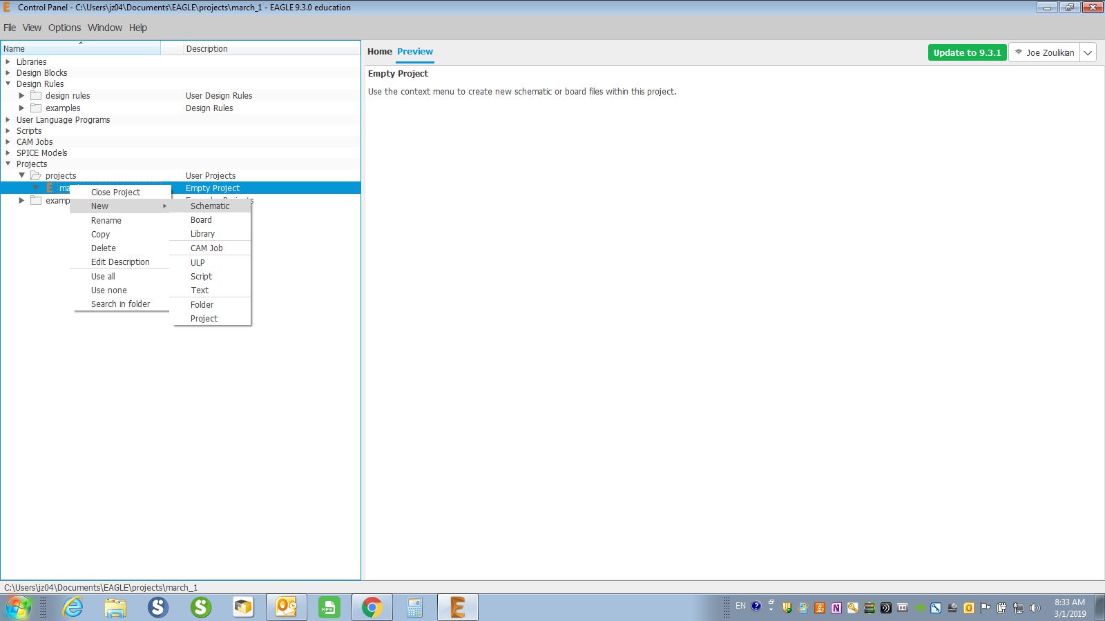
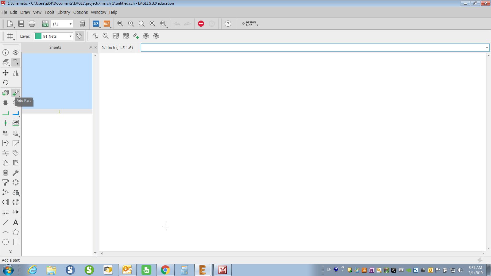
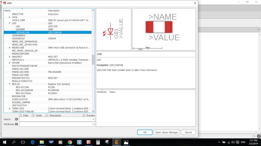
First of all, I opened a new file then inserted the fablab academy library in it and started to add components: like resistors, capacitors, etc...
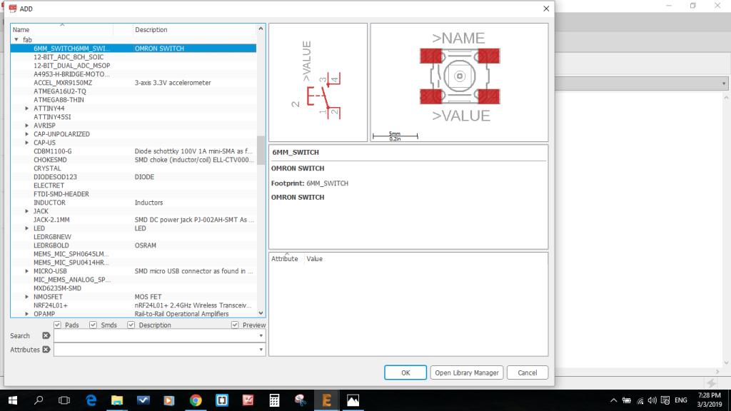
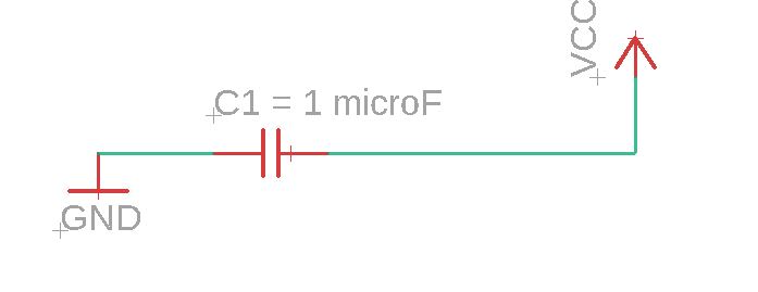
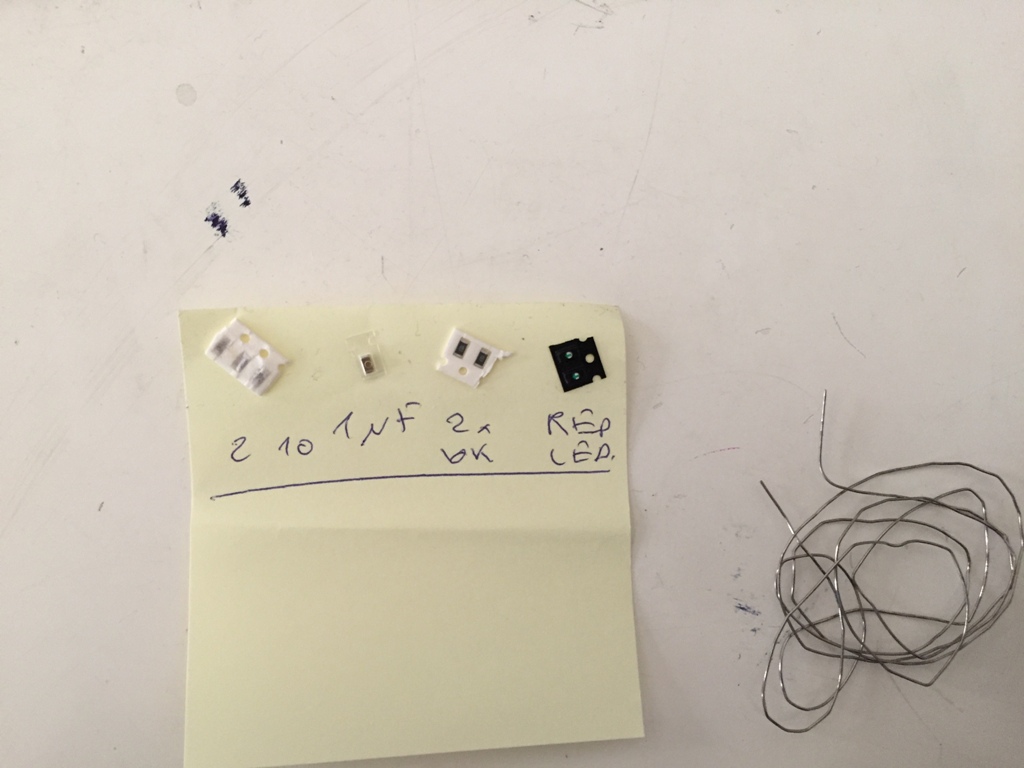
We should always connect a capacitor of 1 microF in parallel to the power supply. According to the Red LED specifications, I must use a Resistor in series having a value of = (5V - 2.4V)/0.03 A = 86.6 Ohm, so I will use the available 100 Ohm resistor. I checked the Red LED polarity and I solder it accordingly.

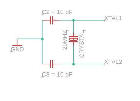
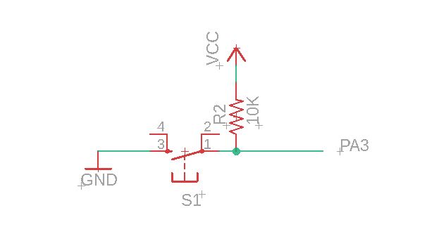
For the case of the 20 MHz Crystal as per the requirements of its data sheet we must have two capacitors of 10 picoF(to replace the 8picoF) in parallel to it and connected to the ground from their middle connecting point. For the push button we must have the standard 10KOhms resistor in series with it.
During designing my Schematic, I used rotate, move, cut, value, name, label, Net, and many others functions to have the final below schematic.
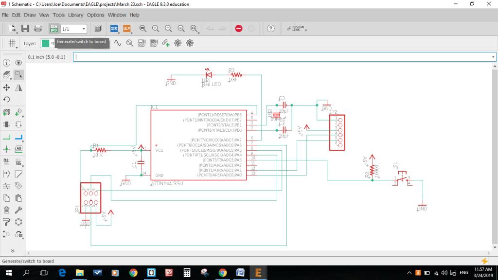
I used the function "Switch to board" to have the draft layout of the PCB.

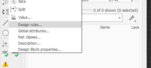
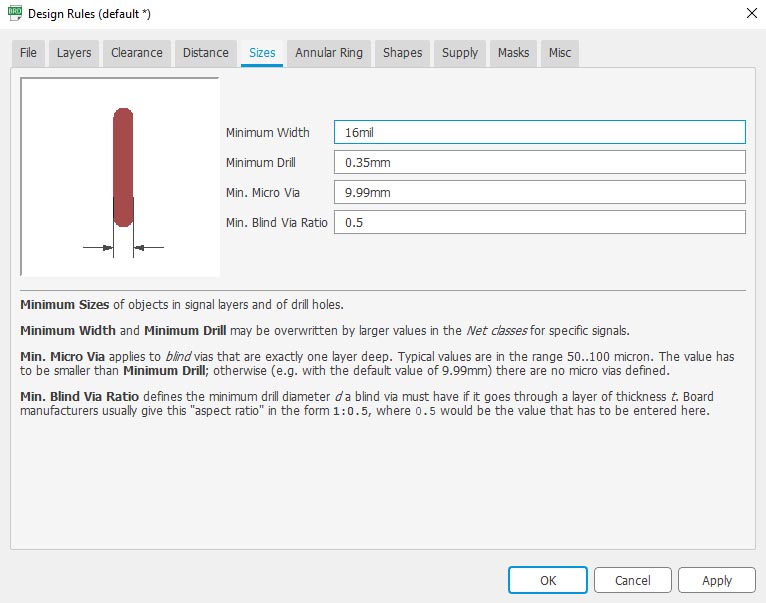
Then I adjusted the design rules before routing. For that purpose, I openned "Design rules" from the toolbar, Edit, Design rules:
I adjusted the Clearance to 16mil:
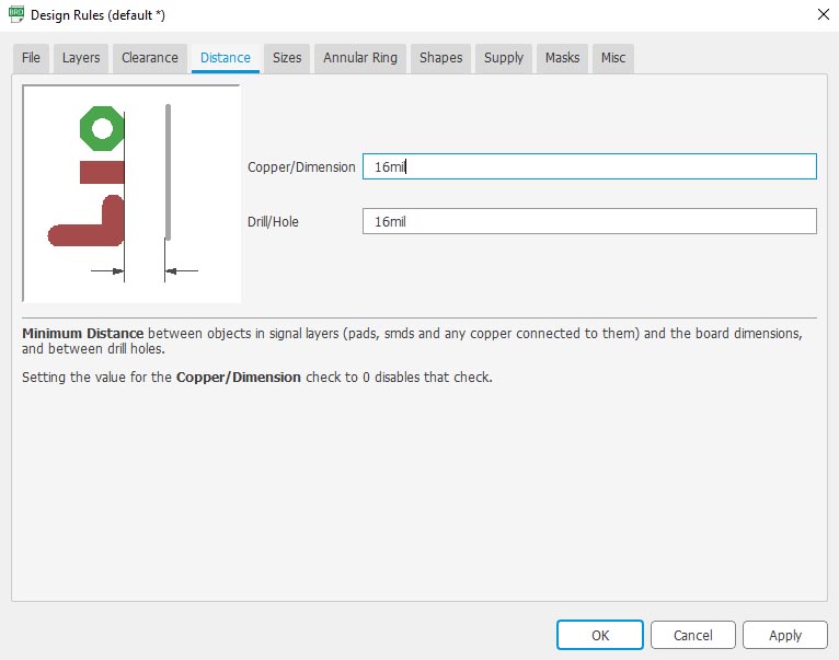
I adjusted the Distance to 16mil:
I adjusted the Size to 16mil:
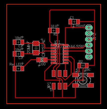
I used rotate, move, value, name, label, and specifically route and many other functions to reconnect, finalize and simplify the connections and have the below final layout. I also checked and repaired the errors by using tools/errors function.
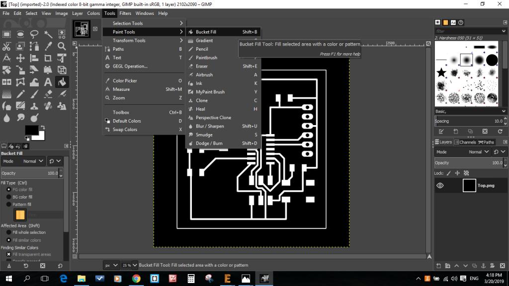


Then i used the "fab modules" online Software to create the toolphath and generate the code.
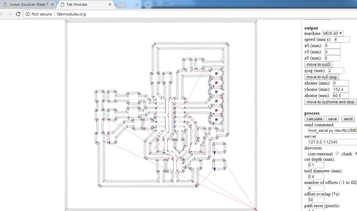
For the milling process I used:
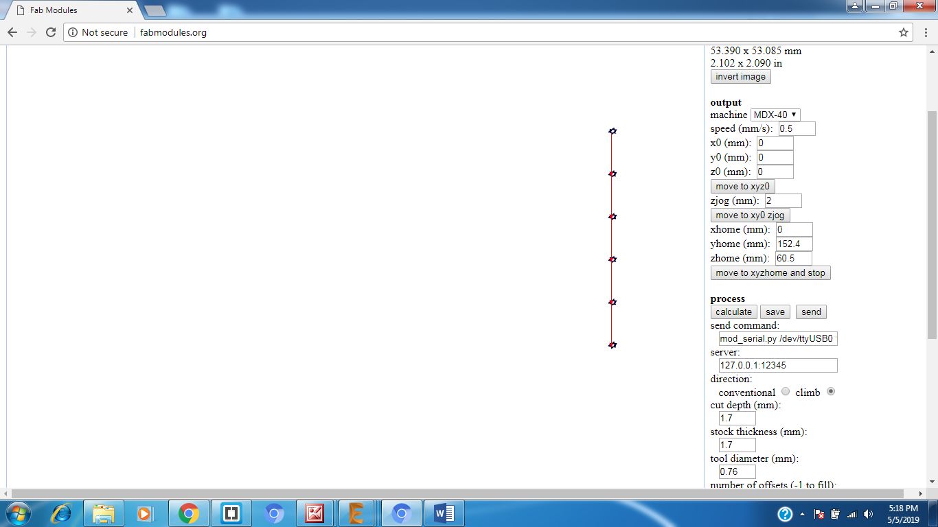
For the drilling process I used:
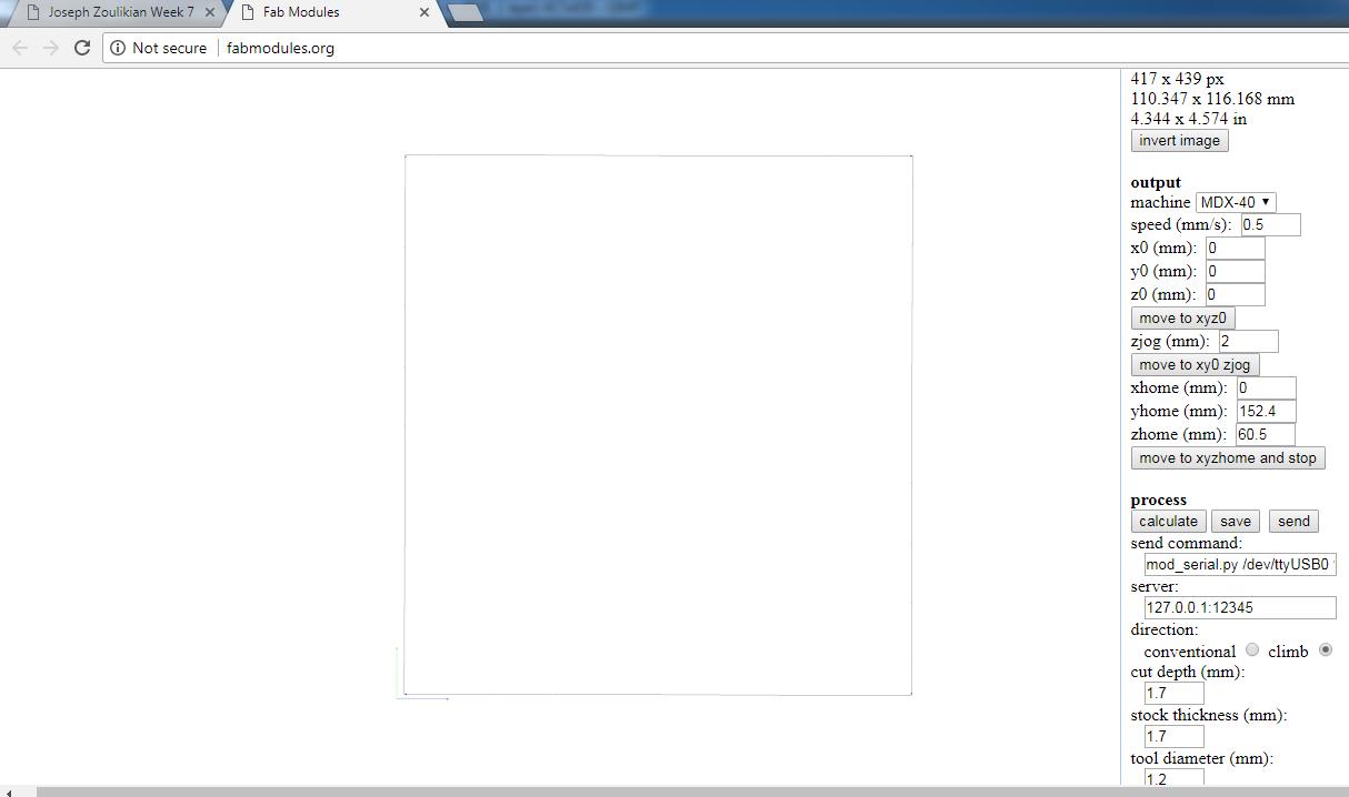
For the Contour Cutting process I used:
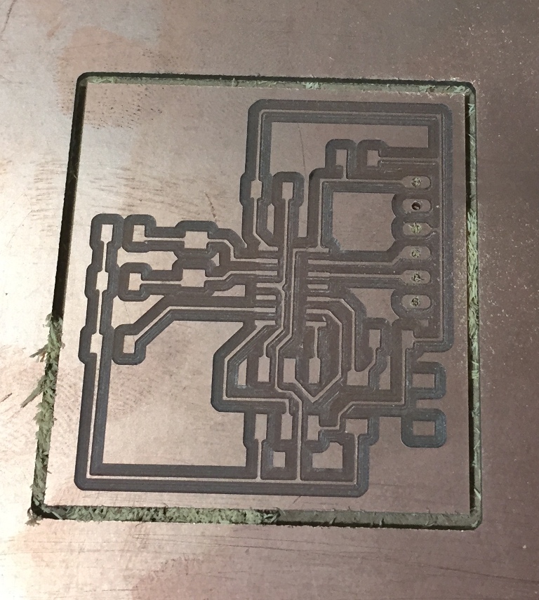
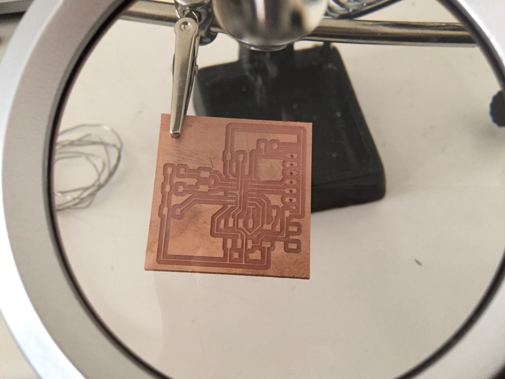
As a result i geenrated the final toolpaths: Outer frame, drills and internal path
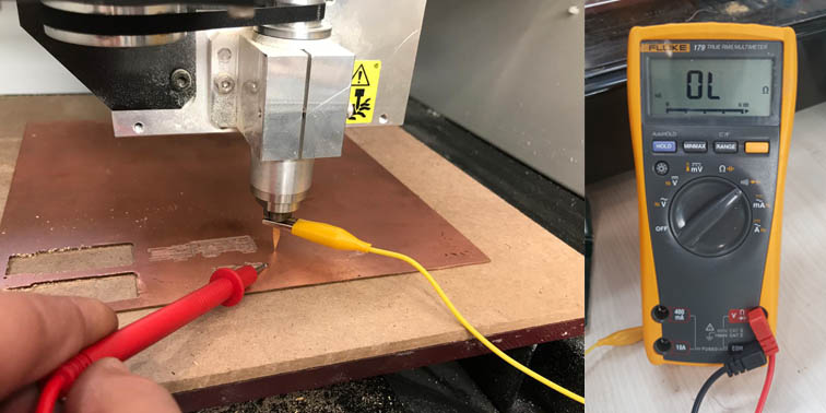
To zeroing the level of the tool, I used the miltimeter to have a precise zeroing because the board copper is very thin. I moved down the tool by commending the -Z down to minimum increment to hear the bepper of the multimeter.
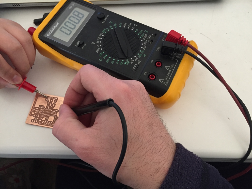
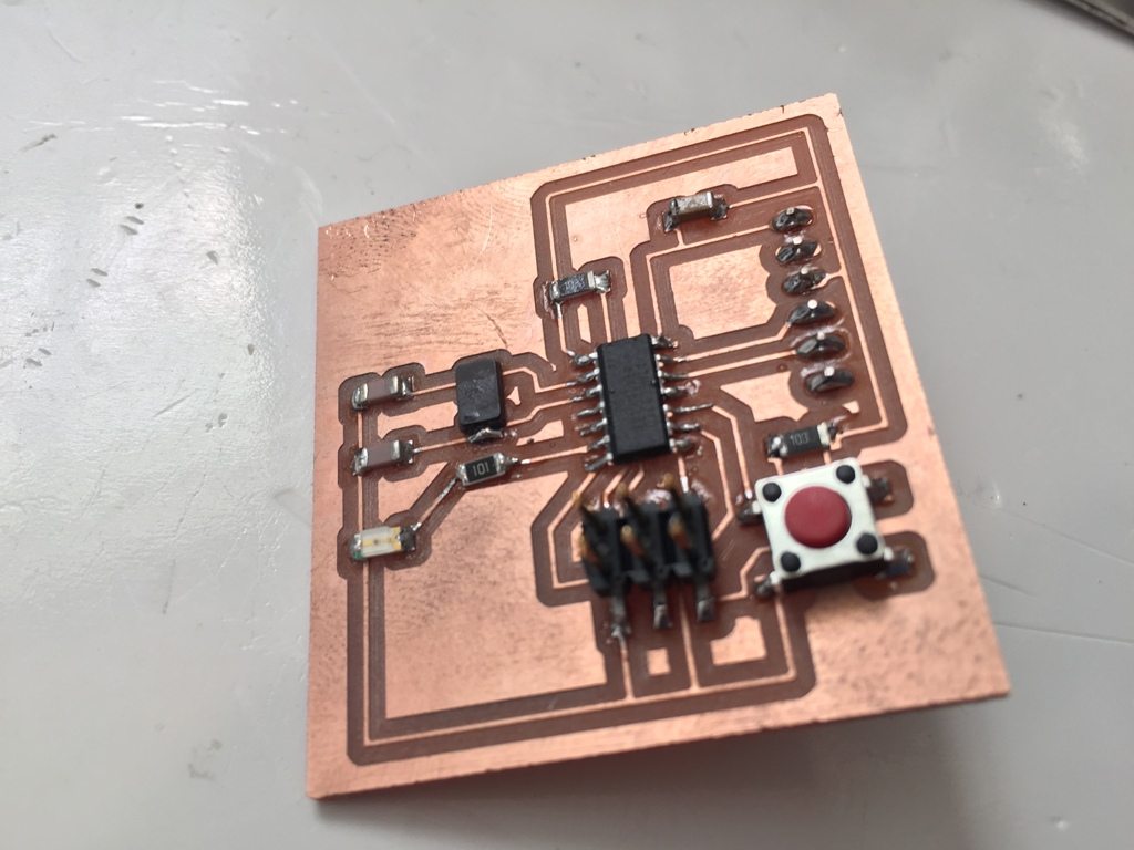
Before starting the soldering of the components I tested the continuity of the wiring between the different pins.
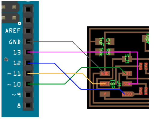
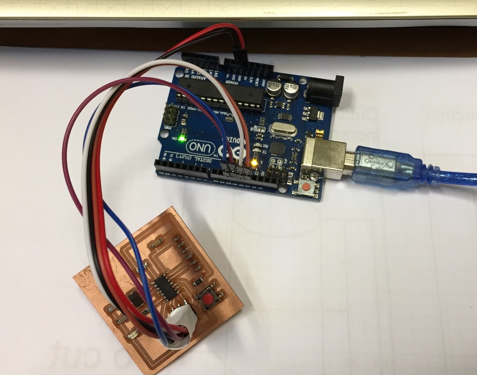
Wiring Arduino Hello Board:
Arduino Setup:
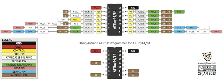
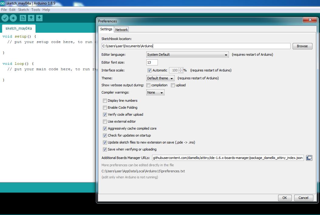
I installed ATtiny44 board on the Arduino IDE. I inserted this link: "https://raw.githubusercontent.com/damellis/attiny/ide-1.6.x-boards-manager/package_damellis_attiny_index.json" in the additional board URL then tools boards manager.
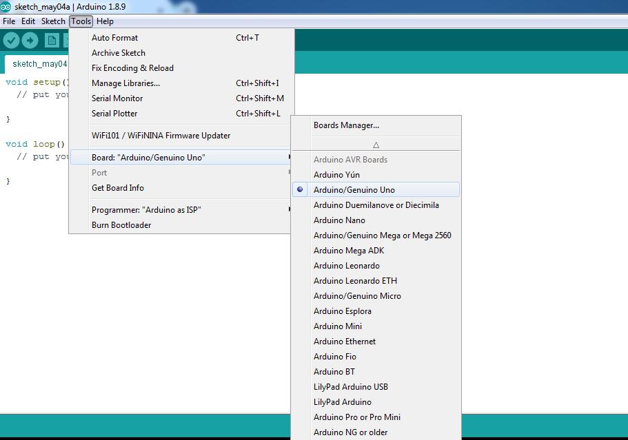
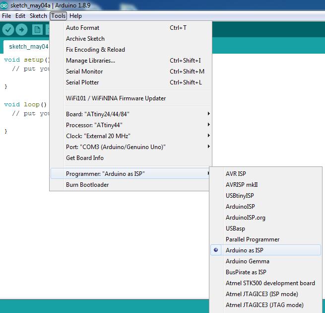
After that I installed ATtiny program, go to tools set the board "ATtiny24/44/84", the processor to "ATtiny44", the clock to "External 20 Mhz", "Arduino as ISP".
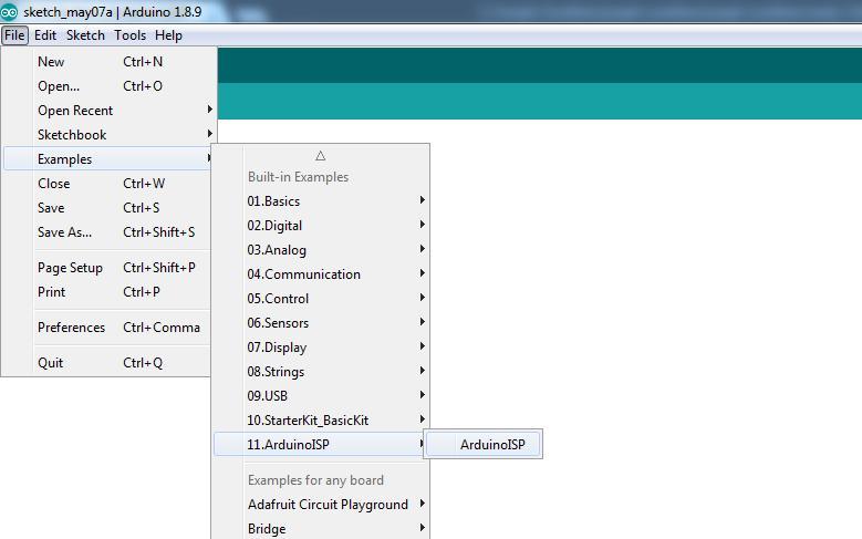
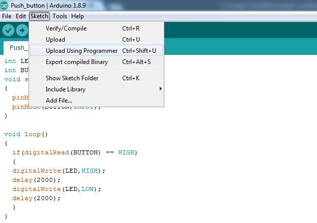
After doing the "burn bootloader" step. I selected "Examples", "ArduinoISP", "ArduinoISP" to inform the Arduino that it will be used as "Programmer".
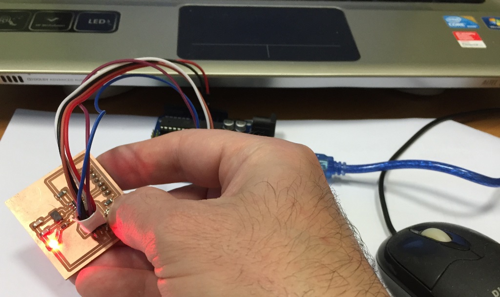
According to the Arduino program, when I press the "Reset Button", the "LED" will turn "On".
The Schematic in Eagle,
The Board in Eagle,
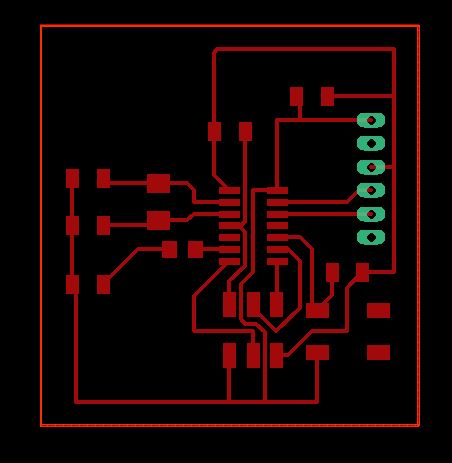
The Internal Path,
The drills,
The External Path,
The Arduino Code to turn on the Red LED,
External path in png,
Internal path in png,
Holes path in png.

This work is licensed under a Creative Commons Attribution 4.0 International License.