Personal Reflection: What I Learned
Working with UART serial communication between XIAO RP2040 boards taught me the importance of proper signal routing and common ground references. I learned that simple wired communication can be more reliable than complex wireless protocols for short-distance applications.
Networking and Communications
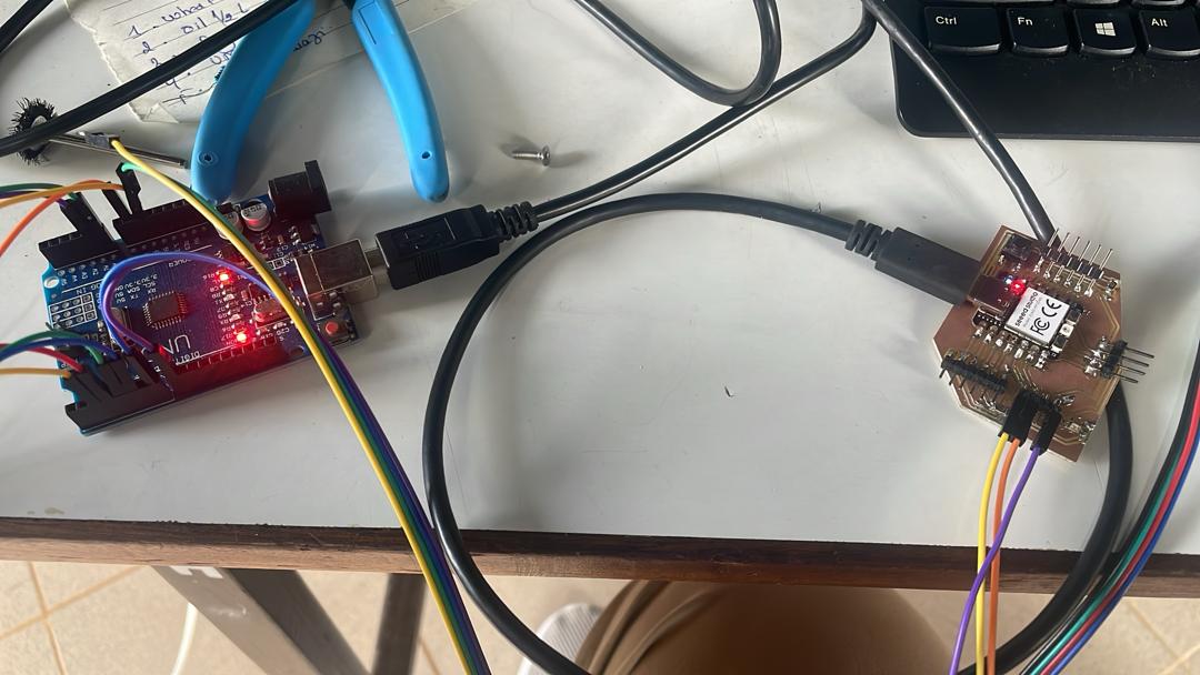
In this week's assignment, I explored serial communication between two microcontrollers - a my board Seeed Studio XIAO RP2040 and an Arduino Uno. i created a chat system where the two devices could exchange messages bidirectionally, and later evolved into a button-controlled stepper motor system.
Components Used
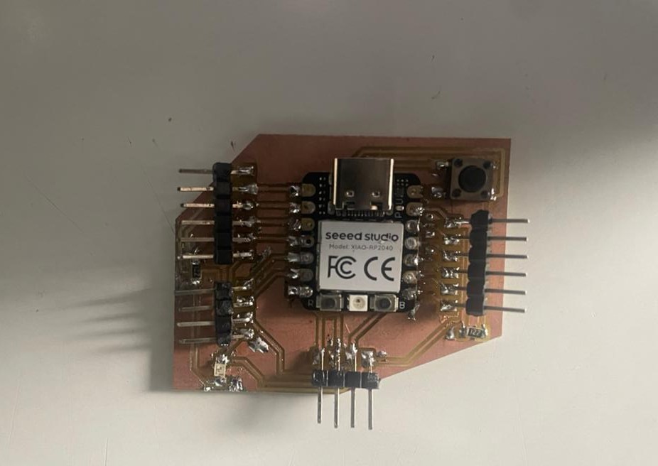
my XIAO RP2040
Raspberry Pi-based microcontroller board with multiple serial options
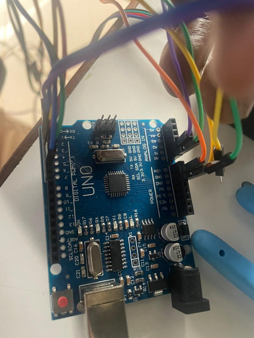
Arduino Uno
Classic ATmega328P board for receiving serial commands
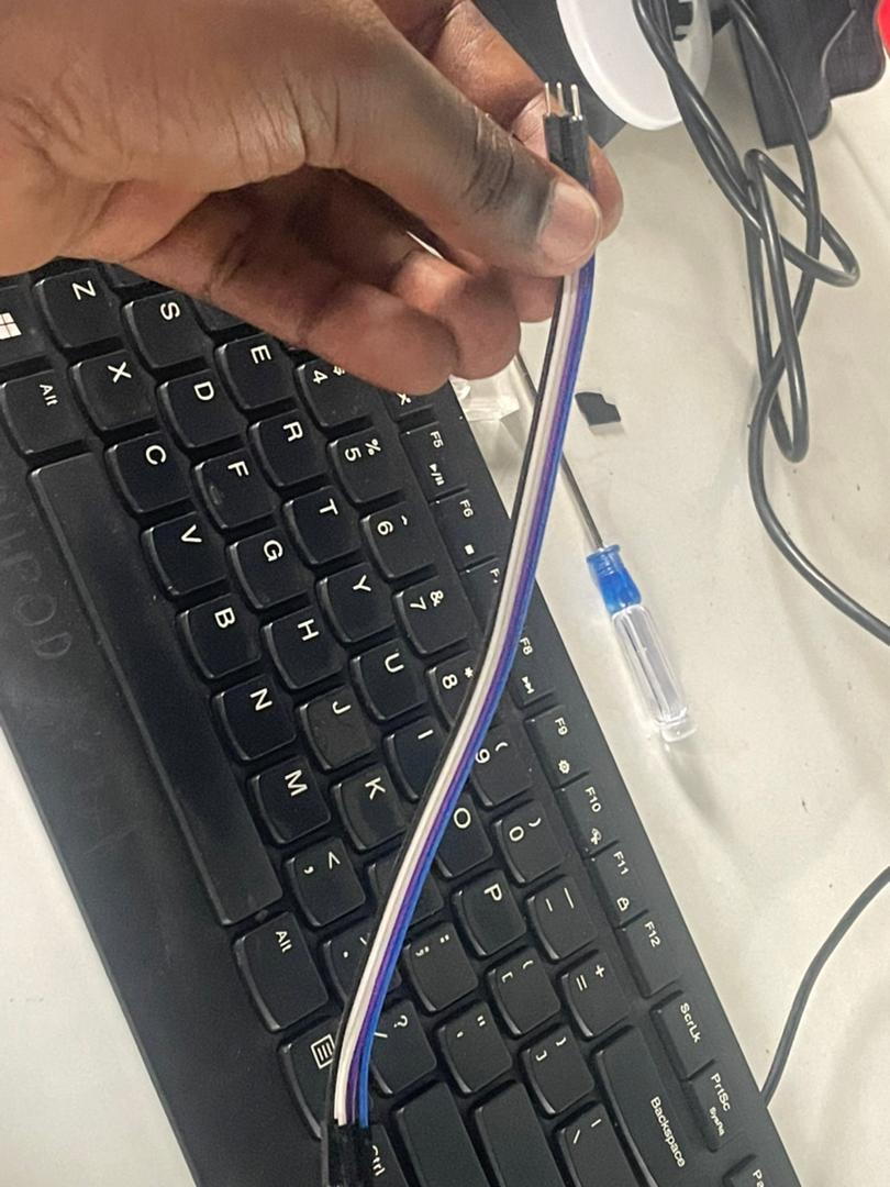
Jumper Wires
For making serial connections between boards
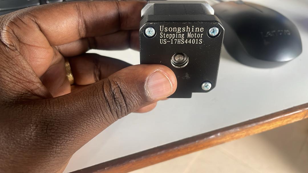
Stepper Motor
for moving
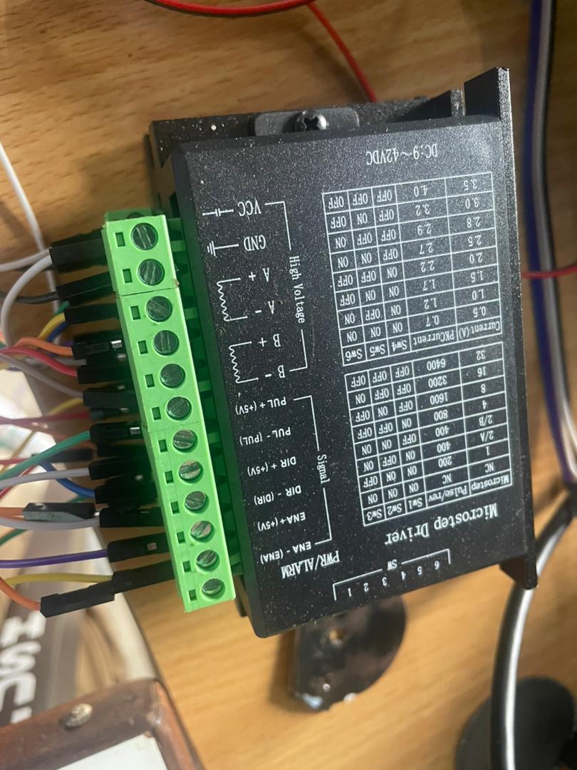
Microstep Driver
For programming and power supply
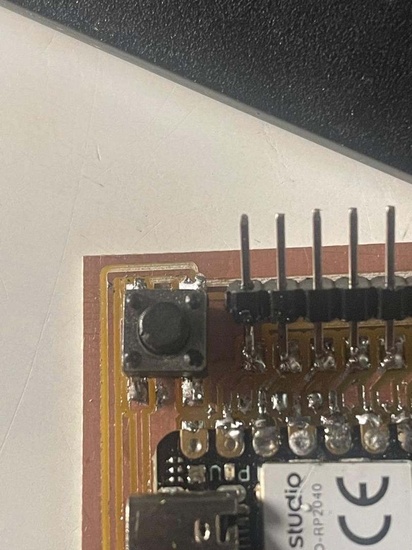
my building in button xiao
fro operation the stepper motor
Initial Challenges Encountered
🚫 Challenge 1: XIAO RP2040 Hardware Serial Not Working
The first major challenge I faced was that the hardware serial pins (RX/TX) on my XIAO RP2040 were not functioning properly. When I tried to use the default Serial1 on pins d6 and d7, I couldn't establish communication with the Arduino Uno.
Symptoms:
- No data transmission between devices
- Serial monitor showing no incoming messages
- Hardware serial pins appeared to be unresponsive
✅ Solution 1: Implementing SoftwareSerial
To overcome the hardware serial issue, I decided to use the SoftwareSerial library, which allowed me to use any digital pins for serial communication.
Steps taken:
- Added SoftwareSerial.h
- Selected alternative pins (D4 and D5 on XIAO)
- Configured SoftwareSerial with same baud rate on both devices
Understanding SoftwareSerial Library
What is SoftwareSerial? The SoftwareSerial library allows you to create serial ports on any digital pins of your microcontroller. This is especially useful when:
- Your hardware serial pins are already in use
- You need multiple serial connections
- Hardware serial pins are not functioning properly (as in my case)
- You want flexibility in pin assignment
🚫 Challenge 2: Arduino Uno Conflicts
The second challenge arose when trying to use certain pins on the Arduino Uno for SoftwareSerial. Some pin combinations caused conflicts with other functionalities or simply didn't work reliably.
Issues faced:
- Interference with hardware serial (pins 0 and 1)
- Some pin combinations resulted in garbled data
- Timing issues with certain pin selections
✅ Solution 2: Finding Compatible Pin Configuration
Through experimentation, I found that using pins 7 and 8 on the Arduino Uno for SoftwareSerial provided stable communication.
Final working configuration:
- XIAO RP2040: D4 (RX) and D5 (TX)
- Arduino Uno: Pin 8 (RX) and Pin 7 (TX)
- Proper cross-connection: TX→RX and RX→TX
Connection
| XIAO RP2040 | Connection | Arduino Uno |
|---|---|---|
| D5 (TX) | → | Pin 8 (RX) |
| D4 (RX) | → | Pin 7 (TX) |
| GND | ↔ | GND |
Final Working Code
XIAO RP2040 Code
// XIAO RP2040 - Simple Chat
#include <SoftwareSerial.h>

// Define SoftwareSerial pins
const int RX_PIN = 6;  // D4 on XIAO RP2040
const int TX_PIN = 7;  // D5 on XIAO RP2040
SoftwareSerial mySerial(RX_PIN, TX_PIN);

void setup() {
  Serial.begin(9600);
  mySerial.begin(9600);

  Serial.println("XIAO Chat Ready!");
  Serial.println("Type messages to send to Arduino Uno");

  // Say hello
  mySerial.println("Hello from XIAO!");
}

void loop() {
  // If we receive something from Uno, display it
  if (mySerial.available()) {
    String message = mySerial.readStringUntil('\n');
    Serial.print("Uno says: ");
    Serial.println(message);
  }

  // If user types something, send it to Uno
  if (Serial.available()) {
    String message = Serial.readStringUntil('\n');
    mySerial.println(message);
    Serial.print("You said: ");
    Serial.println(message);
  }
}
Arduino Uno Code
#include <SoftwareSerial.h>

// Use pins that work for you
const int RX_PIN = 8;  // Connect to XIAO TX (D5)
const int TX_PIN = 7;  // Connect to XIAO RX (D4)
SoftwareSerial mySerial(RX_PIN, TX_PIN);

void setup() {
  Serial.begin(9600);    // For Serial Monitor
  mySerial.begin(9600);  // For XIAO communication

  Serial.println("Arduino Uno Chat Ready!");
  Serial.println("Type in Serial Monitor to send to XIAO");

  // Send hello through SoftwareSerial
  mySerial.println("Hello from Arduino!");
}

void loop() {
  // Check for messages from XIAO
  if (mySerial.available()) {
    String message = mySerial.readStringUntil('\n');
    Serial.print("XIAO says: ");
    Serial.println(message);
  }

  // Check for input from Serial Monitor
  if (Serial.available()) {
    String message = Serial.readStringUntil('\n');
    mySerial.println(message);
    Serial.print("You sent: ");
    Serial.println(message);
  }
}
IAO RP2040 Button Control to Arduino Uno Stepper Motor
Creating a button-controlled stepper motor system with serial communication between two microcontrollers
What I Built
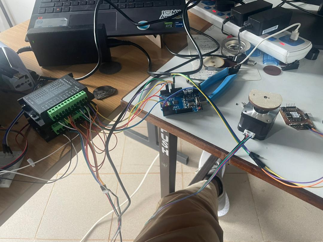
I created a networked system where a button on my XIAO RP2040 controls a stepper motor connected to an Arduino Uno. When the button is pressed, the XIAO sends serial commands to the Uno, which then moves the stepper motor between 0° and 90° positions.
How I Connected Everything
The project involves two separate circuits connected via serial communication:
XIAO RP2040 Connections:
| Component | XIAO Pin | Function |
|---|---|---|
| Button | D2 | User input (with internal pull-up) |
| TX (Serial) | D5 (GPIO 7) | Send data to Uno |
| RX (Serial) | D4 (GPIO 6) | Receive data from Uno |
| GND | GND | Common ground |
Arduino Uno to Stepper Driver:
| Component | Arduino Pin | Function |
|---|---|---|
| STEP | Pin 2 | Step signal to driver |
| DIR | Pin 3 | Direction control |
| ENABLE | A0 | Enable/disable motor |
| TX | Pin 1 | Send data to XIAO |
| RX | Pin 0 | Receive data from XIAO |
Important: TX from XIAO connects to RX on Uno, and RX from XIAO connects to TX on Uno (crossed connection). Don't forget to connect the grounds together!
How it's Works
The system operates using serial communication protocol:
- Button press on XIAO triggers a toggle between 0° and 90° positions
- XIAO sends serial command ("1,0" or "1,90") via SoftwareSerial on D4/D5
- Arduino Uno receives command through hardware serial (pins 0/1)
- Uno processes command and moves stepper motor to specified angle
- Built-in LED on XIAO indicates current position (ON = 90°, OFF = 0°)
XIAO RP2040 Code
This code handles button input and sends serial commands:
#include <SoftwareSerial.h>

// Define SoftwareSerial on D4(RX) and D5(TX)
const int RX_PIN = 6;  // D4 on XIAO RP2040
const int TX_PIN = 7;  // D5 on XIAO RP2040
SoftwareSerial mySerial(RX_PIN, TX_PIN);

const int BUTTON_PIN = 2;     // Button on D2 (GPIO 2)
const int LED_PIN = LED_BUILTIN;  // Built-in LED for status
bool motorPosition = false;   // false = 0°, true = 90°

void setup() {
  // Initialize USB Serial for debugging
  Serial.begin(115200);
  while (!Serial && millis() < 5000);

  // Initialize SoftwareSerial for Arduino Uno communication
  mySerial.begin(9600);

  // Setup button and LED
  pinMode(BUTTON_PIN, INPUT_PULLUP);
  pinMode(LED_PIN, OUTPUT);

  delay(1000);

  Serial.println("XIAO RP2040 Ready");
  Serial.println("Using D4(RX) and D5(TX) for serial communication");
  Serial.println("Press button D2 to toggle motor position");
}

void loop() {
  // Button handling with debouncing
  static bool lastButtonState = HIGH;
  static unsigned long lastDebounceTime = 0;
  const unsigned long debounceDelay = 50;

  bool reading = digitalRead(BUTTON_PIN);

  if (reading != lastButtonState) {
    lastDebounceTime = millis();
  }

  if ((millis() - lastDebounceTime) > debounceDelay) {
    static bool buttonState = HIGH;

    if (reading != buttonState) {
      buttonState = reading;

      if (buttonState == LOW) {
        // Button pressed - toggle position
        motorPosition = !motorPosition;

        if (motorPosition) {
          mySerial.println("1,90");
          Serial.println("Sent to Uno: 1,90");
          digitalWrite(LED_PIN, HIGH);
        } else {
          mySerial.println("1,0");
          Serial.println("Sent to Uno: 1,0");
          digitalWrite(LED_PIN, LOW);
        }

        // Wait for button release
        while (digitalRead(BUTTON_PIN) == LOW) {
          delay(10);
        }
      }
    }
  }

  lastButtonState = reading;
}
Arduino Uno Code (Simplified)
This code receives commands and controls the stepper motor:
#include <SoftwareSerial.h>

// Constants and definitions
const int numSteppers = 1;
const int STEP_PINS[numSteppers] = {2};
const int DIR_PINS[numSteppers] = {3};
const int ENABLE_PINS[numSteppers] = {A0};

// Position tracking
long currentStepperPositions[numSteppers] = {0};
int stepperSpeed[numSteppers] = {500};

// Microstep settings
const int MICROSTEPS = 16;
const int STEPS_PER_REV = 12.5 * MICROSTEPS;

void setup() {
  Serial.begin(9600);

  // Initialize stepper motor pins
  pinMode(STEP_PINS[0], OUTPUT);
  pinMode(DIR_PINS[0], OUTPUT);
  pinMode(ENABLE_PINS[0], OUTPUT);

  // Enable the stepper motor
  digitalWrite(ENABLE_PINS[0], LOW);

  Serial.println("Arduino Uno Stepper Controller Ready");
}

void loop() {
  if (Serial.available()) {
    String input = Serial.readStringUntil('\n');
    input.trim();

    Serial.println("Received: " + input);
    processCommand(input);
  }
}

void processCommand(String command) {
  int commaIndex = command.indexOf(',');
  if (commaIndex > 0) {
    String motorStr = command.substring(0, commaIndex);
    String angleStr = command.substring(commaIndex + 1);

    int motorNum = motorStr.toInt();
    float angle = angleStr.toFloat();

    if (motorNum == 1) {
      Serial.print("Moving to angle: ");
      Serial.println(angle);
      moveToAngle(angle);
    }
  }
}

void moveToAngle(float angle) {
  long targetSteps = angleToSteps(angle);
  moveToPosition(targetSteps);
}

long angleToSteps(float angle) {
  return (long)((STEPS_PER_REV * angle) / 360.0);
}

void moveToPosition(long targetSteps) {
  long stepsToMove = targetSteps - currentStepperPositions[0];

  if (stepsToMove == 0) return;

  // Set direction
  bool forward = (stepsToMove > 0);
  digitalWrite(DIR_PINS[0], forward ? HIGH : LOW);

  // Calculate delay
  int stepDelayMicros = 1000000 / stepperSpeed[0];

  // Move the motor
  long stepsAbsolute = abs(stepsToMove);
  for (long i = 0; i < stepsAbsolute; i++) {
    digitalWrite(STEP_PINS[0], HIGH);
    delayMicroseconds(2);
    digitalWrite(STEP_PINS[0], LOW);
    delayMicroseconds(stepDelayMicros - 2);
  }

  // Update position
  currentStepperPositions[0] = targetSteps;

  Serial.print("Moved to position: ");
  Serial.print(currentStepperPositions[0]);
  Serial.println(" steps");
}
Video Demonstration
Communication Protocol Explained
XIAO RP2040 Side:
- Uses SoftwareSerial library for flexible pin assignment
- Monitors button state with debouncing to prevent false triggers
- Sends formatted commands: "1,angle" (e.g., "1,90" or "1,0")
- Uses built-in LED to indicate current position
Arduino Uno Side:
- Uses hardware serial for reliable communication
- Parses incoming commands to extract motor number and angle
- Converts angle to steps based on microstepping configuration
- Controls stepper motor using STEP and DIR signals
Serial Configuration:
- Baud rate: 9600 (must match on both devices)
- Data format: "motor_number,angle" (e.g., "1,90")
- Line ending: '\n' (newline character)
- Full duplex communication (both directions possible)
Challenges I Faced
Serial Pin Selection
Initially tried using the default Serial1 on XIAO (GP0/GP1) but had conflicts. Solved by switching to SoftwareSerial on D4/D5.
Button Debouncing
The button was triggering multiple times per press. Implemented proper debouncing with a 50ms delay to ensure clean state changes.
Cross-Connection Confusion
Initially connected TX to TX and RX to RX, which didn't work. Remembered that serial communication requires crossed connections (TX to RX).
What I Learned
This project taught me several important concepts about networking and communications:
- Serial communication requires proper TX/RX cross-connection
- SoftwareSerial provides flexibility when hardware serial pins are occupied
- Proper command formatting and parsing is crucial for reliable communication
- Ground connection between devices is essential for serial communication
- Debouncing is critical for reliable button input