Personal Reflection: What I Learned
This week's group work gave us hands-on experience with the entire PCB milling process, from generating toolpaths to operating the milling machine. We now have a better understanding of the design constraints for our future PCB designs. The combination of Mods CE and VPanel software makes the process straightforward, though care must be taken at each step to ensure accurate results.
The design rule tests helped us establish practical guidelines for our future electronics projects, ensuring that we can design PCBs that are both functional and manufacturable with our lab equipment.
KiCad: My XIAO RP2040 PCB Production Adding a Button and Pin to Extend the Microcontroller
I started using the PCB layout with all connections from the Week 6 Assignment
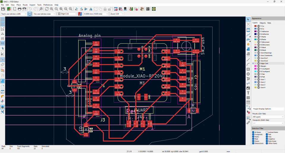
The Design PCB
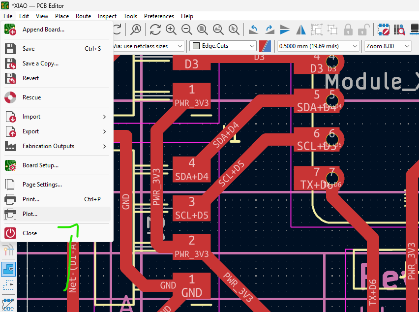
In KiCad, the plotting process involves generating the necessary files for PCB manufacturing from your completed board design. Here's how plotting works in KiCad: After completing your PCB design in KiCad's PCB Editor, you can access the plotting features through the "File" menu by selecting "Plot". The Plot dialog allows you to generate several types of files: Gerber files (the industry standard format for PCB manufacturing) Drill files (for the holes in your PCB) Position files (for component placement) PDF files (for documentation) SVG Files (for the CNC tracing)
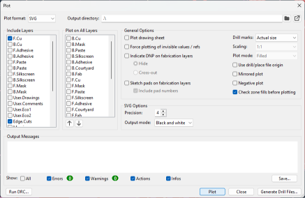
Plot Dialog
For my plot selection, I used the SVG files with F.Cu and Edge Cuts as these are what we need to use with ModsProject.org
Plot Selection
After clicking plot, I had two SVG files: F.Cu and Edge Cuts
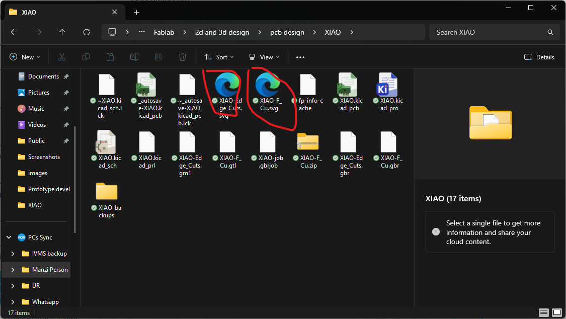
Generated SVG Files
After that, I went to ModsProject.org, then I inserted the SVG for the F.Cu
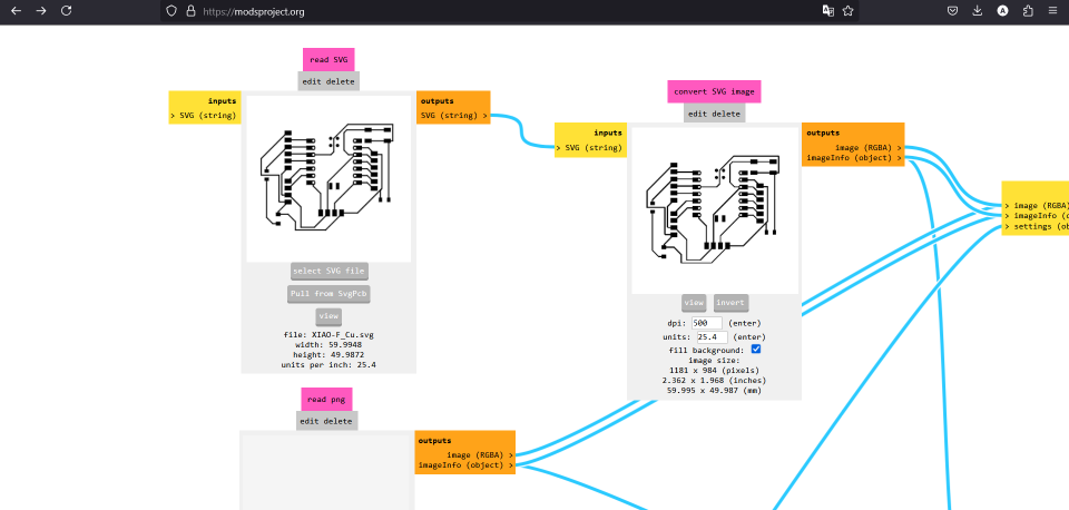
Uploading F.Cu SVG to ModsProject
I selected the invert option to create the traces for the PCB
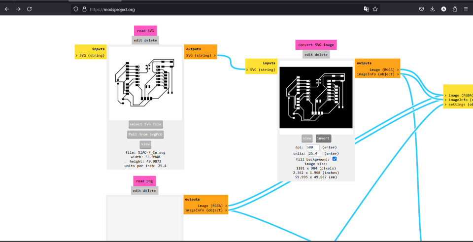
Inverting the Traces
And then I selected the mill option
Selecting Mill Option
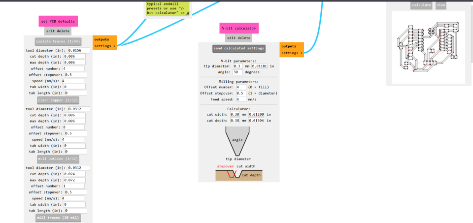
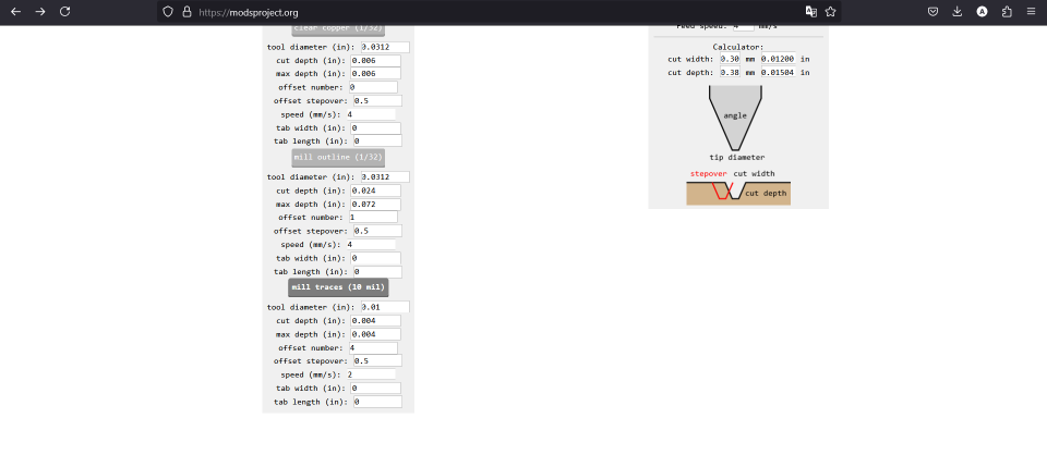
Setting Up Milling Parameters
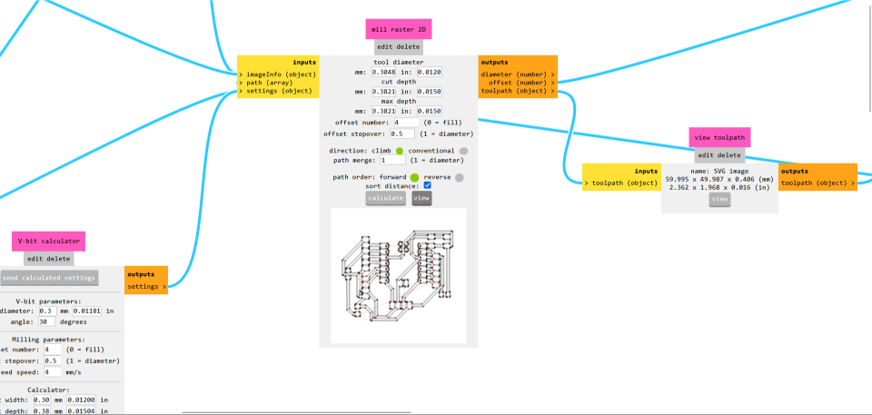
Toolpath Generation
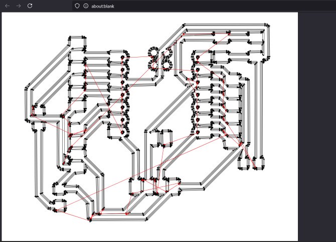
Preview of Toolpaths
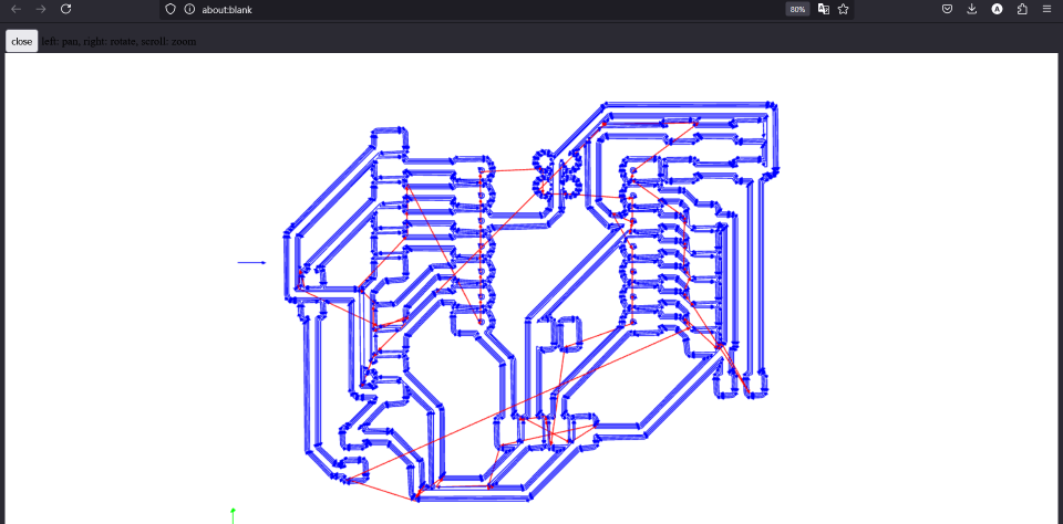
Final Toolpath Configuration
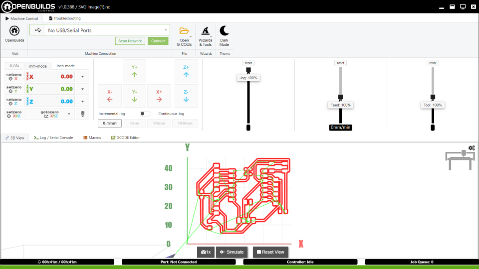
Using OpenBuild to start the milling process
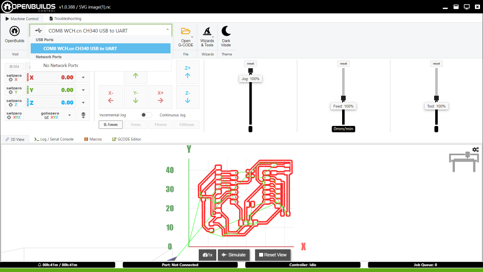
Machine Configuration
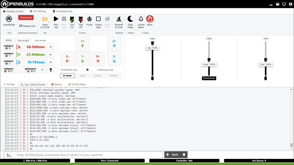
Preparing for Milling
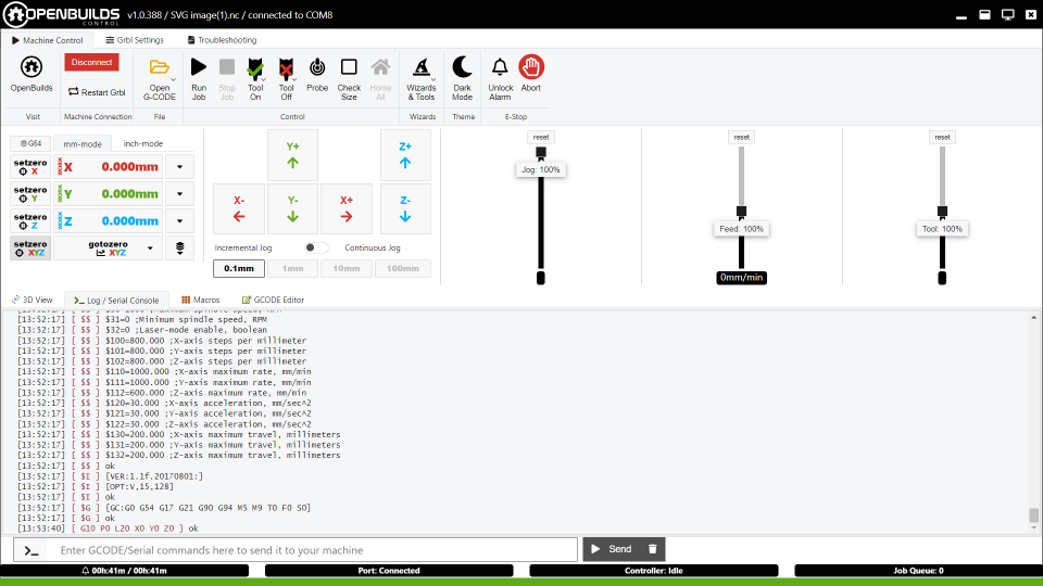
Finalizing Setup
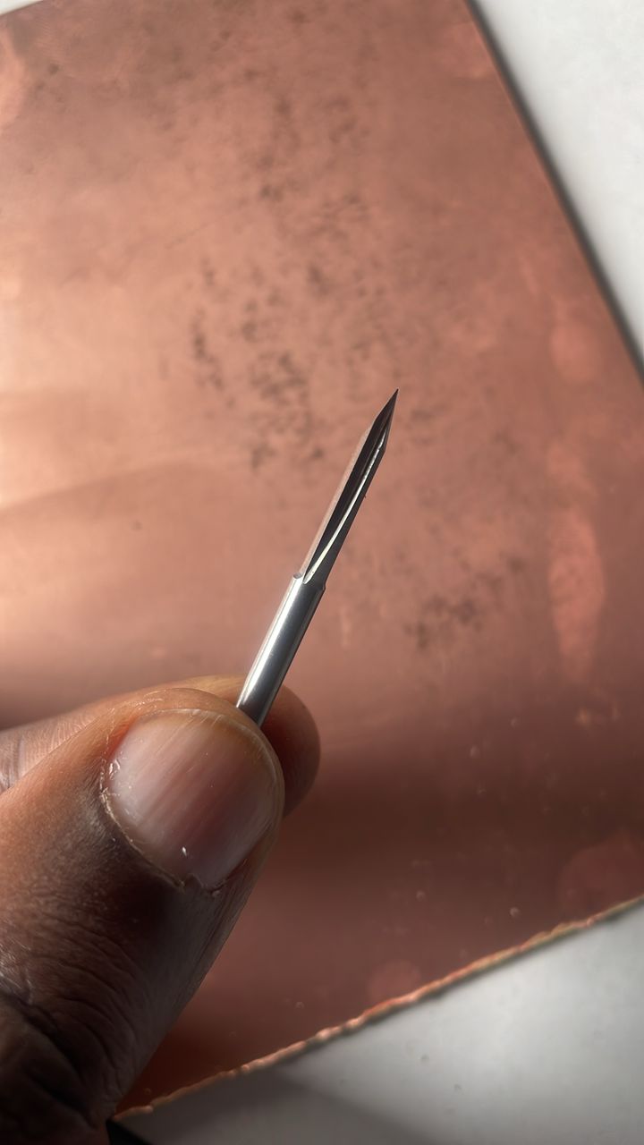
The milling bit used
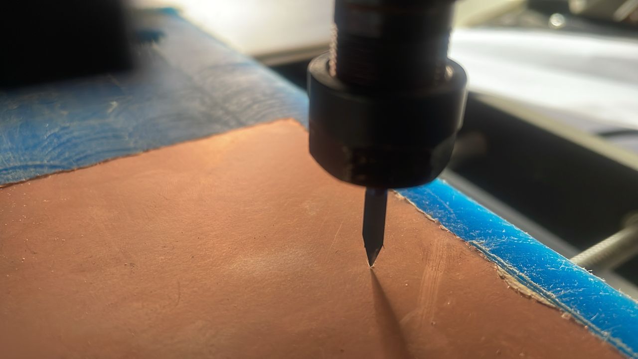
Placing the copper board into the CNC machine
PCB milling in progress
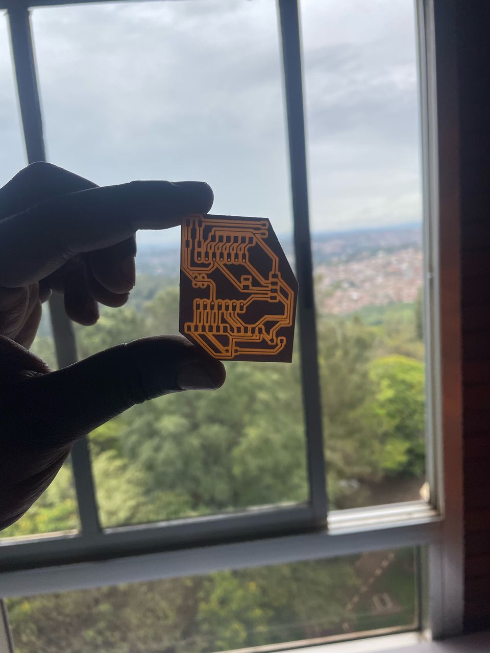
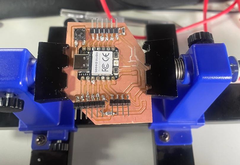
My PCB cleaned and ready for soldering
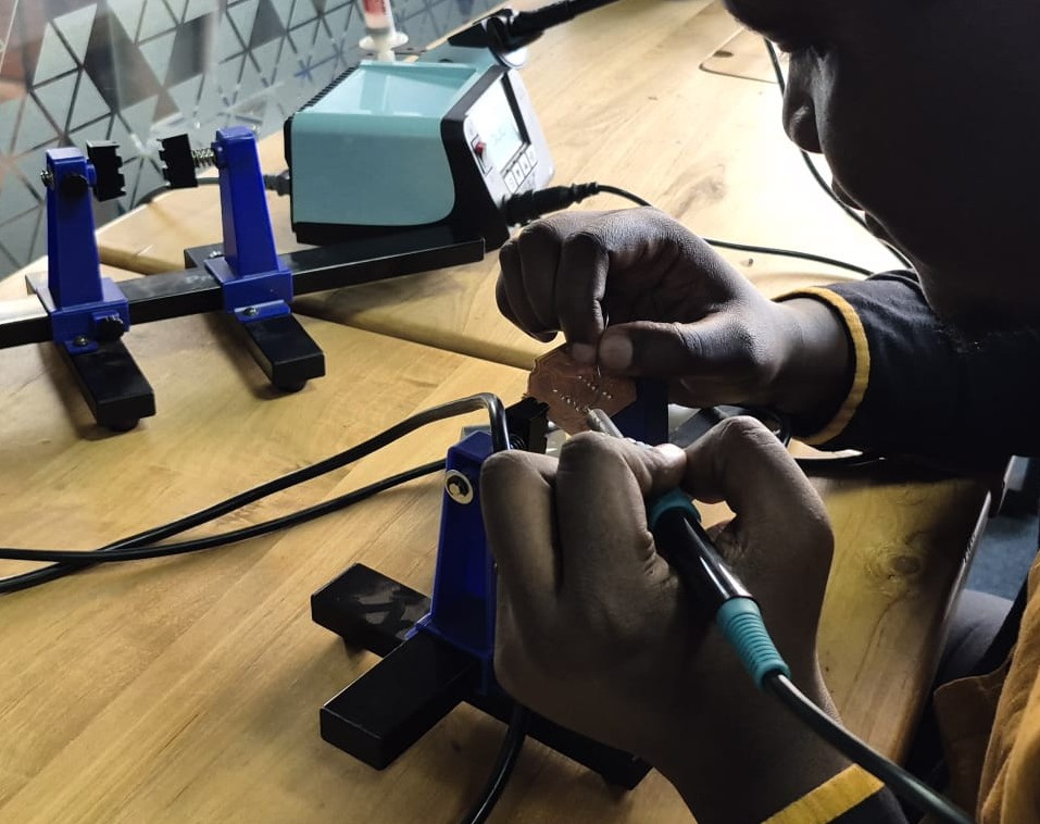
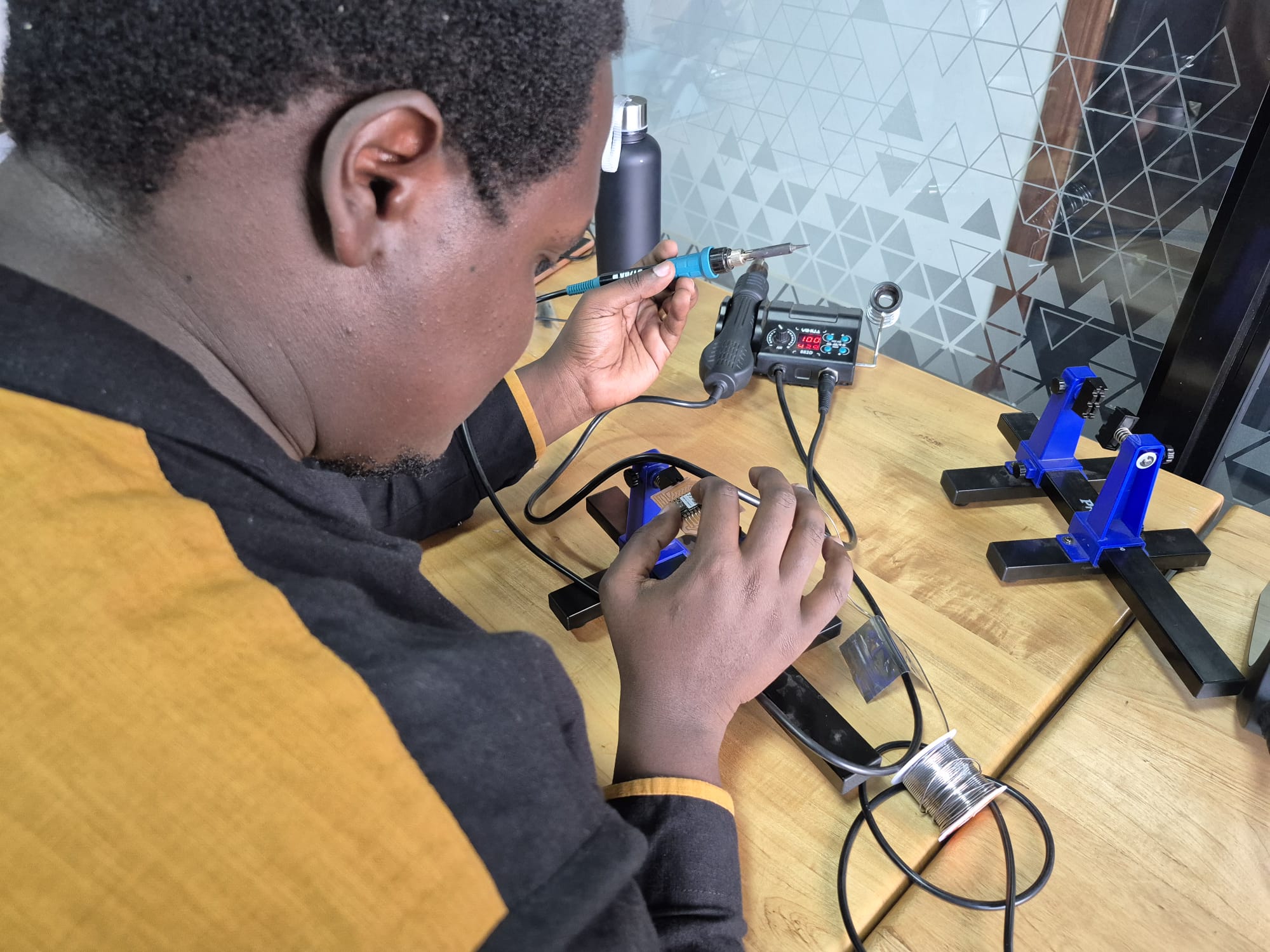
Soldering and Testing My Board
Tools
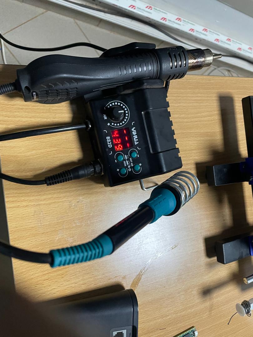
Soldering station
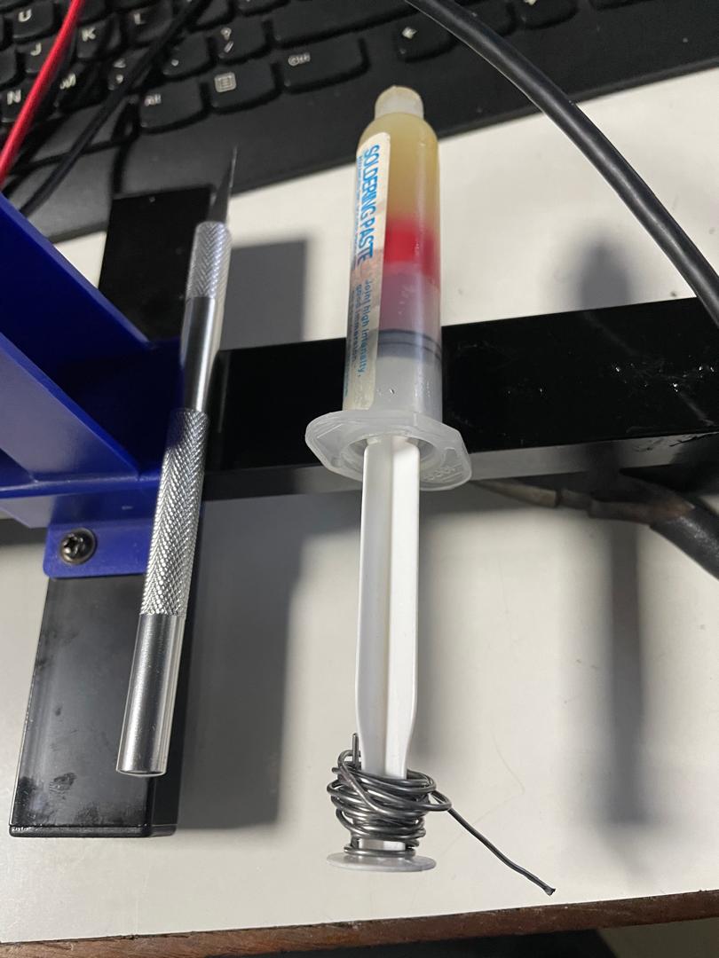
Solder paste
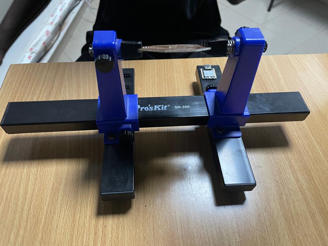
PCB holder
Next, attaching my XIAO to the board
Applying the paste and solder
Used hot air gun and placed the XIAO
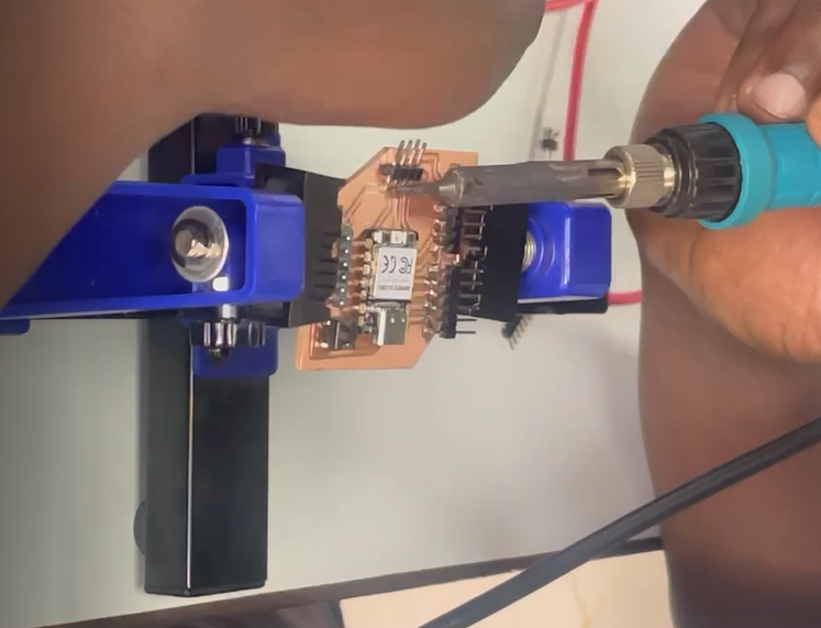
Adding the other components: connectors, button, and resistor
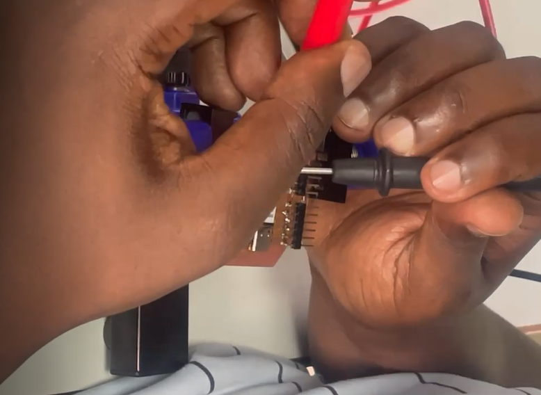
Testing the continuity to prevent short circuits
Almost all components attached
The last part which was a headache (the orange CMD LED), and finally tested the PCB. Youpiiiii!
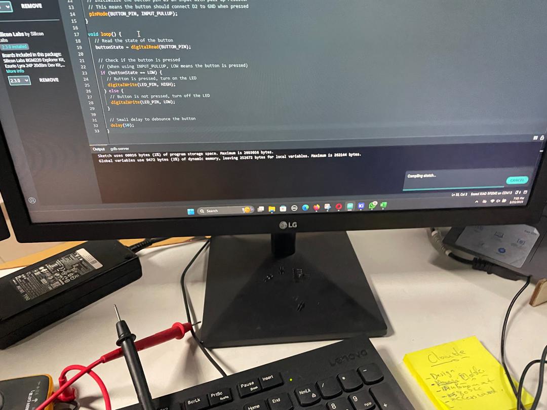
My code to test the PCB and the functionality of the components
Test was successful, and the button and the LED are working
Button and LED Source Code
Here is the simple source code I used to control the LED with the button press on my XIAO RP2040:
#include// Define pin numbers for XIAO RP2040 const int BUTTON_PIN = D2; // Button connected to D2 const int LED_PIN = D1; // LED connected to D1 // Variables int buttonState = 0; // Current state of the button int lastButtonState = 0; // Previous state of the button bool ledState = false; // Current state of the LED void setup() { // Initialize pins pinMode(BUTTON_PIN, INPUT_PULLUP); // Button with pull-up resistor pinMode(LED_PIN, OUTPUT); // LED as output // LED starts off digitalWrite(LED_PIN, LOW); } void loop() { // Read button state buttonState = digitalRead(BUTTON_PIN); // Check if button state changed if (buttonState != lastButtonState) { delay(50); // Simple debounce // If button is pressed (LOW with pull-up) if (buttonState == LOW) { // Toggle LED ledState = !ledState; digitalWrite(LED_PIN, ledState); } // Save button state lastButtonState = buttonState; } delay(10); // Small delay }
This simple code toggles the LED on D1 each time the button on D2 is pressed.