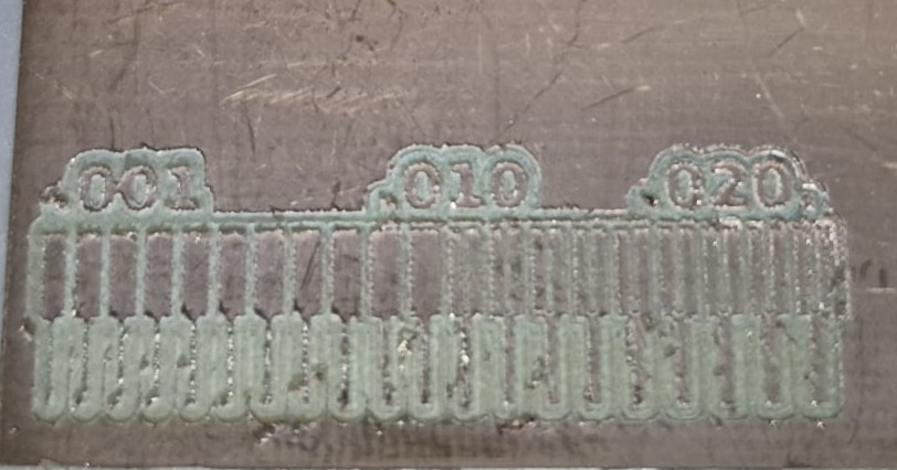
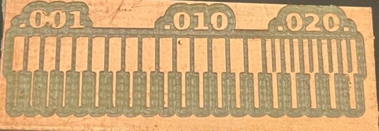
Characterize the design rules for your PCB production process.
Document your work on the group work page and reflect on your individual page what you learned.
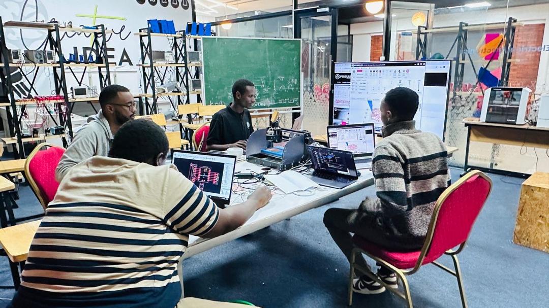
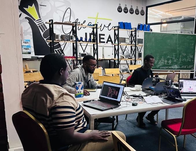
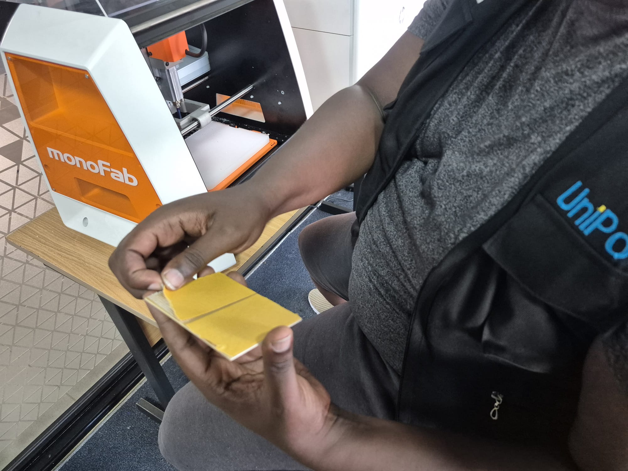
Team members working on PCB milling
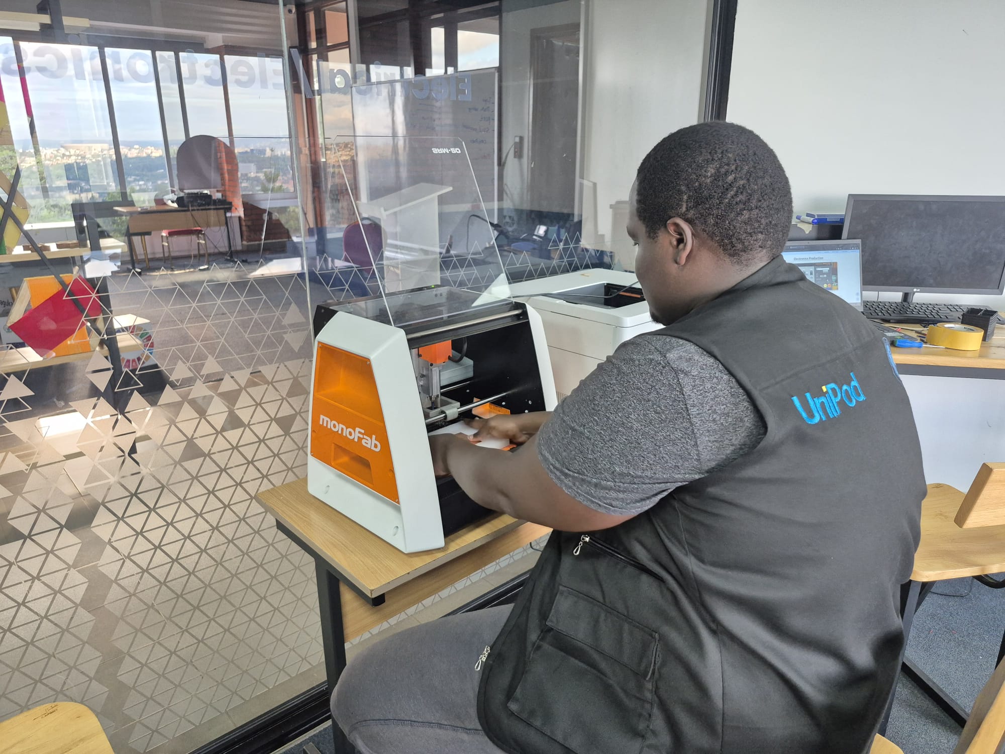
Team discussion during electronics production
Introduction to Electronics Production
Electronics production involves designing and manufacturing electronic components such as resistors, transistors, and PCBs. This week, we focused on understanding the PCB milling process using the Roland SRM-20 machine. We learned about generating toolpaths from PNG files, setting up the machine, and milling test designs to characterize the design rules. The hands-on experience helped us understand the entire workflow from digital design to physical production of circuit boards.
About PCB Fabrication
PCB fabrication includes the entire process from designing the PCB to the final cutting and assembly. The process typically follows these steps:
Designing the PCB layout
Converting the design into toolpaths
Milling the copper traces
Drilling holes for component placement
Cutting the board outline
Soldering components
Testing the assembled circuit
In our lab, we use a subtractive manufacturing approach, where a CNC mill removes copper from a copper-clad board to create the circuit traces.
Types of PCBs
There are several types of PCBs used in electronics production:
Single-Layer PCB: Copper traces on only one side of the board
Double-Layer PCB: Copper traces on both sides with connections between layers
Multi-Layer PCB: Multiple layers of copper traces with connections between them
Rigid PCB: Standard inflexible circuit boards
Flexible PCB: Bendable circuit boards for specialized applications
For our design rule tests, we worked with single-layer FR-1 copper-clad boards, which are commonly used for prototyping.
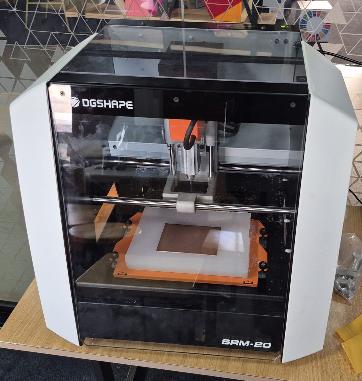
Roland MonoFab SRM-20 Milling Machine
The Roland MonoFab SRM-20 is a compact and precise desktop CNC milling machine designed for PCB fabrication, prototyping, and small-scale manufacturing. It's widely used in electronics production, engineering, and education for milling PCBs, plastic, and soft metals.
Roland MonoFab SRM-20 CNC Milling Machine
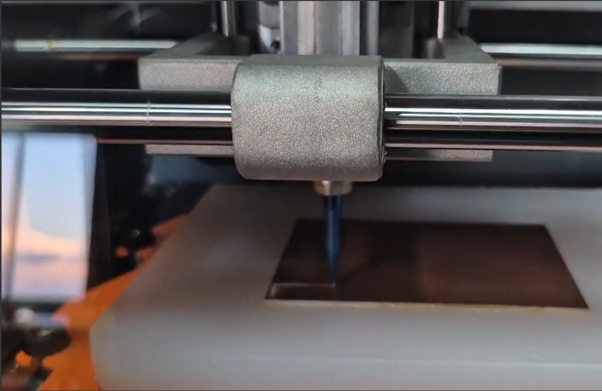
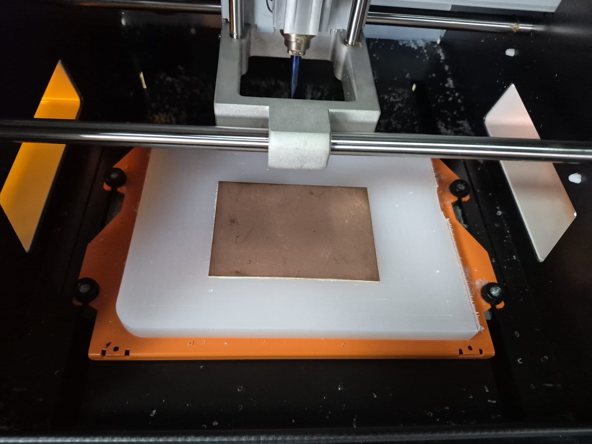
SRM-20 during the milling process
Key Features
Software Support: Works with SRP Player, VPanel, and Mods for generating toolpaths
File Format Support: Accepts RML-1 and G-Code commands
Material Compatibility: Works with PCB boards, acrylic, wax, and wood
Connectivity: USB connection to computer for smooth operation
Precision: High accuracy for detailed PCB traces
Form Factor: Compact design for desktop use
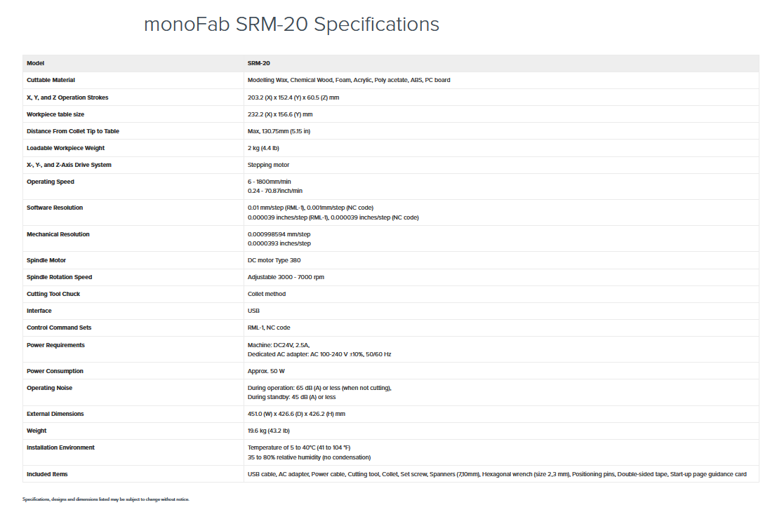
Technical Specifications
The SRM-20 offers precise capabilities for PCB milling:
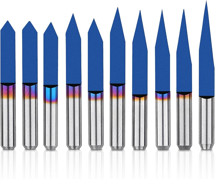
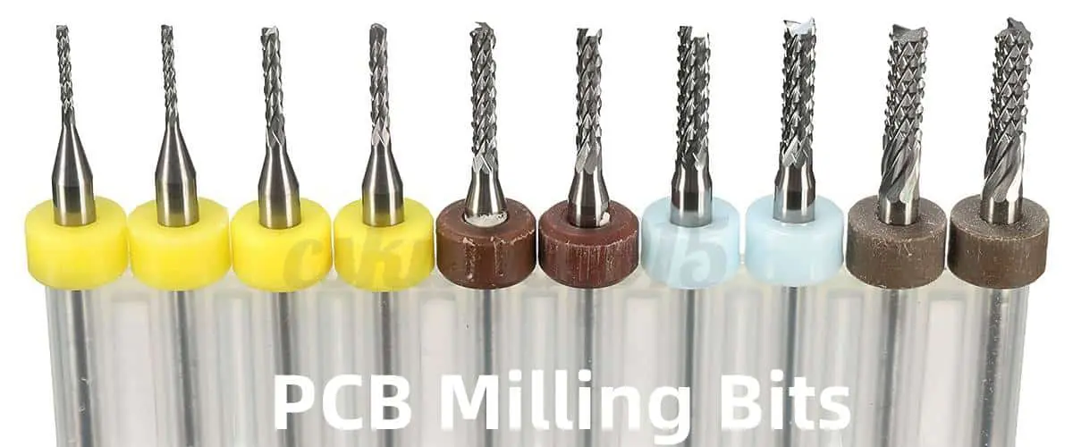
The SRM-20 uses various tools for different aspects of PCB fabrication:
V-Bit: Used for engraving and fine detailing on PCB surfaces
Bit: Used for milling and cutting the outer profile of the PCB
Additional Tools
Several additional tools are necessary for the PCB fabrication process:
Double-Sided Tape: For securing the PCB to the milling machine bed
Cutter: Used for cutting tape or unwanted material
Brush: For cleaning dust and debris from the PCB
Allen Key: Used to tighten or loosen the collet
Spatula: Helps safely remove the PCB without damage
Scissors: For cutting tape or other materials
FR-1 Copper Clad: The raw material for PCB milling
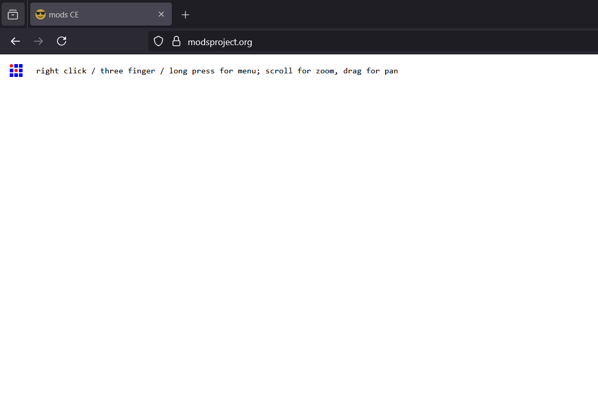
Mods CE Software
Mods CE is an online platform used for generating toolpaths from SVG files for PCB milling and other fabrication processes. It allows users to convert design files into machine-readable formats, ensuring precise cutting and engraving.
The platform supports various customizable settings such as tool diameter, cutting depth, and speed, making it highly useful for PCB fabrication, engraving, and other CNC-based applications.
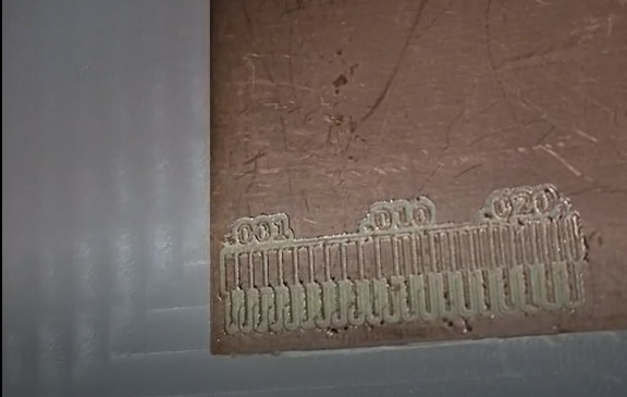
For our design rule tests, we used the test files provided by Neil:
route traces test file
cut traces test file
Toolpath Generation Process
We used Mods CE to generate toolpaths for our PCB milling:
Step 1: Visit the Mods CE website
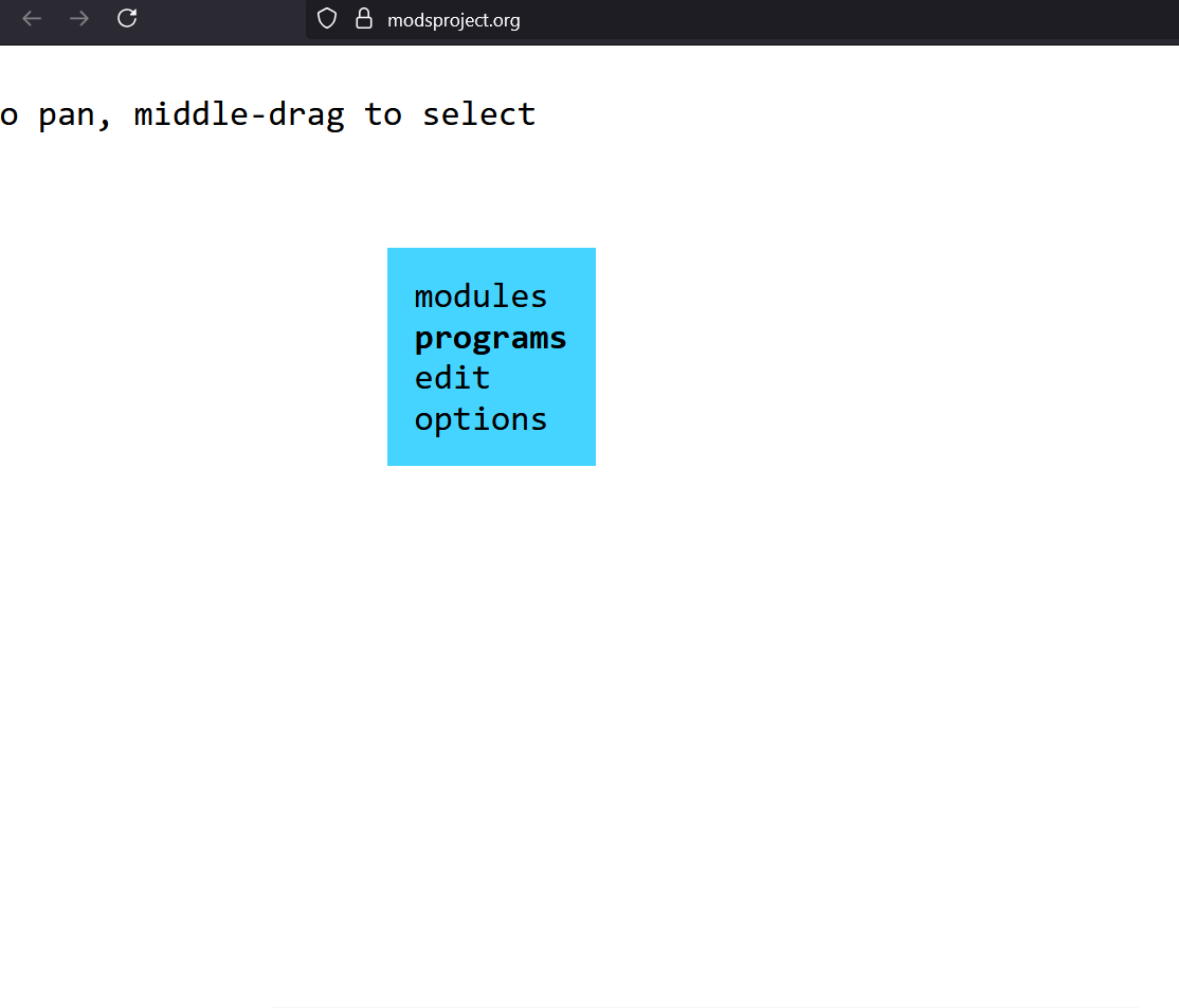
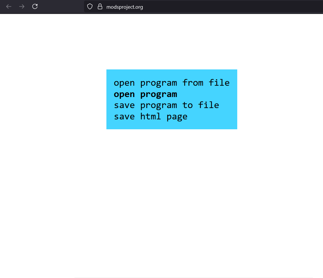
Step 2: Right-click and select programs from the menu
Step 3: Click on "Open Program" and ensure the PCB milling machine is connected
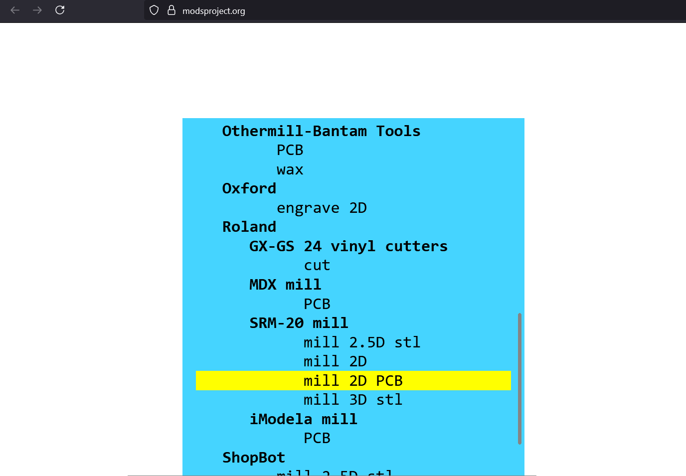
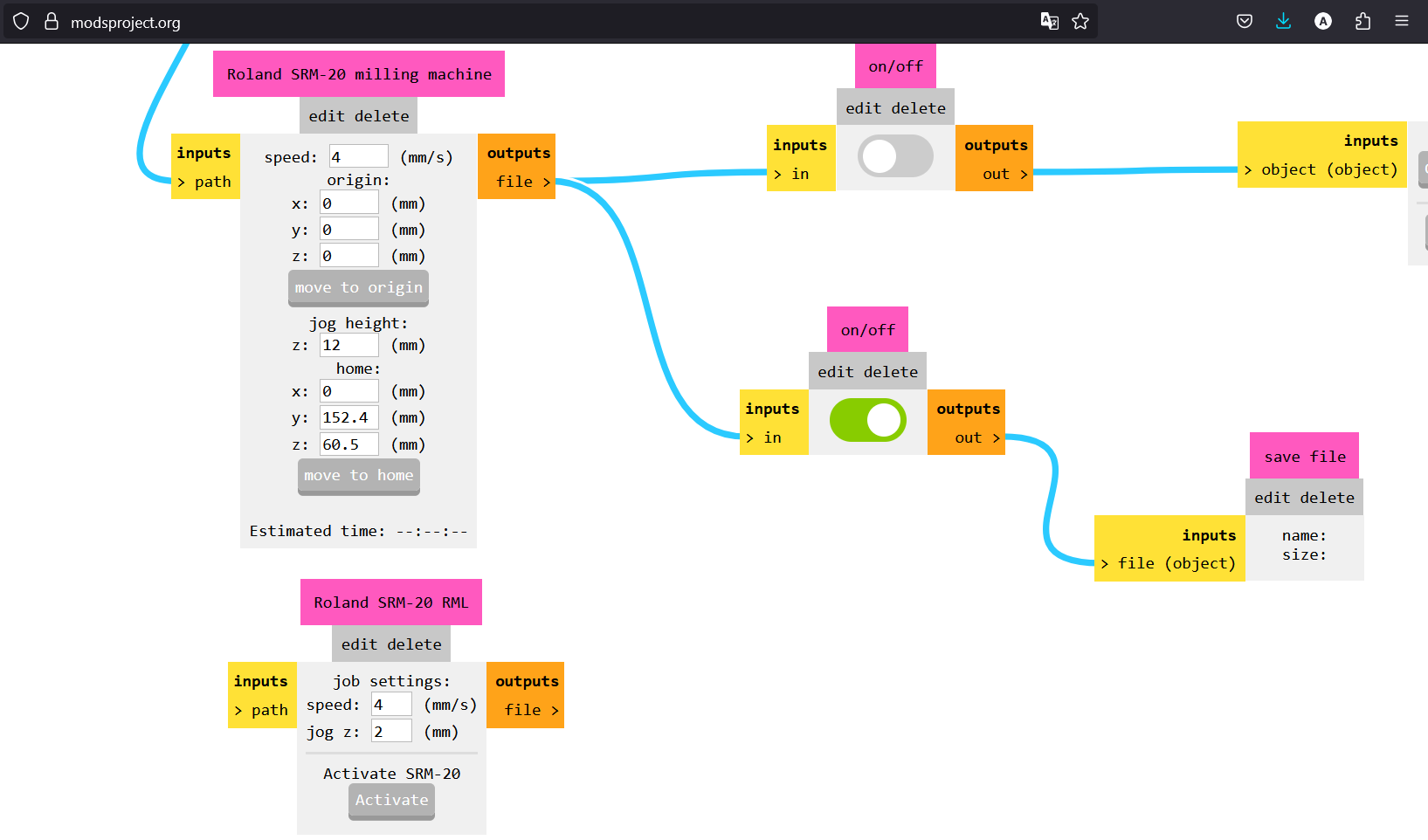
Step 4: Go to the File menu, locate SRM-20 mill, and click on Mill 2D PCB
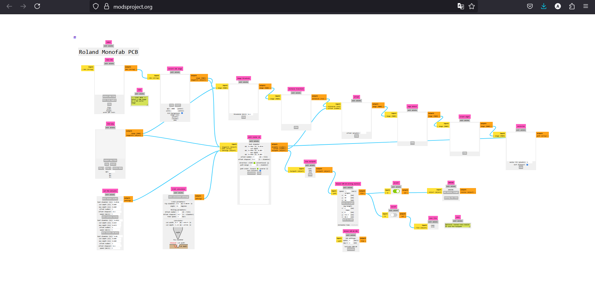
Step 5: The process flow diagram will open
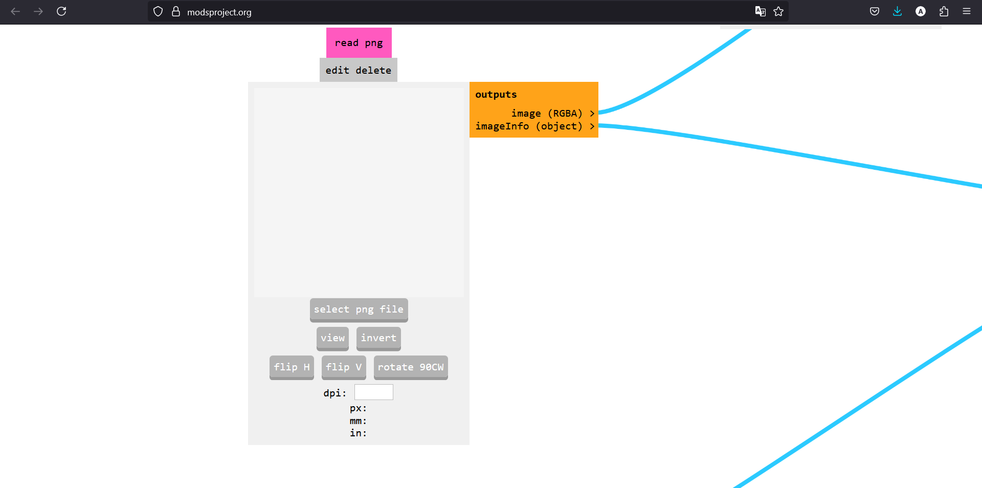
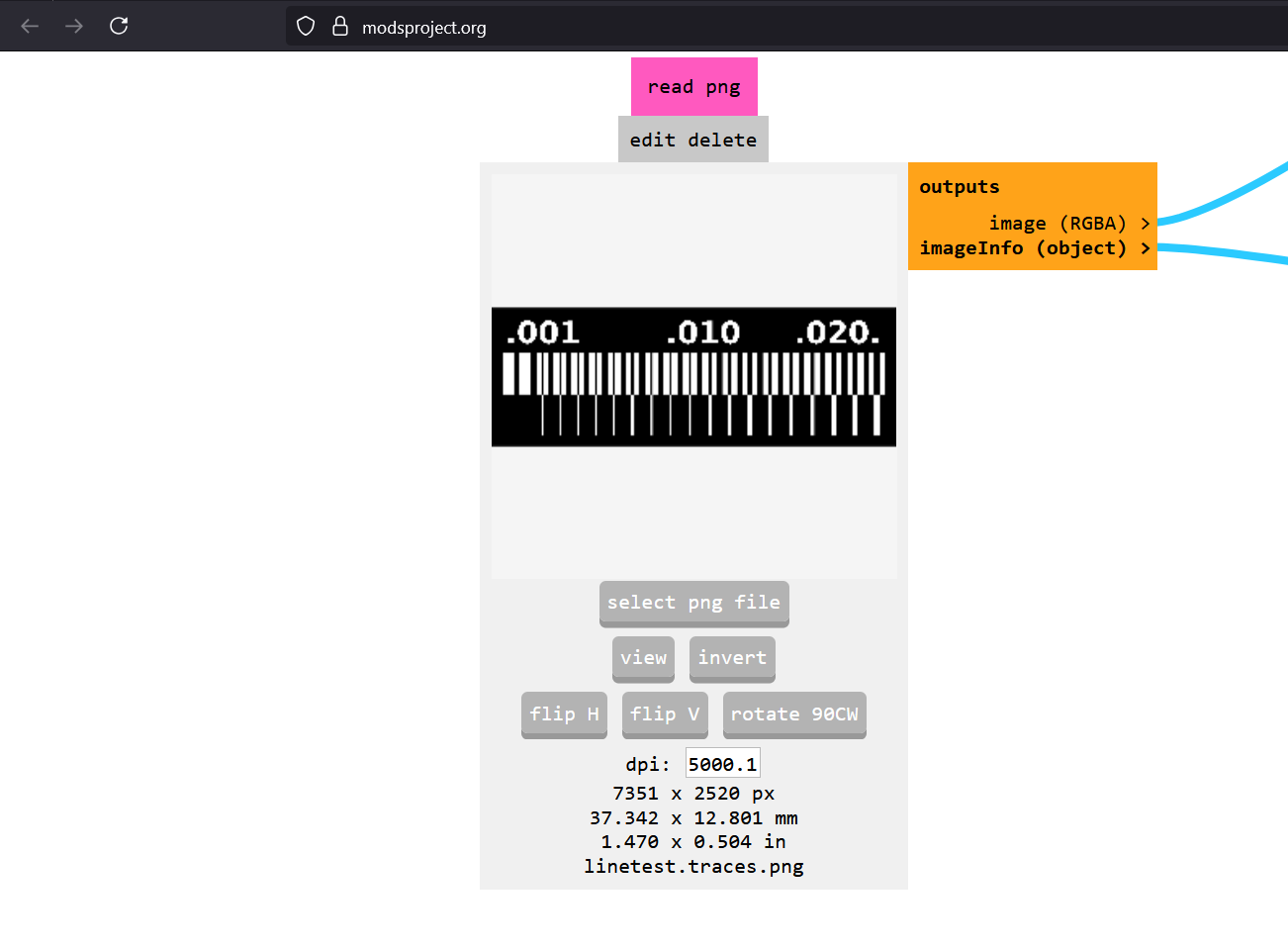
Step 6: Load the PCB PNG file by clicking "select png file"
Step 7: The file will be visible on the interface
Step 8: Set the XYZ origin to 0, as the machine will be operated through V Panel software
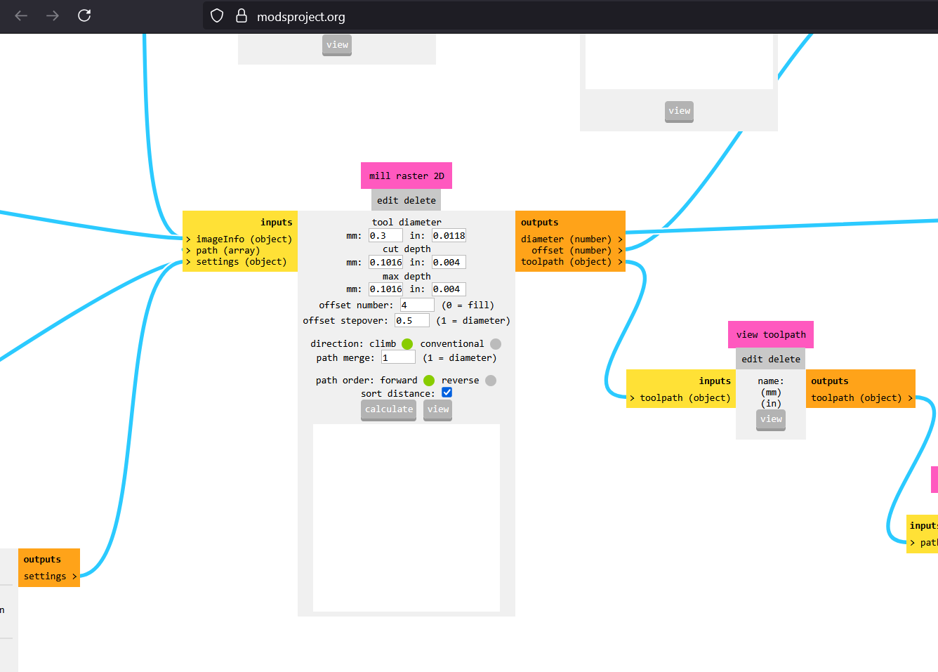
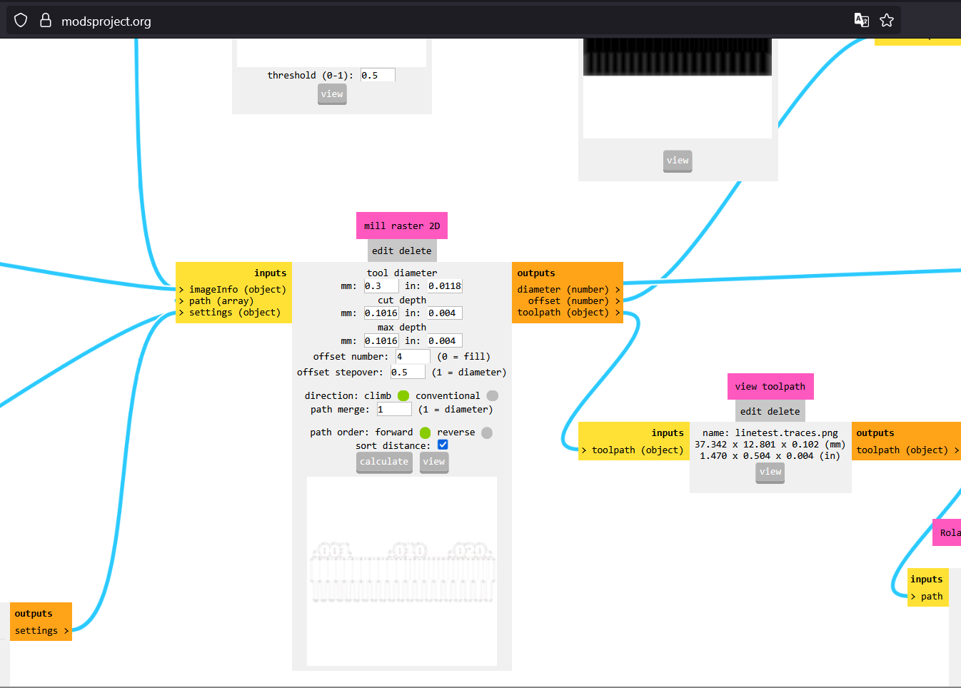
Step 9: After completing all settings, click Calculate to proceed
Step 10: The calculation process will begin
After these steps, an .rml file will be downloaded. This file contains the toolpath data required for the SRM-20 PCB milling machine to execute the cutting or engraving operation.
Material Fixturing
We used FR-1 (Copper Clad) PCB for tracing circuit paths during the milling process. FR-1 is a cost-effective, heat-resistant material commonly used for prototyping and single-layer PCBs. It provides good mechanical strength and electrical insulation, making it ideal for rapid PCB fabrication.
Applying double-sided tape to secure the FR-1 PCB to the milling machine
Properly applied tape with excess trimmed off
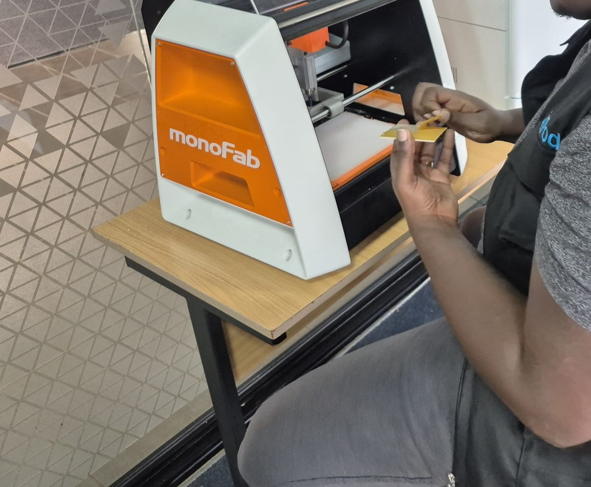
Placing the PCB in the milling machine and ensuring it is secure
PCB properly fitted in the milling machine's work area
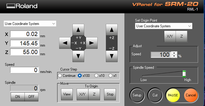
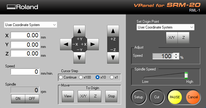
VPanel Software
VPanel (Virtual Panel) is the control software used for operating the Roland MonoFab SRM-20 CNC milling machine. It provides a user-friendly interface to manage and control the milling process.
Key Features
Machine Control: Allows users to move the spindle and set the origin
Speed Adjustment: Adjusts the rotation speed for different materials
Toolpath Execution: Loads and runs milling files (RML-1 format)
Job Monitoring: Displays real-time job progress and estimated completion time
Step 1: Open the V-Panel software
Step 2: The machine's XYZ origin has been successfully set
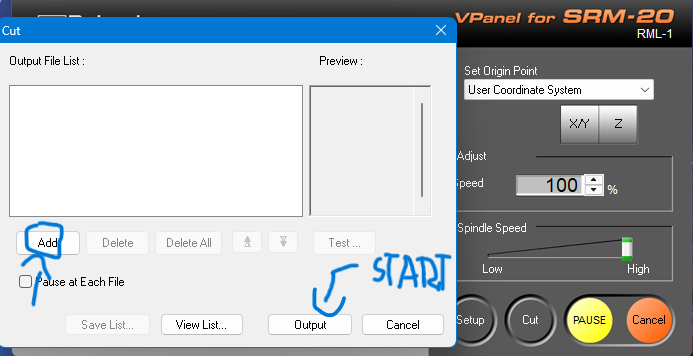
Step 3: Click on the Cut option and load the file and click on "Output" to start the cutting process/figcaption>