How I Created My Cat Face in GIMP
Hey everyone! I want to share how I made this cute cat face in GIMP. I'll walk you through my process and show you exactly what I did.
Getting Started
- First thing I did was to download the GIMP and Installed the app
- create a new file. I went to File > New to make a new canvas.
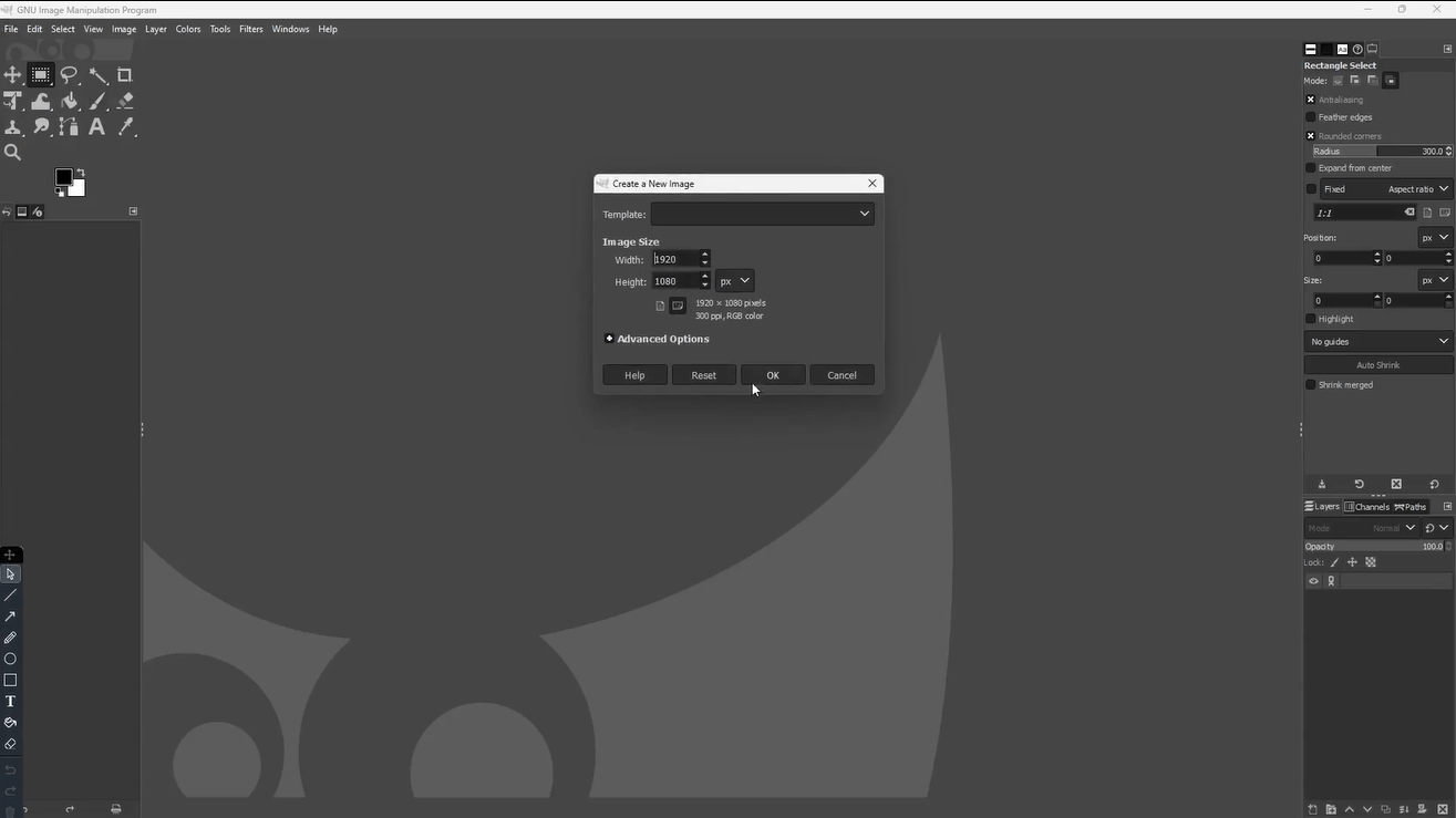
Setting up my canvas size - I used screen default because that's what I needed
I chose these settings:
- Width: 1920 pixels
- Height: 1080 pixels
- Resolution: 300 pixels/inch
Making the Face Shape
Okay, so for the main face, I started with the Rectangle Select Tool - you can find it on the toolbar or just press R.
The cool thing is, I discovered you can make rounded corners! I played with the settings at the bottom until I got the shape I wanted.
Look at those rounded corner settings
This is how my base shape looked - pretty basic!
Adding the Ears
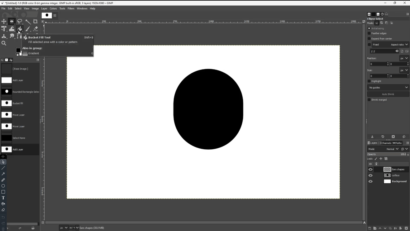
For the ears, I got creative with the Ellipse Select Tool (press E). I made two big circles at the top.
Making the ears was fun - I just drew two big circles
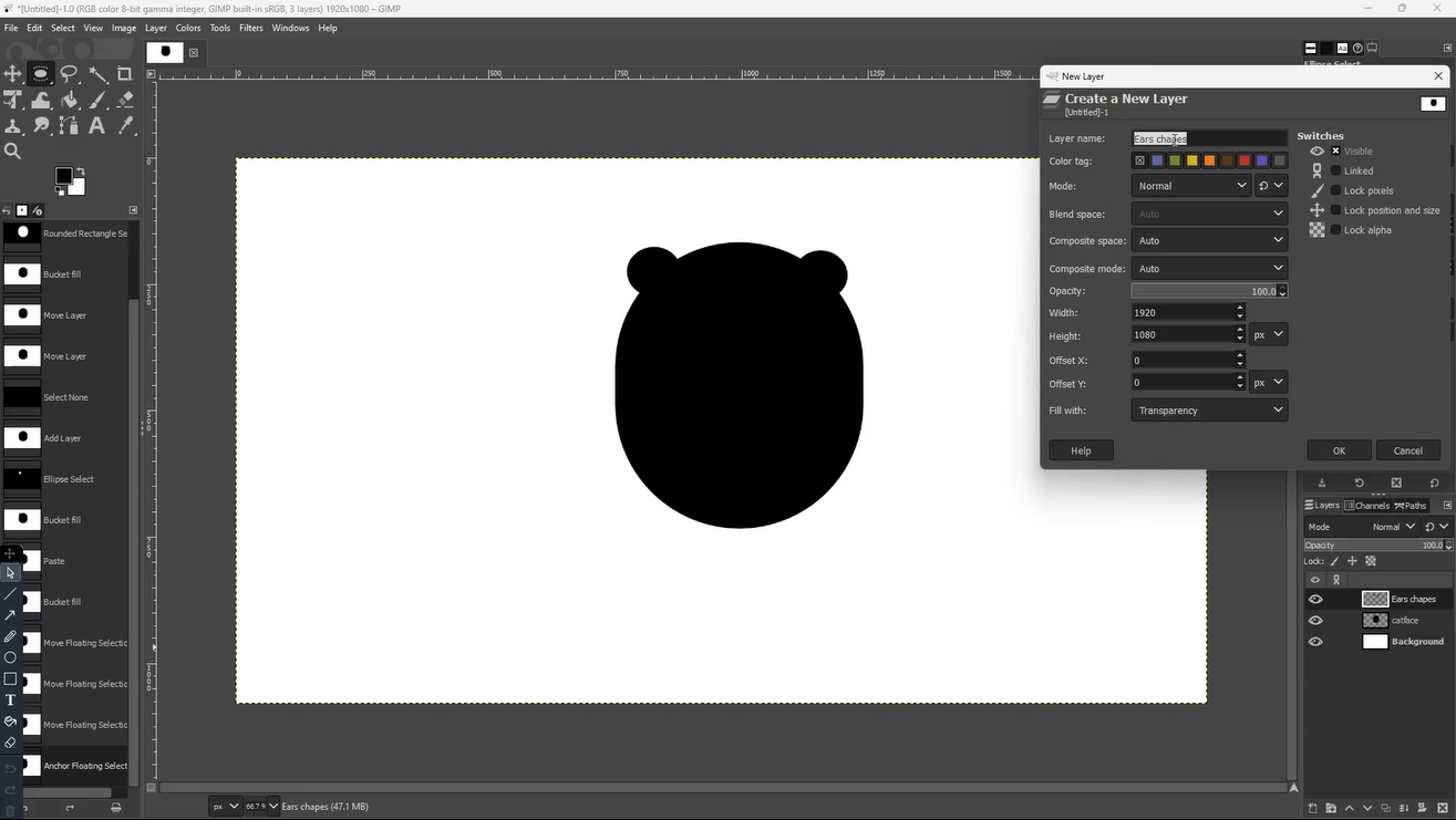
Creating the Eyes
The eyes were tricky! I made new layers for them (always use layers - learned that the hard way 😅).
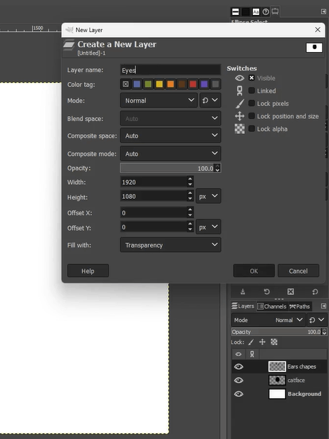
Keep your layers organized - it makes life so much easier!
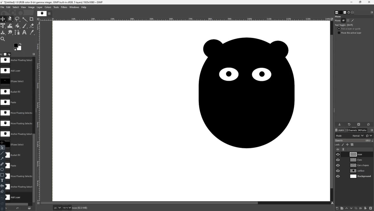
The eyes really started bringing the face to life
The Nose and Mouth
The nose was just a triangle with two circles for nostrils. I used the Paths Tool (B) for the triangle - it makes really clean lines!
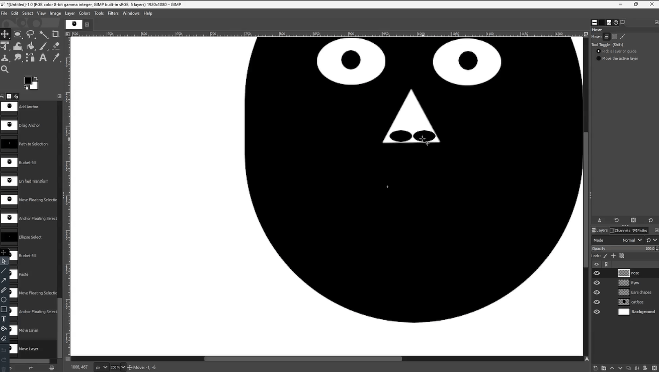
Making the nose - simple shapes can look really good together
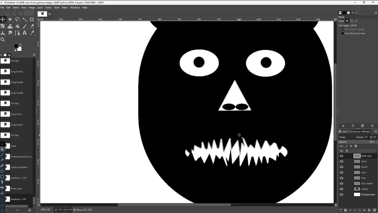
Creating all those curves and line for teeth took time but i learned the Basic
My finished cat face! What do you think?🙈
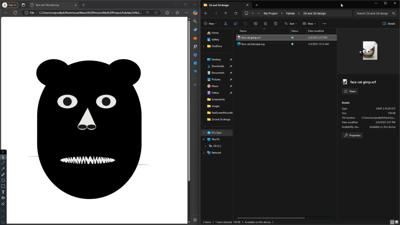
Files and Video of the all process
-
for the full video
- for orginal file face cat gimp.xcf
My First Steps with Inkscape: Creating again Cat Face
I'm just starting out with Inkscape,a choose the same simple cat face design.
Getting Started with Inkscape
I began by watching a basic tutorial about Inkscape youtube video. I picked this particular video because it covered the basics I needed for laser cutting.
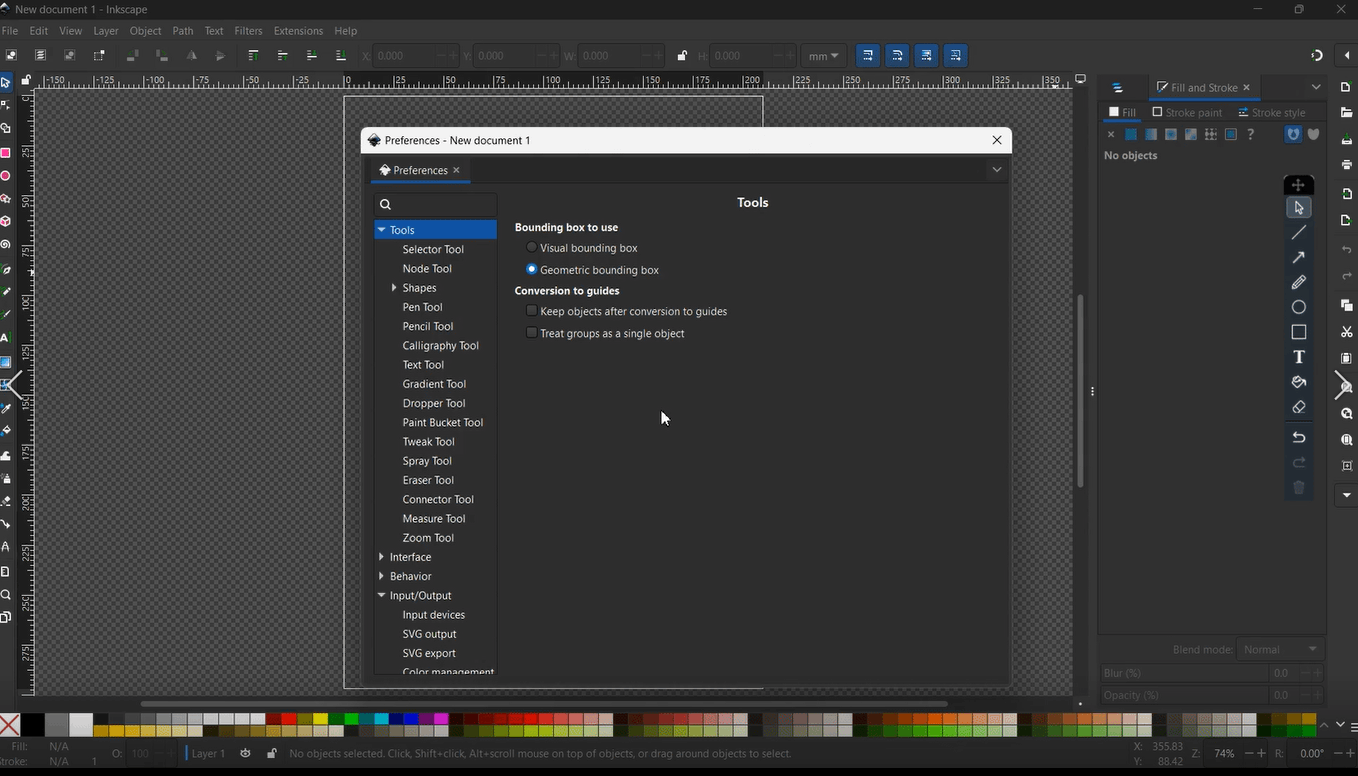
My Inkscape workspace setup
Starting with Basic Shapes
First, I drew a rectangle - nothing fancy, just a basic shape to start with. Then I thought, "Well, a cat needs ears!" so I added two circles at the top.
.png)
Starting with basic rectangle
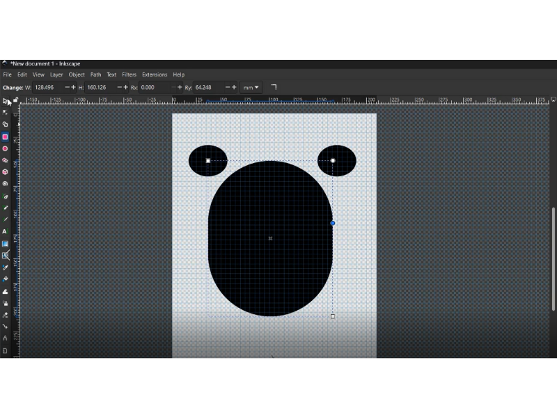
Starting with basic shapes for the face and ears
Making the Face Come Alive
The next part created rounded circle for the eyes, one rounded circle for the mounth and triangle for the nooze with a white color
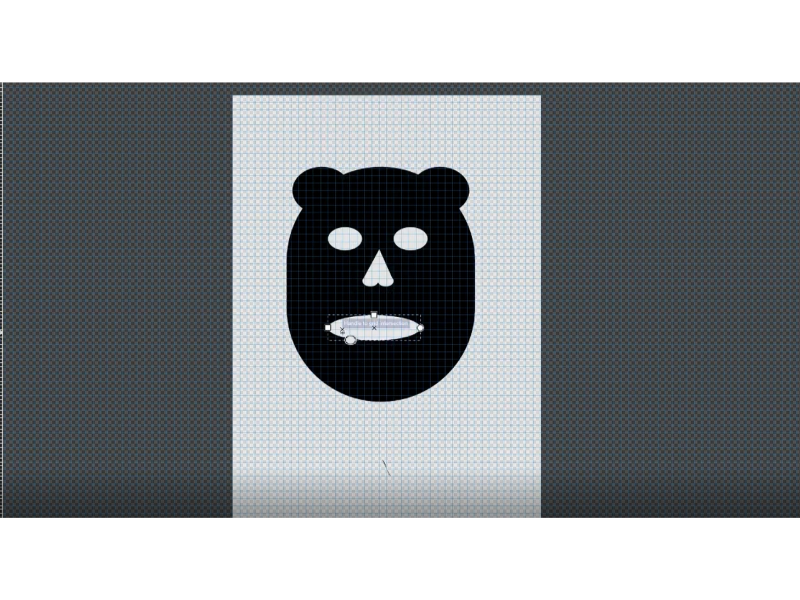
Adding the essential face details eyes, nooze and mouth
Adding two black circles for both eyes and noozes
Adding the essential face details eyes and nooze shape
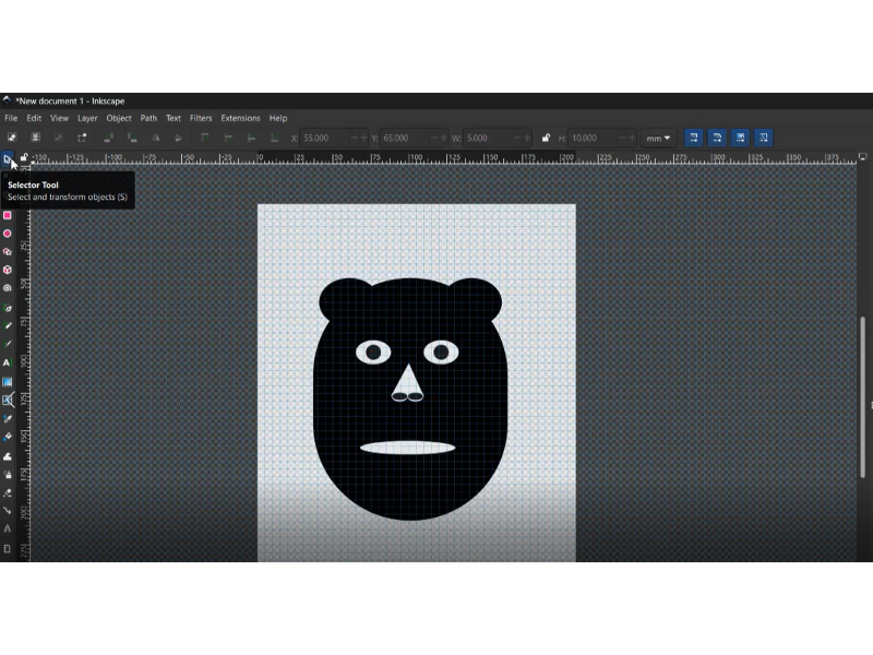
Adding the Final Details
The mouth was probably the trickiest part. I wanted to add some teeth to make it more interesting but is was easy that the GIMP.
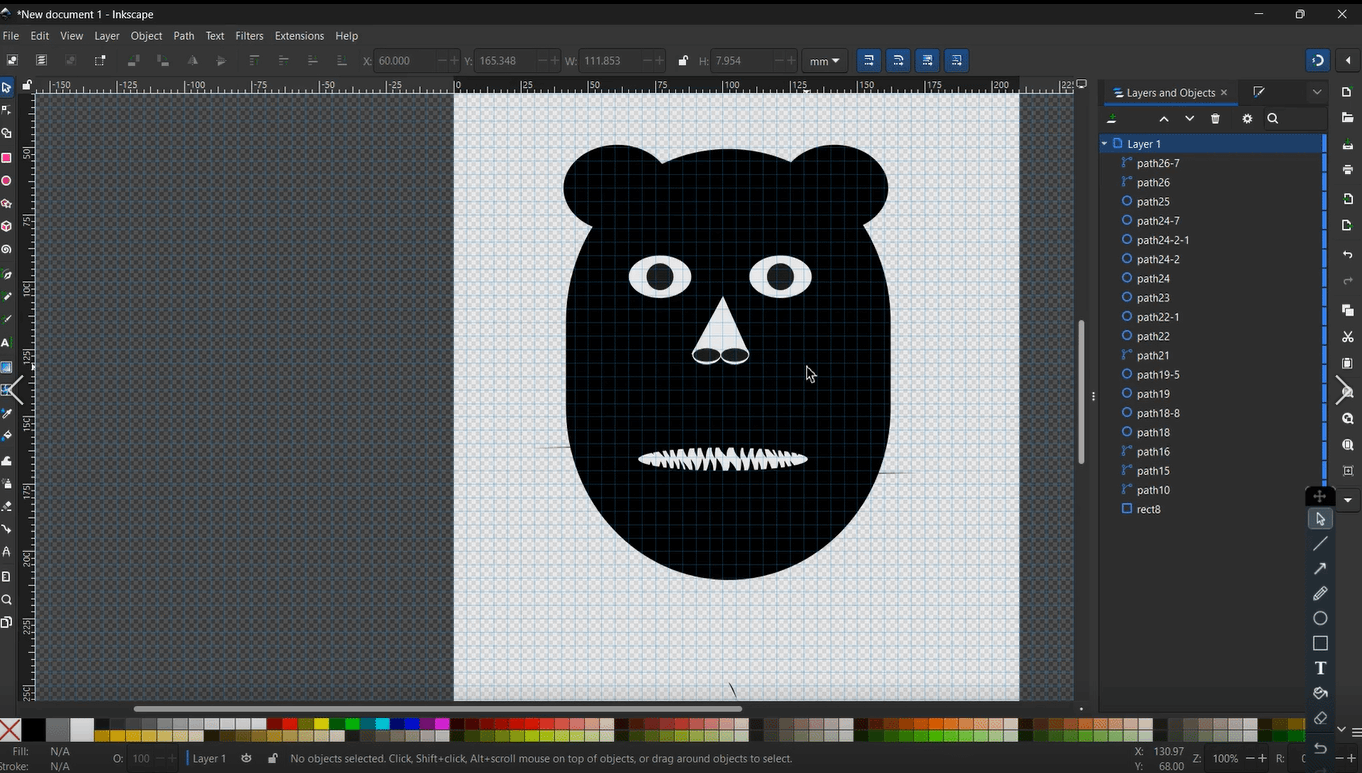
Creating the mouth with custom tooth shapes
What I Learned
Through this project, I figured out quite a few things about Inkscape:
- How to use the path tools to create and edit shapes
- Creating new files and setting up the document properties
- Working with millimeters (which is super important for laser cutting)
- Exporting my work
Files and Video of the all process
-
for the full video
- for orginal file face cat inkscape.svg
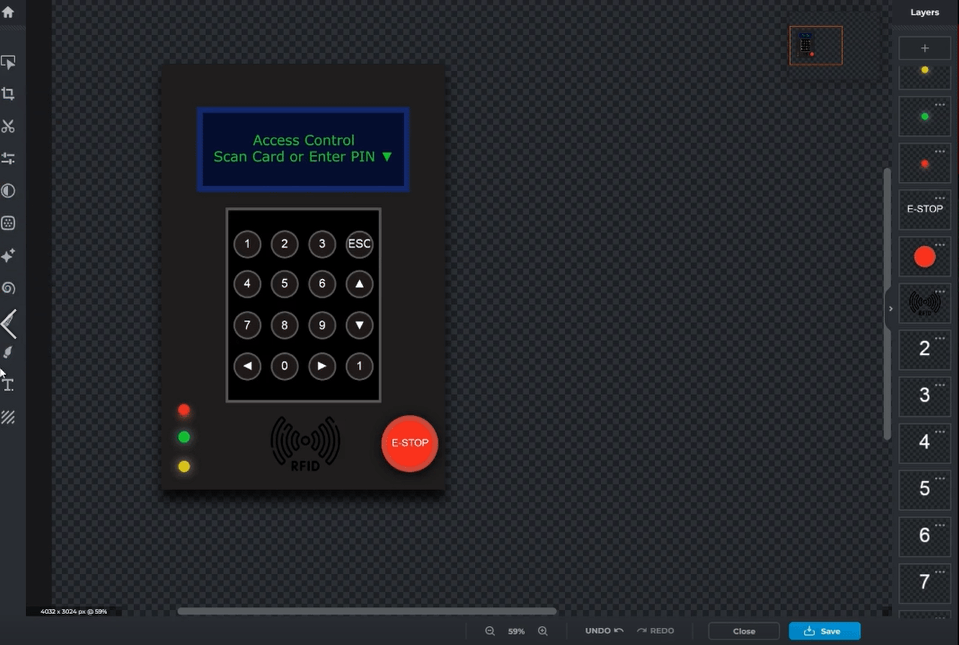
Creating My Project Mockup in Pixlr Express
Hey! Let me tell you about how I made my project Mockup using Pixlr Express.
I started by going to pixlr.com. I was already logged in from a previous project (can't quite remember what it was, but hey, it saved me some time!).
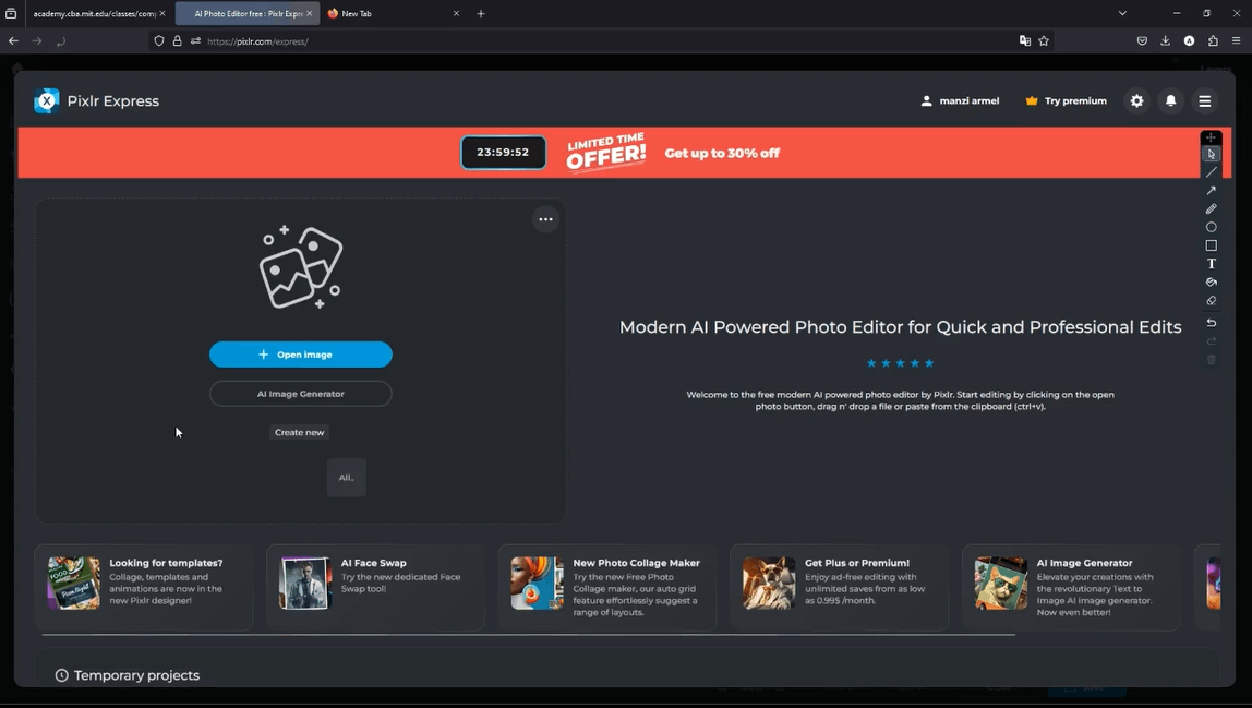
This is where it all started - the Pixlr Express main page
Creating the Base Layout
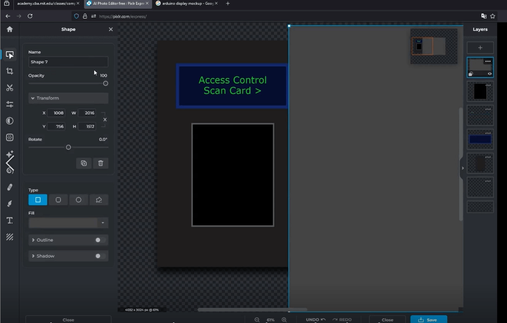
First thing I needed was a rectangle frame for my interface. I hunted around the tools until I found what I needed:
- Clicked on the rectangle frame tool
- Drew out the main shape for my project
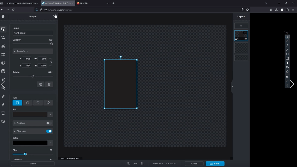
My first step - making the main frame
Adding the Display Screen
Next came the important part - the LCD display area. I did some research first to figure out what size would work best.
Adding the display - had to get the size just right
Making the Control Panel
Creating the Number Pad
I needed quite a few buttons:
- Numbers from 0-16
- Made them all the same size for consistency
- Arranged them in a grid
Setting up all those number buttons took some time!
Navigation Controls
Then I added the navigation buttons:
- Left arrow
- Right arrow
- Forward button
- Back button
- Yes button
- Cancel button
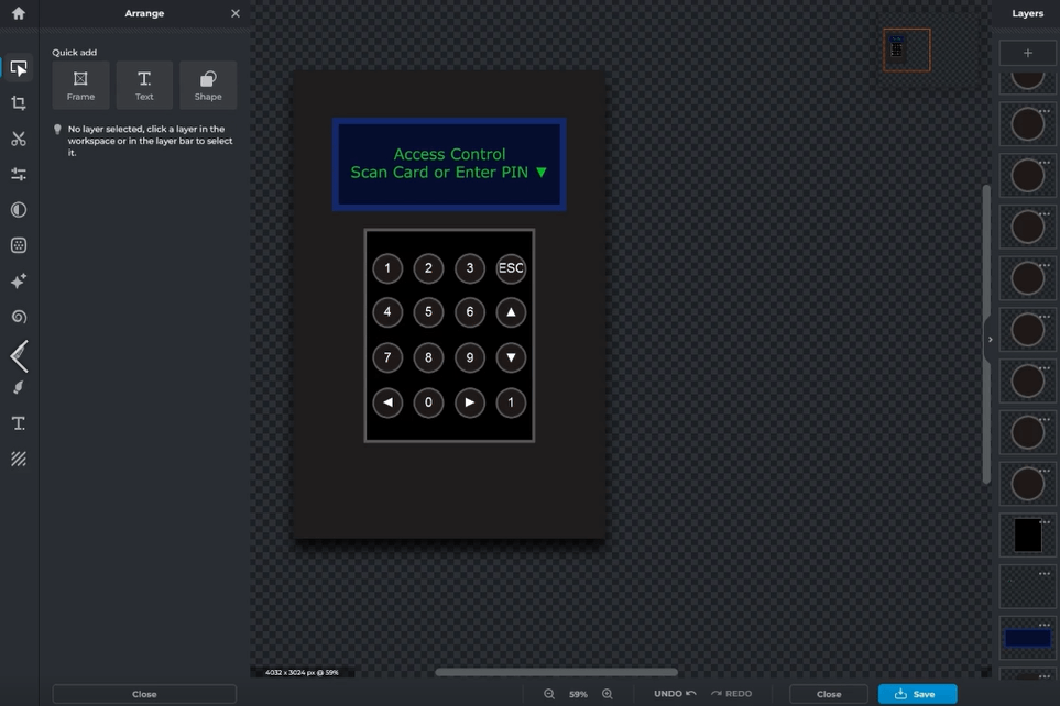
All the buttons that help you move around the interface
Adding Special Features
The Enter and Cancel Buttons
Made these stand out since they're important:
- Created the Enter button
- Added the Cancel button
- Made sure they were easy to spot
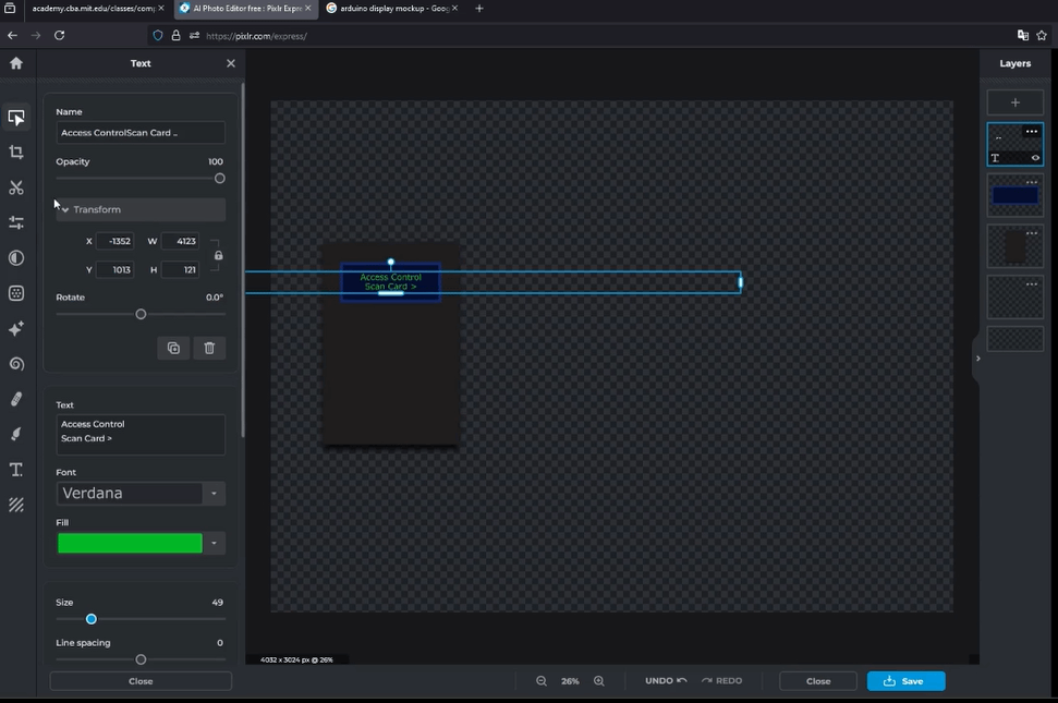
Adding Guide Markers
I wanted to add some helpful RFID hint, so I created what I call "stickers" - they show users where they should tap their card.
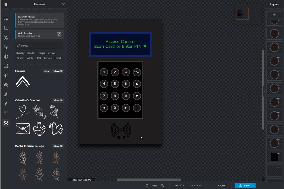
Little visual hints to help people use the card
Safety Features
Emergency Controls
Safety first! I added:
- An emergency stop button
- Made it really visible and easy to find
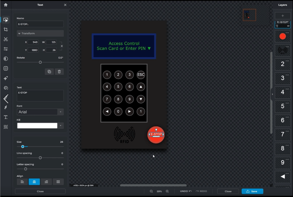
The emergency stop - super important!
Status Lights
Added some LED indicators to show:
- If there's a problem
- When everything's working fine
- Other important status info
These lights help you know what's going on
Finishing Up
The last thing I did was name it "MakerGate" - straight to the point!
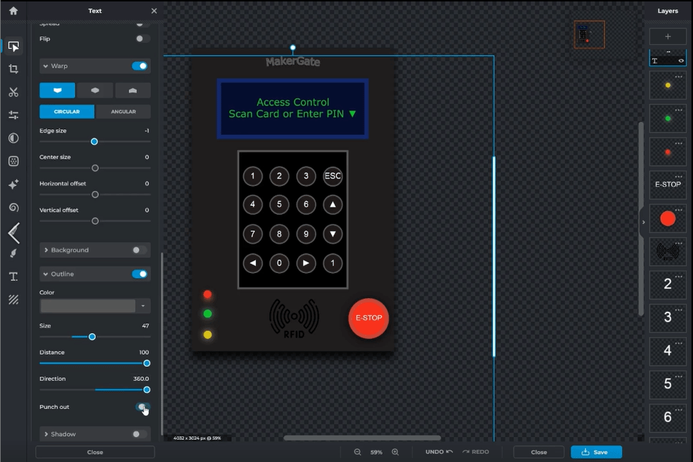
The finished product - pretty happy with how it turned out!
Files and Video of the all process
-
for the full video
- for orginal file Project Mocup Pixrl.pxz
Creating My project Cover in FreeCAD: My 3D Modeling Journey
Getting Started with Research
Hey everyone! I started by watching a YouTube tutorial about creating a box in FreeCAD youtube video - it wasn't exactly what I wanted to make, but it had a lot of similar techniques I could use.
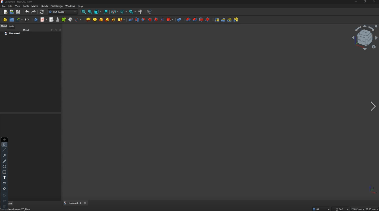
This is where my journey started - the FreeCAD workspace
Creating the Basic Shape
First, after creating the Box body, I jumped into the sketching area and created a rectangle that matched my mockup's dimensions.
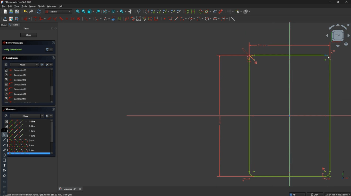
Starting with a simple rectangle - sometimes the simplest starts are the best!
Moving to Part Design
After getting my basic shape, I switched over to Part Design. This is where things got interesting:
- Used the padding tool to give my shape some depth
- Made it 100 millimeters thick to fit all my components
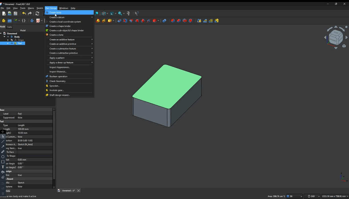
Making that flat shape into a 3D box - pretty cool to see it come to life!
Adding Screw Holes
Next came the important part - adding holes for the screws:
- Created circular pads for each screw location
- Made sure they were properly aligned
- Saved this as my front body - super important for later!
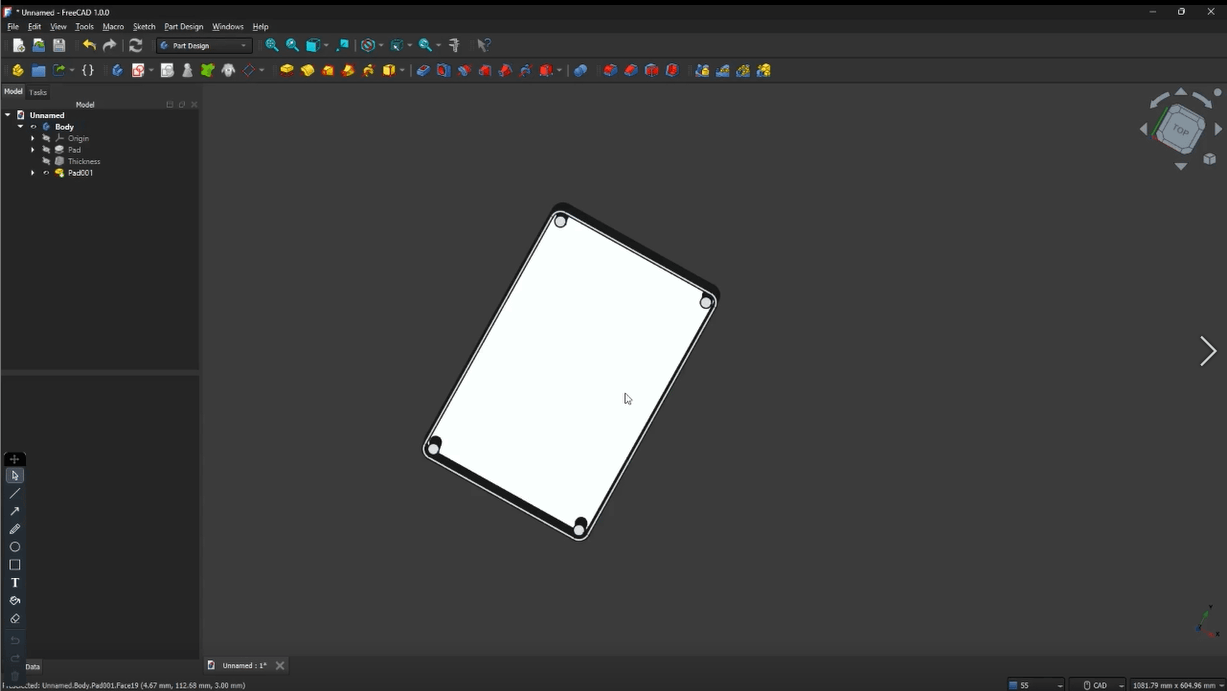
Adding those screw holes took some careful measuring
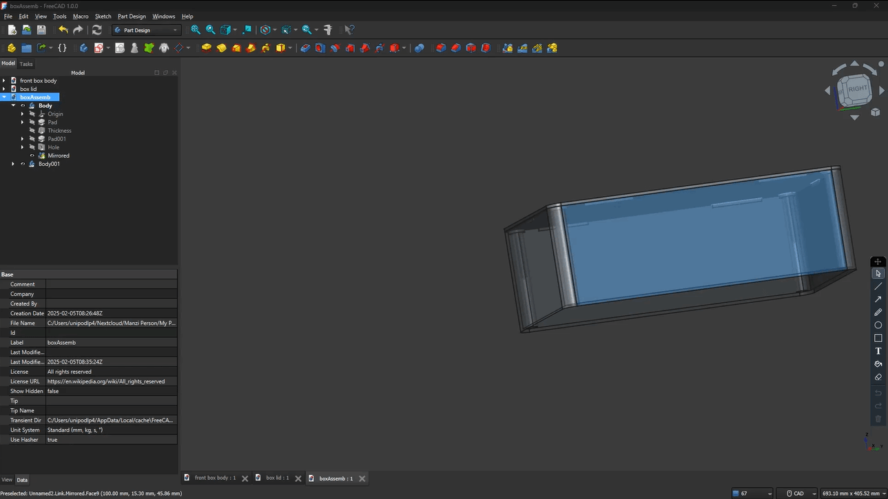
Creating the Back Cover
Here's where it got interesting:
- Created another body for the back cover
- Used the front body as a reference
- Added matching screw holes
- Included stands for the cover to rest on
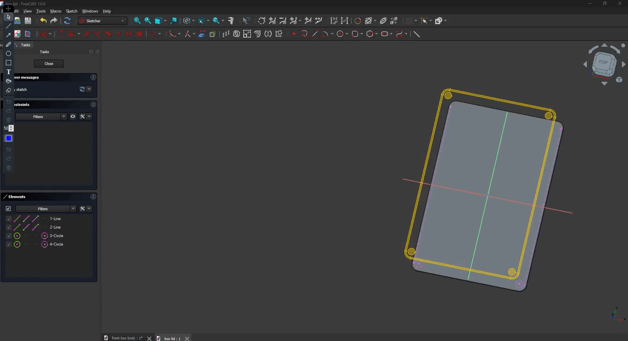
Making the back cover to match the front
Using the Mirror Tool
This was a cool trick I learned:
- Used the mirror tool to copy the details to the other side
- Saved me tons of time not having to redo everything
- Made sure everything lined up perfectly
The mirror tool was like magic - copy once, use twice!
Connecting the Parts
The final step was connecting everything:
- Created a new body to join the front and back
- Used the Makerlink tool in FreeCAD
- Made sure everything fit together properly
Bringing all the pieces together - this was satisfying!
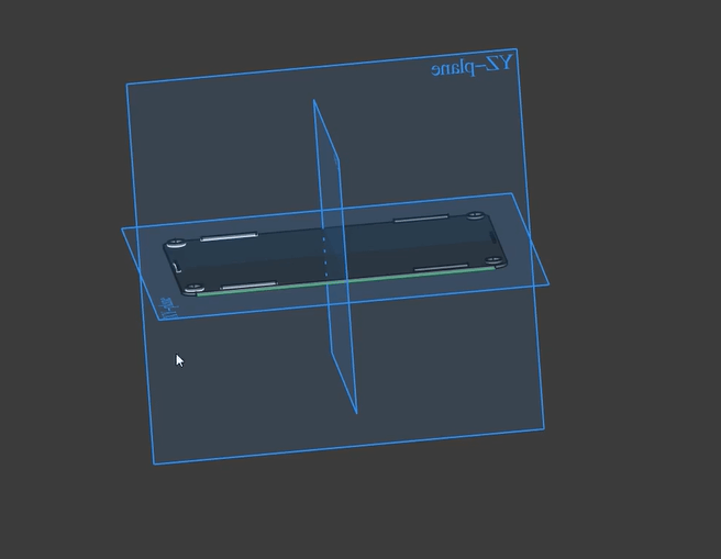
Planning Component Layout
Last but not least:
- Made a sketch showing where all components would go
- Helped me make sure everything would fit
- Gave me a good reference for assembly later
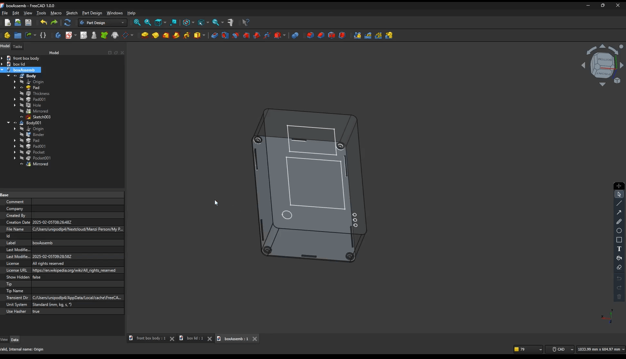
Planning where everything goes - measure twice, cut once!
What I Learned
This project taught me a lot about:
- Working with multiple bodies in FreeCAD
- Using the mirror tool effectively
- Planning ahead for component space
- Making sure parts align correctly
Creating a Quick Return Mechanism in OnShape
I started by ready the Resources Shared by Luciana on the email and by watching a YouTube tutorial that shows how to create one youtube video
Signup with the fablab provided account from the email
-
Opening the invite link:
- signup just the same email and the password
- then login
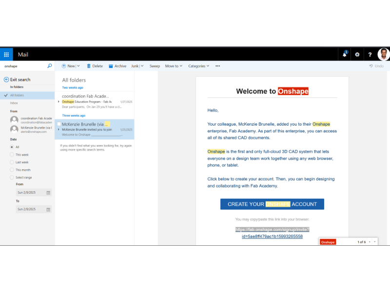
email sent by fablab
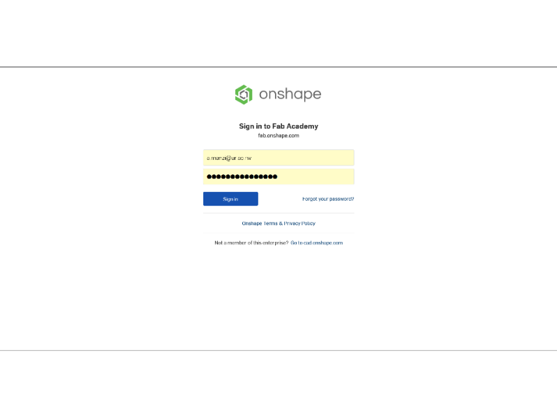
login page
Getting the Initial Setup Just Right
how I set up my workspace in OnShape:
-
Opening the right workspace:
- Clicked on "Part Studio"
- Selected the right plane (this is super important!)
- Used 'N' key for normal view
- Used 'P' to hide planes (makes it much cleaner)
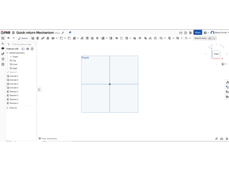
the part studio starting point.
The Base Rectangle (Super Important!)
This part needs to be perfect because everything builds on it:
-
Starting the center point rectangle:
- Pressed 'S' for sketch
- Clicked exactly on the origin point
- Dragged out while holding Shift to keep it level
-
Made sure to use these exact measurements:
- Width: 122mm (this is crucial!)
- Height: 12mm
- Double-checked that it was centered on origin
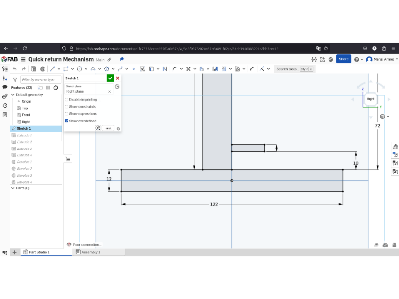
the part studio starting point.
The Vertical Structure (This Was Tricky)
Here's exactly how I made the vertical part work:
-
Creating the two-point rectangle:
- Started from the midpoint of the base
-
Used these measurements:
- Width: 16mm
- Height: 166mm
- Important tip: Make sure it's perfectly vertical!
- Used the midpoint constraint to keep it centered
-
Adding constraints:
- Used vertical constraint tool
- Checked alignment with base
- Made sure everything was fully defined
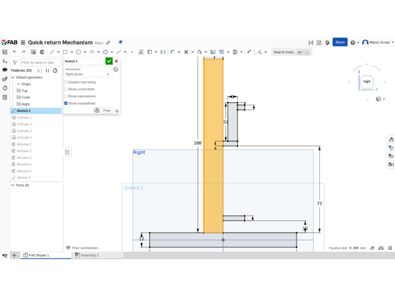
the part studio starting point.
The Tricky Pivot Points
This part was challenging, so here's exactly what I did:
-
First pivot:
- Made it 4mm vertical dimension
- Positioned exactly 10mm from bottom
- Used construction lines for alignment
- Added midpoint constraint
-
Second pivot (wheel and pin):
- Set width to 32mm exactly
- Height: 8mm
- Critical 2mm distance from edge
- Added the 4mm pin
- Vertical distance: 72mm (super important!)
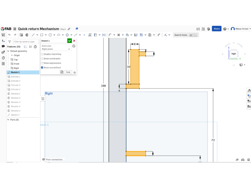
the part studio starting point.
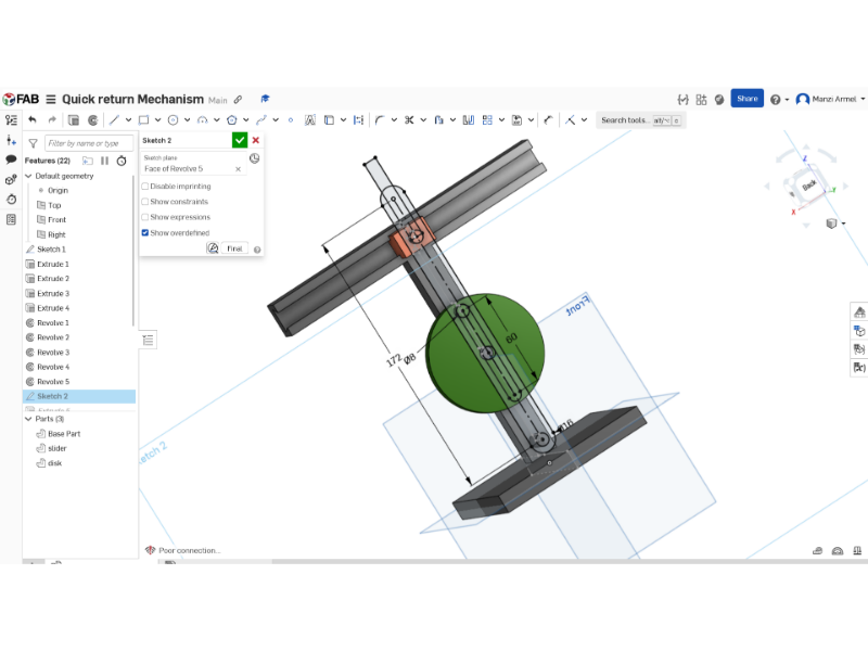
The Complex Dovetail Slider (Step by Step)
This was probably the trickiest part. Here's my exact process:
-
Starting the rectangles:
-
First rectangle:
- Width: 16mm
- Height: 12mm
-
Second rectangle:
- Pin size: 4mm
- Distance: 6mm
-
First rectangle:
-
Critical alignments:
- Used vertical constraints
- Added midpoint relations
- Made sure everything was symmetric
- Created construction lines for guidance
-
The dovetail angle (this is crucial):
- Pressed 'LQ' for construction line
- Set exact 8mm distance
- Made precisely 18-degree angle
- Used horizontal constraint ('H' key)
- Mirrored across centerline
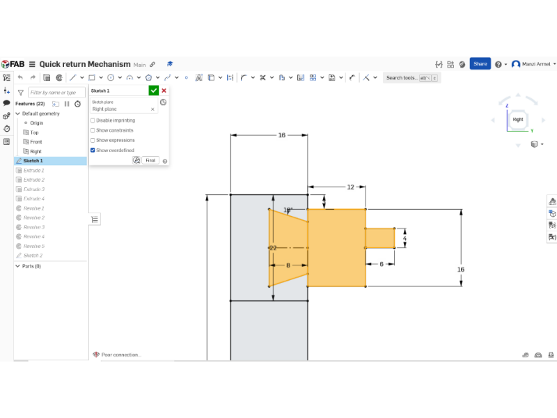
the part studio starting point.
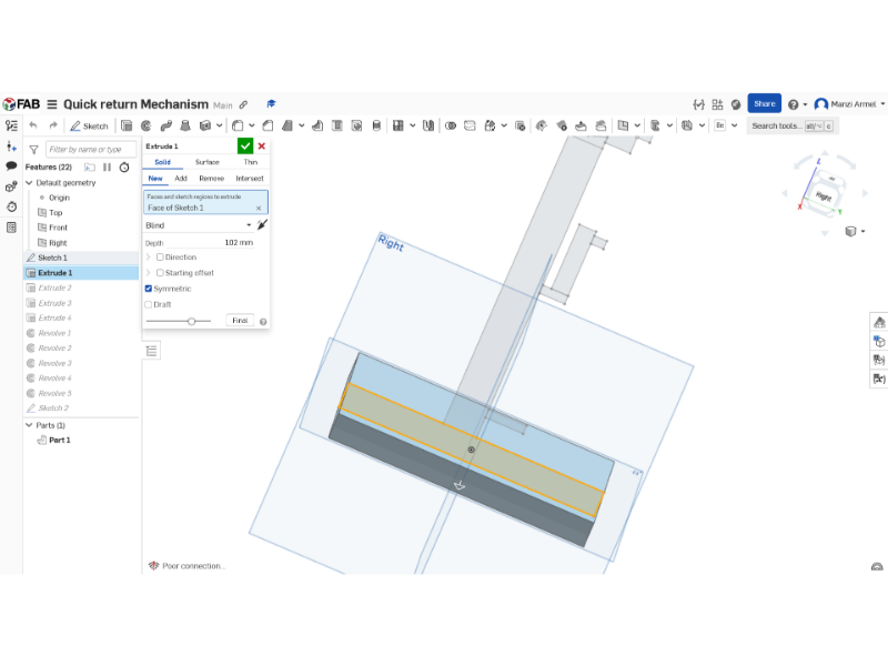
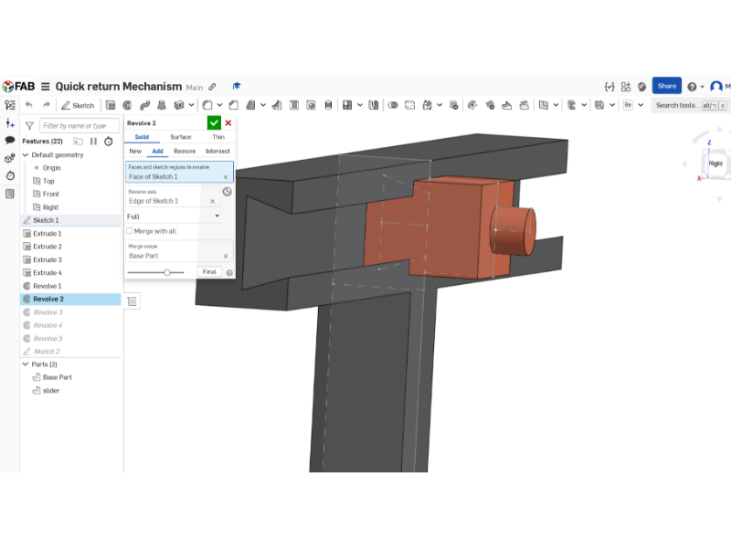
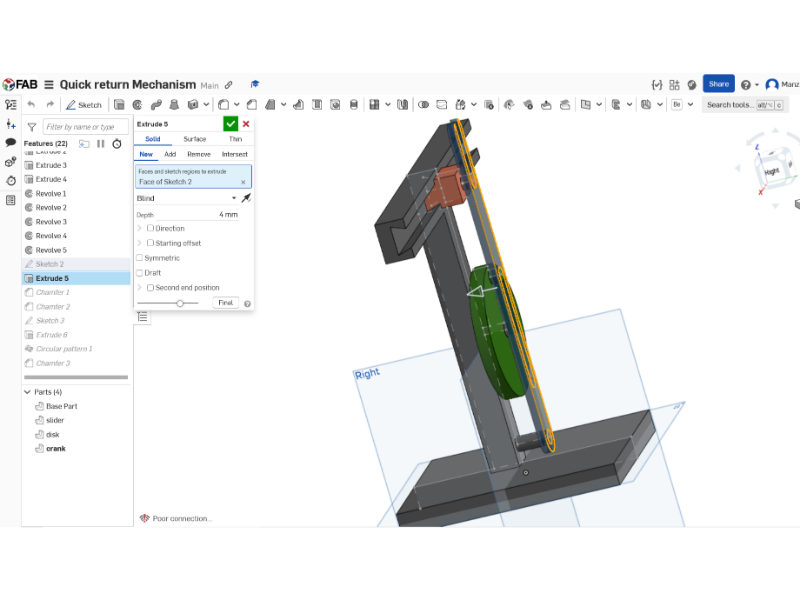
The 3D Transformation
Here's exactly how I turned it into 3D:
-
First extrude the base rectangle:
- Selected base plate
- Used symmetric extrude
- Depth: 102mm exactly
- Kept sketch visible (this helps!)
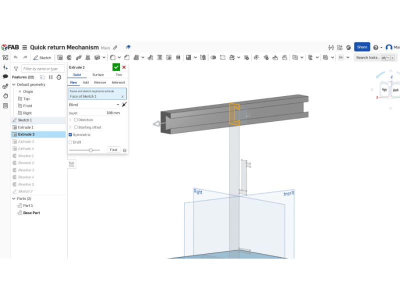
-
Second extrude:
- 188mm symmetric
- Made sure to select right faces
- Checked alignment
-
Final extrude:
- 18mm symmetric
- Added to both parts
- Double-checked connections
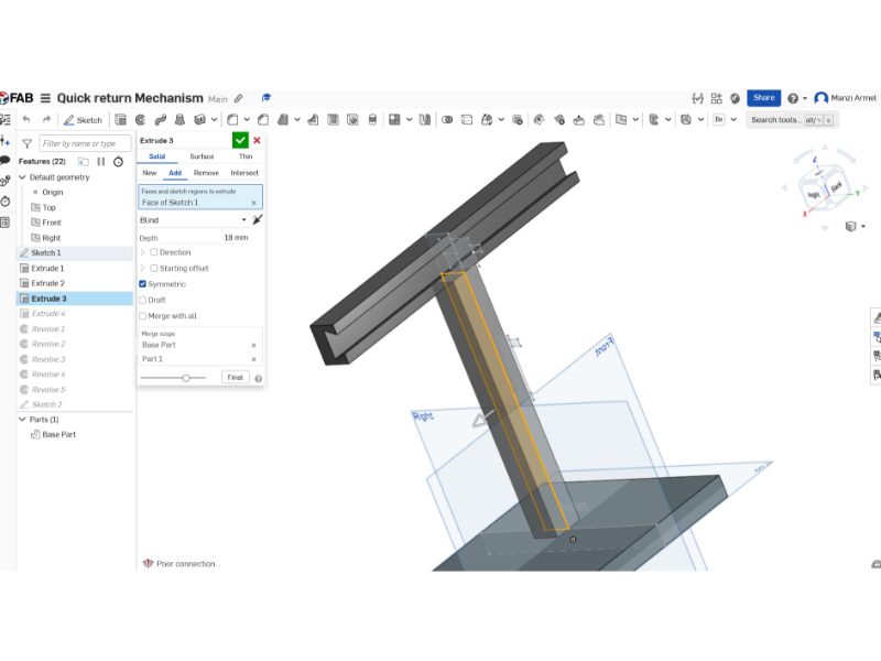
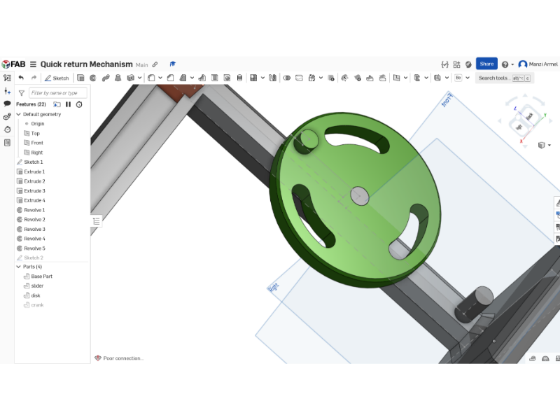
the crack sketch2.
the crack ectruded and well aligned.
The Assembly Process (Making It All Work)
This part needs extra attention:
-
Revolute mates:
- Selected cylindrical faces first
- Made sure rotation axis aligned
- Double-checked freedom of movement
-
Slider mates:
- Selected right faces
- Aligned Z-axis properly
- Tested movement before continuing
-
Tangent mates (this was tricky):
- Turned off tangent propagation
- Selected curved faces carefully
- Checked motion after each mate
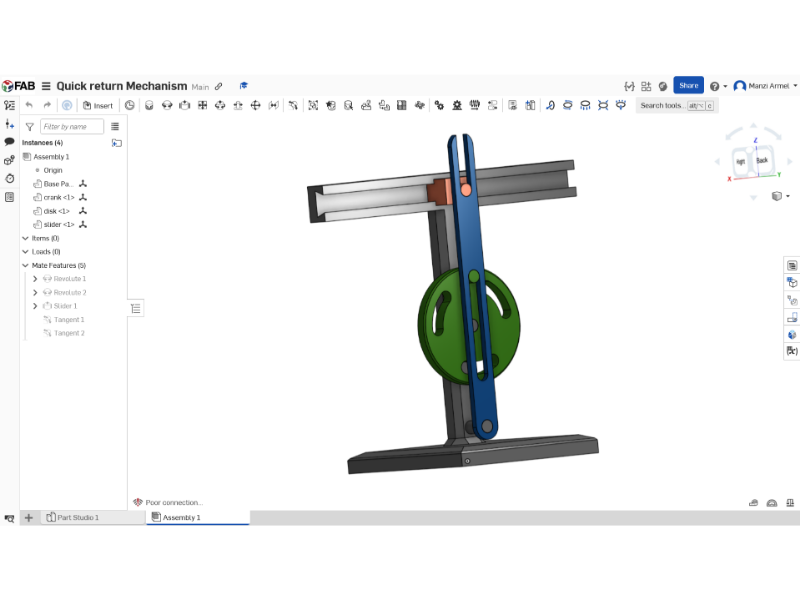
the final Assembly.
Click Here to view the project on ONSHAPETesting and Troubleshooting
Here's what to check if things aren't moving right:
- All pivot points should rotate freely
- Slider should move smoothly
- No binding in the mechanism
- All mates properly constrained
- and the similation is working
Extra Tips I Learned
-
For precise sketching:
- Use construction lines liberally
- Double-check all constraints
- Look for the blue (fully defined) color
-
For 3D features:
- Build symmetrically when possible
- Check relations before accepting
- Use the rollback bar to fix mistakes
-
For assembly:
- Test motion frequently
- Use mate connectors for complex alignments
- Keep track of degrees of freedom