Personal Reflection: What I Learned Group assignment
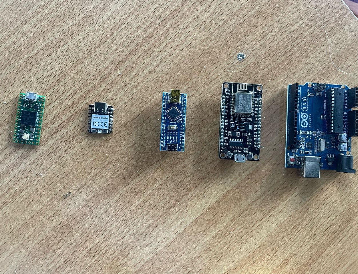
Working with different microcontroller platforms during this assignment was an eye-opening experience. The hands-on comparison between Arduino, ESP8266, Xiao RP2040, and Teensy 4.0 helped me understand the practical differences between these platforms beyond just technical specifications.
I was particularly surprised by how each board excels in different scenarios. While Arduino provided a gentle introduction to embedded programming with its straightforward IDE and extensive community support, I found the ESP8266's built-in WiFi capabilities fascinating for IoT applications.
For My person assigment i choose to work with the ESP32-DevKitC V4.
The Basics:
so all you need to get started is:
- The ESP32-DevKitC V4 board
- USB cable (it's micro USB B)
- My computer
Looking at the board itself:
There are different versions depending on what you need: Can come with different ESP32 modules (like WROOM-32, WROVER, etc.)
- Choice of male or female pins
The Important Parts:
Main Components:
- ESP32-WROOM-32 (that's the brain)
-
Two buttons:
- EN (that's the reset)
- Boot (for uploading code)
- USB port for power and programming
- LED to show when power's on
- Lots of I/O pins on both sides
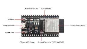
Here's what all the important parts look like
Something Important I Noticed:
- Some pins (D0, D1, D2, D3, CMD, CLK) are used by the board itself
- Found out GPIO16 and 17 only work on some versions
- Had to be careful about power - can only use one power source at a time
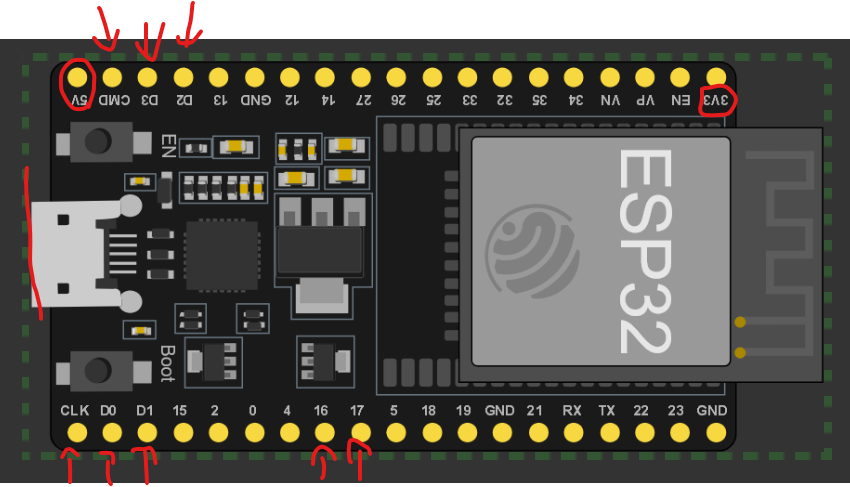
Watch out for these special pins!
Power Options:
- USB port (that's what I'm using)
- Can use the 5V and GND pins
- Or the 3.3V and GND pins
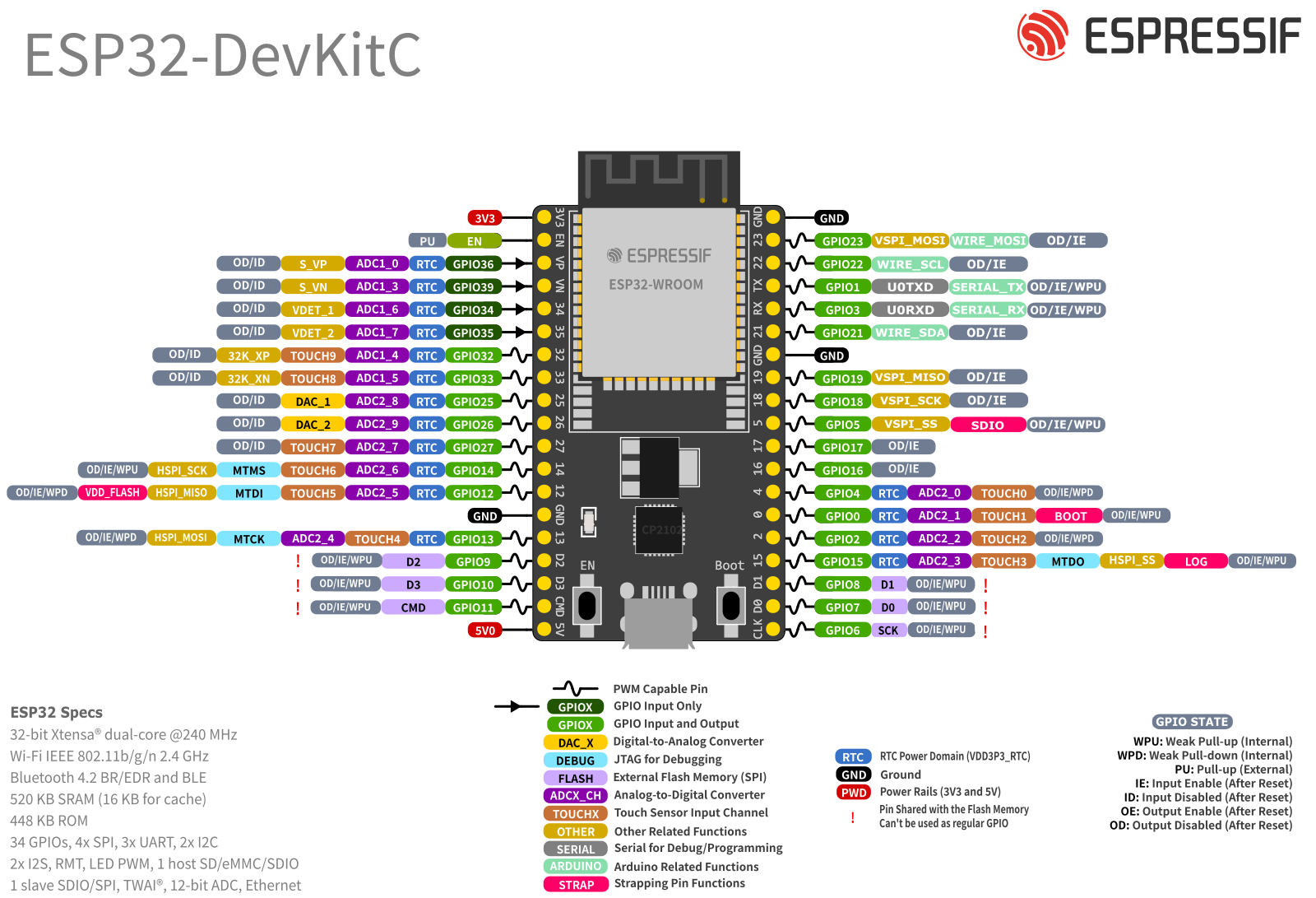
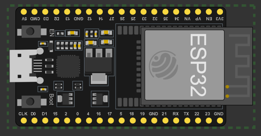
here is the pinlayout for the ESP32 devkic v4
There's this thing about a component called C15 that can cause some issues:
- Might make the board boot into download mode
- Can mess with GPIO0 if you're using it for clock
- Solution: just remove it if you have problems
Setting Up Wokwi Simulator with PlatformIO in Visual Studio Code and start Desing my project MakerGate
WHY using VSCODE: I started by using the online version of the wokwi.com but i always had error when trying to compile so i dicided to follow the sugestion
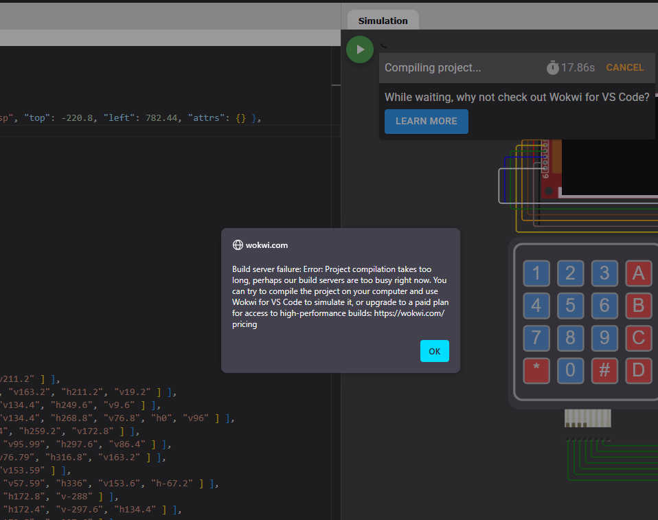
this the error
then i decided to go through the process of setting up Wokwi simulator with PlatformIO in VS Code for my embedded system project as recommand by wokwi. I learned along the way.
Prerequisites
- Visual Studio Code installed on your system (I used the latest version)
- PlatformIO extension installed in VS Code
- Basic understanding of embedded systems and Arduino framework (don't worry if you're just starting)
- Wokwi account (I started with the free tier)
1. Initial Setup
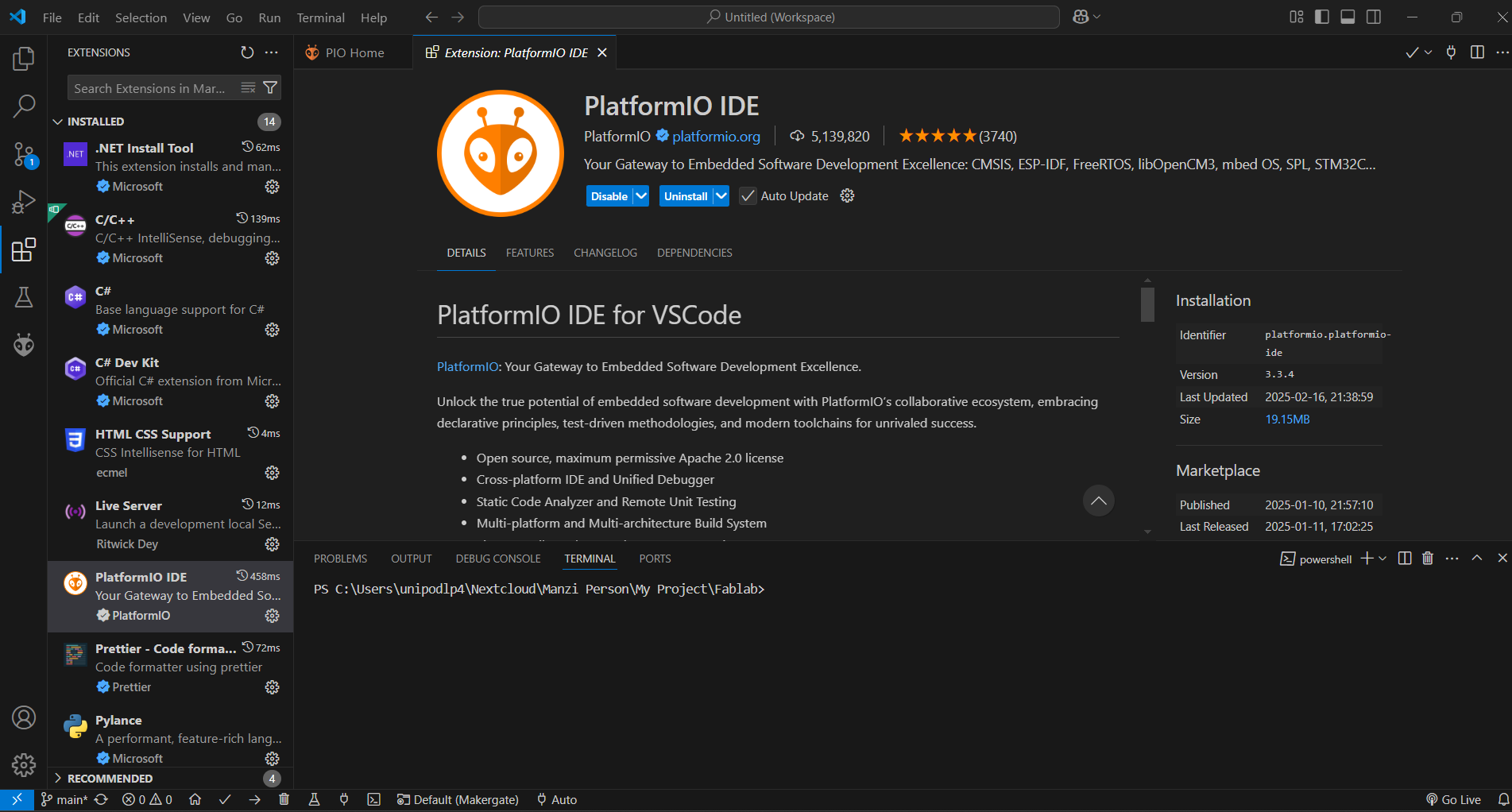
Here's how the PlatformIO extension looked in my VS Code
- First, I opened up Visual Studio Code
- Used the shortcut Ctrl+Shift+X to get to the Extensions view
- Typed in "PlatformIO IDE" in the search bar
- Found and installed the PlatformIO extension
- Had to restart VS Code after installation (don't skip this step like I did initially!)
2. Creating a New PlatformIO Project
Setting up my first PlatformIO project was pretty straightforward
- I clicked on the PlatformIO icon in the left sidebar to open PlatformIO Home
- Found and clicked the "New Project" button
-
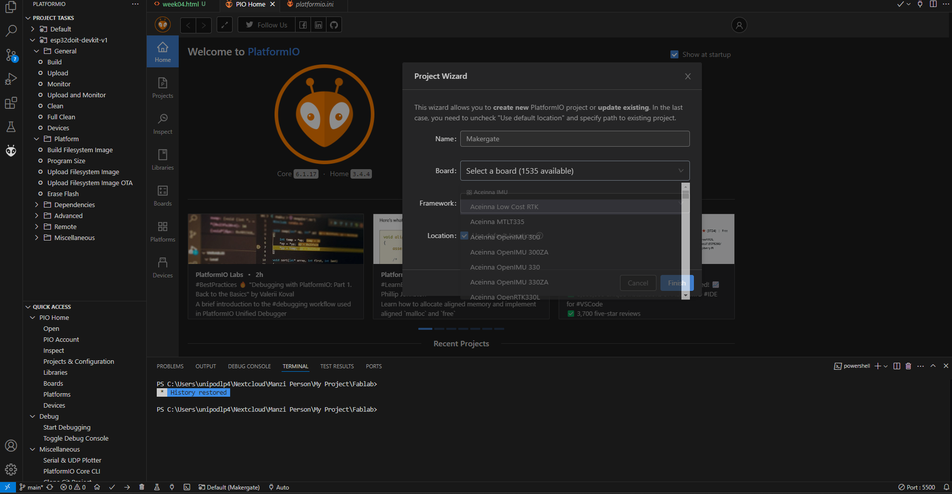
Here's how I configured my project settings:
- Gave it a meaningful project name
- Selected my board (I went with Arduino Uno for my first try)
- Chose Arduino as the framework
- Picked a convenient location directory
- Hit "Finish" and waited for the magic to happen
3. Setting Up Wokwi for Simulation
Setting up Wokwi Files
-
I created these essential files to the
PIO projectfolder:-
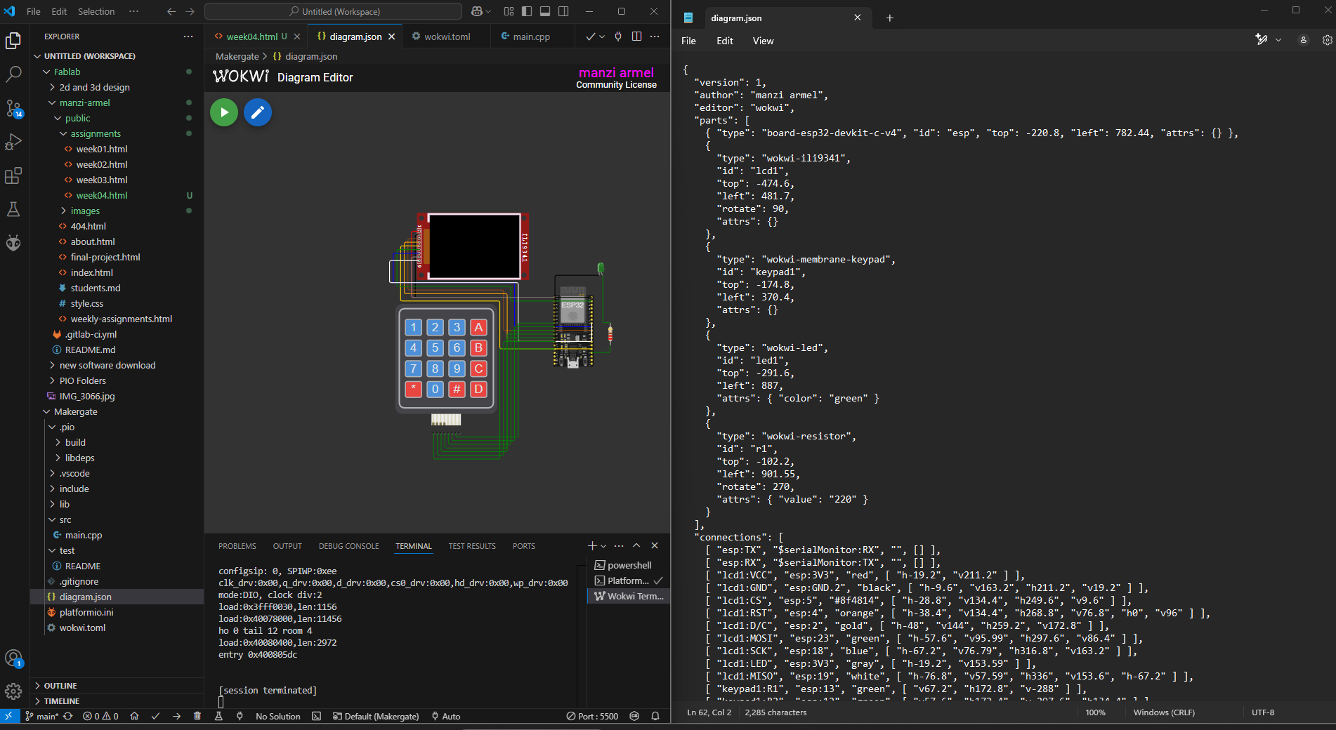
diagram.json- This is where your circuit configuration lives -
wokwi.toml- Contains all your simulation settings
-
- I clicked "Get your license key"
- Followed their activation steps
- Restarted VS Code to make sure everything took effect
you have to make sure that these files are in the same folder with your project all you will have the same issue
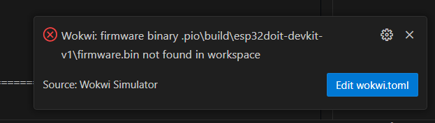
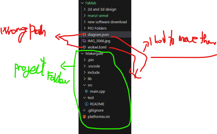
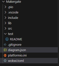
the error was that the wokwi could not locate the firmware files cause it was not in the same document with the pio project. to solve that i just moved the two file into the project folder
Example wokwi.toml Configuration
[wokwi]
firmware = ".pio/build/your_board/firmware.elf"
elf = ".pio/build/your_board/firmware.elf"
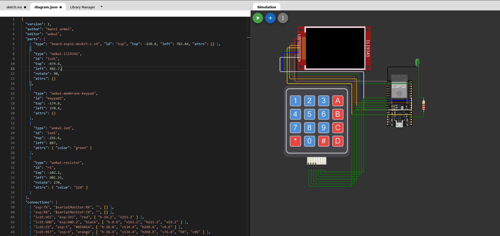
4. Configuring the Circuit (diagram.json)
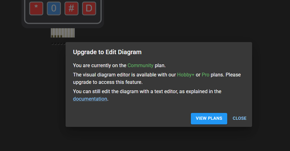
- I headed over to the Wokwi online simulator cause with a free account you can't edit inside the VScode (https://wokwi.com)
- designing my circuit in their simulator that is linked with my final project to see and understand the access control setup(it's actually pretty intuitive!)
-
then i copy my
diagram.jsoninto my vscode using the notepad cause you can't edit text using vscode with wokwi installed.
5. Writing and Compiling Code in c++
with the diagram connected i had to start coding
So, the system lets you enter a PIN code to get access - kind of like a digital lock! cause my project will need this concept of access control
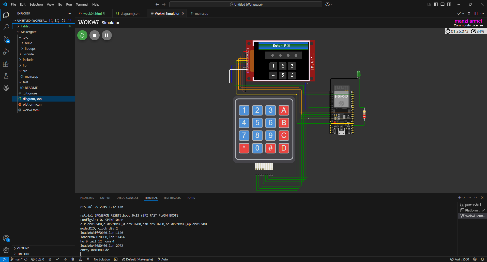
Here's how everything looks when it's set up!
The Cool Stuff It Does:
- Shows a nice PIN entry screen
- Lets you type in a 4-digit code
- Lights up when you get the right code
- Gives you visual feedback on the screen
What used as a Libraries:
First, make sure you've got these libraries installed:
- SPI.h (comes with ESP32)
- Adafruit_GFX.h (for the graphics)
- Adafruit_ILI9341.h (for the TFT screen)
- Keypad.h (for the keypad, obviously! 😄)
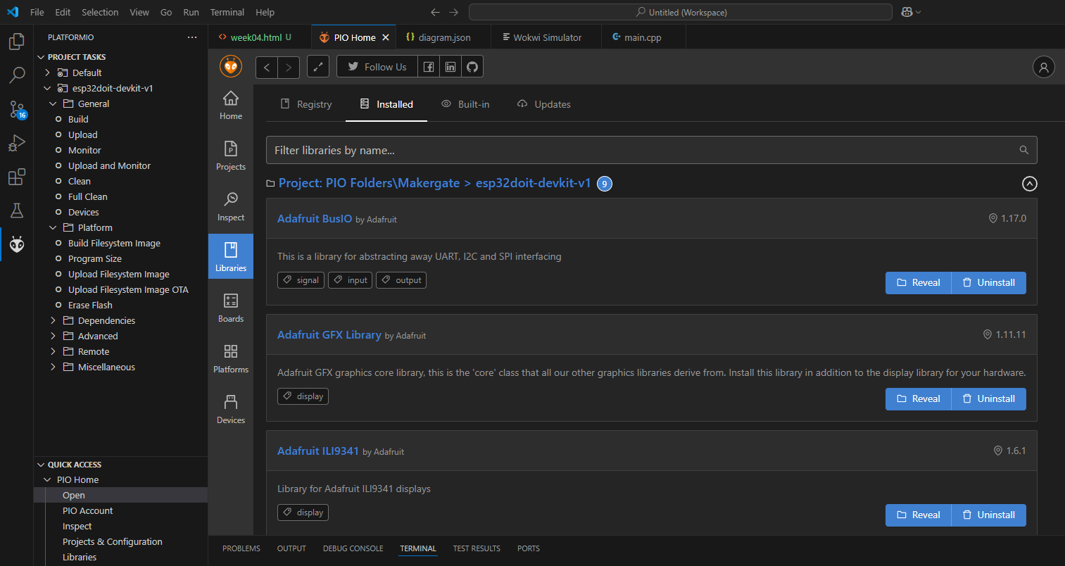
Here's where you can add the libraries to your project
Hooking Everything Up:
Here's how I connected everything:
TFT Screen and LED Pins:
#define TFT_DC   2
#define TFT_CS   5
#define TFT_MOSI 23
#define TFT_CLK  18
#define TFT_RST  4
#define TFT_MISO 19
LED Setup:
Super simple - just connect it to Pin 15!
#define LED_PIN 15
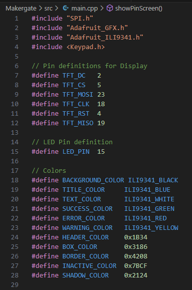
These pins are used to connect the TFT display and led to the ESP32 via SPI. plus the color Define
Keypad Connections:
byte rowPins[ROWS] = {13, 12, 14, 27}; // ROW: 1,2,3,4
byte colPins[COLS] = {26, 25, 33, 32}; // COL: 1,2,3,4
Constants and Variables i used
  #define BACKGROUND_COLOR ILI9341_BLACK
  #define TITLE_COLOR     ILI9341_BLUE
  #define TEXT_COLOR      ILI9341_WHITE
  #define SUCCESS_COLOR   ILI9341_GREEN
  #define ERROR_COLOR     ILI9341_RED
  #define WARNING_COLOR   ILI9341_YELLOW
  #define HEADER_COLOR    0x1B34
  #define BOX_COLOR       0x3186
  #define BORDER_COLOR    0x4208
  #define INACTIVE_COLOR  0x7BCF
  #define SHADOW_COLOR    0x2124
i set the Keypad Layout
  char hexaKeys[ROWS][COLS] = {
    {'1', '2', '3', 'A'},
    {'4', '5', '6', 'B'},
    {'7', '8', '9', 'C'},
    {'*', '0', '#', 'D'}
  };
PIN Handling
  const int PIN_LENGTH = 4;
  char currentPin[PIN_LENGTH + 1] = "";
  int pinIndex = 0;
  const char correctPin[] = "4444";
-
PIN_LENGTH: Length of the PIN (4 digits). -
currentPin: Stores the currently entered PIN. -
pinIndex: Tracks the number of digits entered. -
correctPin: The correct PIN for access.
Functions I used
showPinScreen()
-
Displays the PIN entry screen on the TFT display.
-
Turns off the LED.
-
Includes a header, PIN display area, and keypad layout.
showAccessGranted()
-
Displays a success message when the correct PIN is entered.
-
Turns on the LED.
-
Includes a progress bar animation.
updatePinDisplay()
-
Updates the TFT display to show the currently entered PIN as dots.
resetPin()
-
Resets the
currentPinandpinIndexvariables. -
Turns off the LED.
handlePinEntry(char key)
-
Handles keypad input:
-
Appends digits to
currentPin. -
Resets the PIN if
*is pressed. -
Validates the PIN if 4 digits are entered.
-
Calls
showAccessGranted()orshowPinScreen()based on the result.
-
setup()
-
Initializes the serial monitor, TFT display, and LED pin.
-
Displays the PIN entry screen.
loop()
-
Processes keypad input.
How It Works:
Here's the basic flow:
- Power it up, and you'll see the PIN entry screen
Enter the correct PIN (
4444) to grant access.The LED will turn on, and the TFT display will show a success message.
Enter an incorrect PIN to reset the input and display the PIN entry screen again.
Press
*to reset the PIN input.
6. Running the Simulation
Additional Resources That helped Me
- Official Wokwi Documentation: https://docs.wokwi.com (my go-to reference)
- PlatformIO Documentation: https://docs.platformio.org (super helpful for setup)
- Wokwi Online Simulator: https://wokwi.com (where I spent most of my time)