What I Had to Do This Week
Assignment: Design and document the system integration for my final project (and hope everything actually works together!)
Assignment: Design and document the system integration for my final project (and hope everything actually works together!)
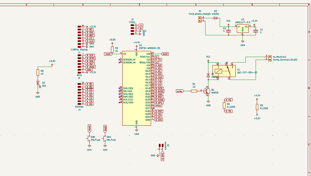
So MAKERGATE is basically my attempt to solve a real problem in our maker space - expensive tools going missing or getting damaged because anyone can just walk up and use them. My solution? Make them smart and secure! Here's how all the pieces work together:
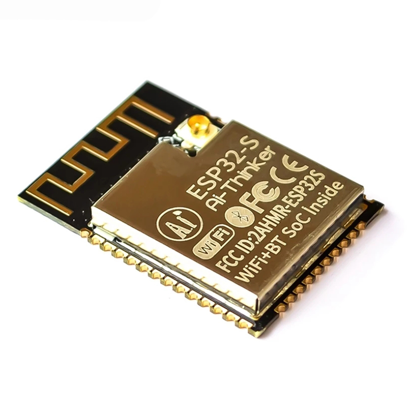
This is the brain of everything - controls all the other components
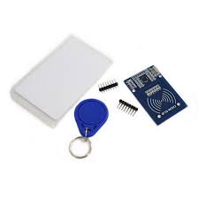
Reads user cards to identify who wants to use the equipment
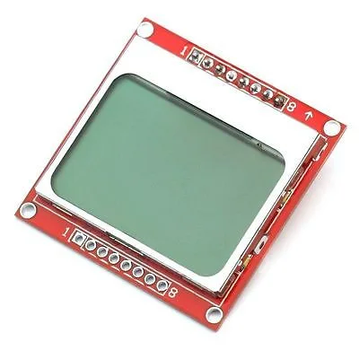
Shows status messages and user prompts
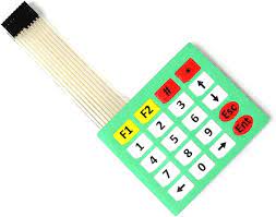
For entering PIN codes (because cards alone aren't secure enough)
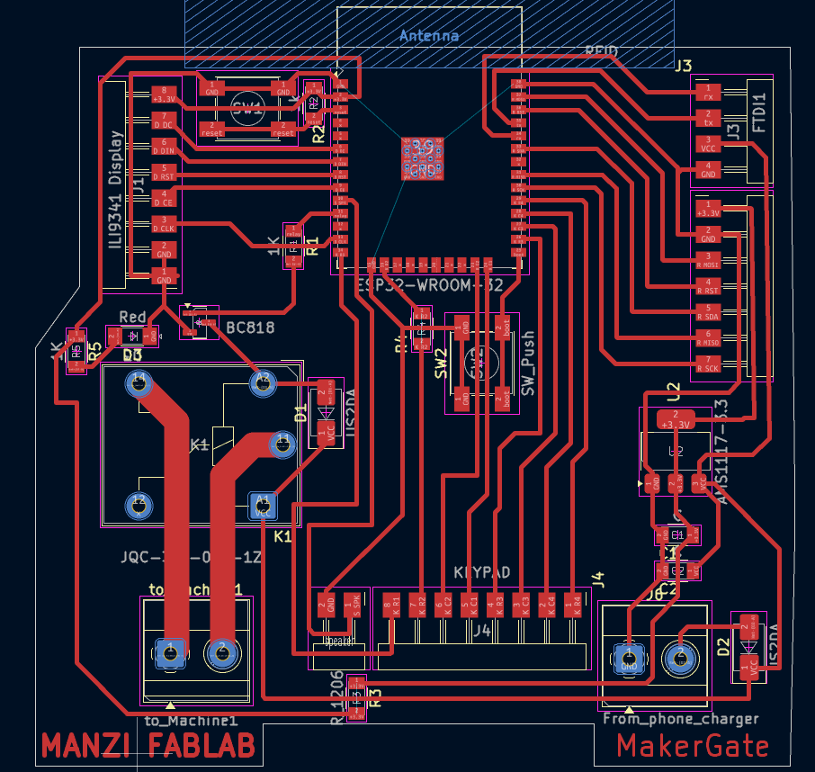
Brings everything together on one board I designed myself
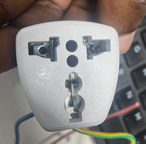
For My device to have power
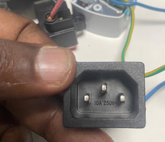
For The Machine to receive power from my device
Here's everything I had to wrangle into working together for this project:
| Component | How Many | What It Does |
|---|---|---|
| ESP32-WROOM-32 | 1 | The main brain that controls everything and connects to WiFi |
| IL9341 Display Module | 1 | Shows users what's happening and what they need to do |
| Keypad 4x5 | 1 | For typing in PIN codes and navigating menus |
| RFID Reader Module (RC522-SR04-06) | 1 | Reads the cards to identify users |
| Relay Module | 1 | Actually controls the power to the equipment |
| Transistor Q1 (NPN) | 1 | Switches the relay on and off |
| USB-A Connector | 1 | For power and programming (much easier than wire connections) |
| Voltage Regulator (AMS1117-3.3V) | 1 | Steps down 5V to 3.3V for components that need it |
| Capacitor C1 (100µF) | 1 | Smooths out power supply noise |
| Capacitor C2 (10µF) | 1 | More power filtering for the voltage regulator |
| Resistor R1 (1kΩ) | 1 | Limits current to the transistor base |
| Resistor R2 (1.2kΩ) | 1 | Pull-up resistor for reliable relay control |
| LED (Status Indicator) | 1 | Quick visual indicator that the system is running |
| Push Button (Reset and boot) | 2 | Reset button and boot mode selection |
| Diode D1 (Protection) | 2 | Protects against voltage spikes from the relay |
| Terminal Blocks | 2 | Easy connections for external equipment power |
Okay, so here's how my MAKERGATE system actually secures expensive tools. It's pretty straightforward but effective!
Starting UpWhen I power everything up, the ESP32 boots up and initializes all the components. The display shows "Ready" and the RFID reader starts listening for cards. Most importantly, the relay starts in the OFF position, so no equipment gets power until someone proves they're authorized.
Someone Wants to Use EquipmentHere's the typical flow: Someone walks up with their RFID card and holds it near my reader. The RC522 picks up the card's unique ID and sends it to my ESP32. I check this ID against my list of authorized users stored in the code. For really expensive stuff, I also make them enter a PIN on the keypad for extra security.
Granting (or Denying) AccessIf everything checks out, the display shows "Access Granted" with their name, and my ESP32 sends a signal to turn on the transistor. This energizes the relay, which closes the contacts and lets mains power flow to the equipment. If something's wrong (bad card, wrong PIN), they get "Access Denied" and the equipment stays off.
While Equipment is RunningWhile someone's using the equipment, I keep track of who it is, how long they've been using it, and display their info on the screen. Everything gets logged so we can see usage patterns and track down problems if equipment gets damaged.
Finishing UpWhen they're done, they either scan their card again or enter a code to log out. I immediately cut power to the equipment and save the session data. Simple and secure!
Safety Stuff I Built InThe beauty of my system is that it turns any dumb tool into a smart, trackable piece of equipment. No more mystery about who used what when, and expensive equipment can't "walk away" or get damaged by unauthorized users.
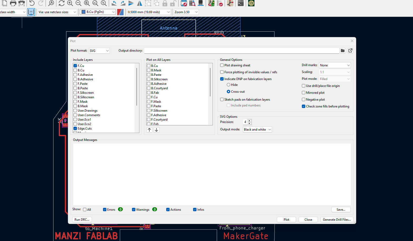
Time to turn my digital design into an actual circuit board! Here's how I did it with our SRM 20:
First, I Uploadedthe svg into Mods CE to create the actual toolpath. This step is crucial - the milling machine needs precise instructions on where to cut.
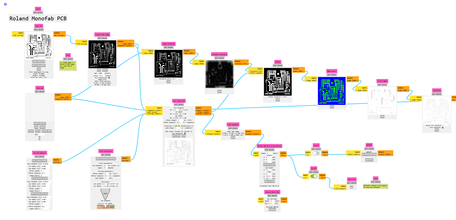
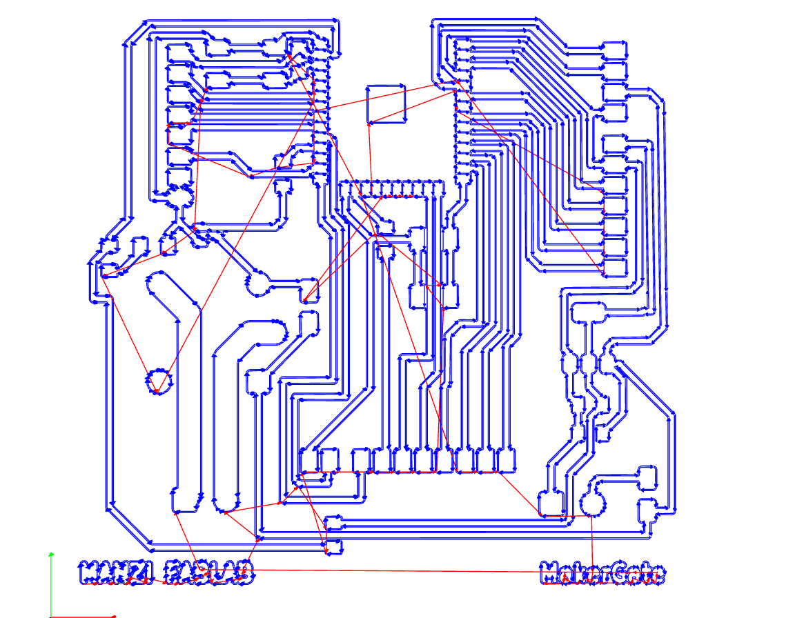
After generating the G-code, I set up the copper board in the SRM20 and started the milling process. Here's the machine doing its thing:
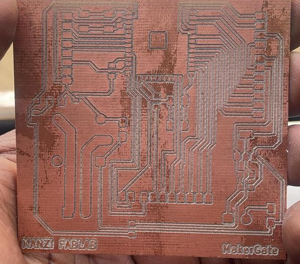
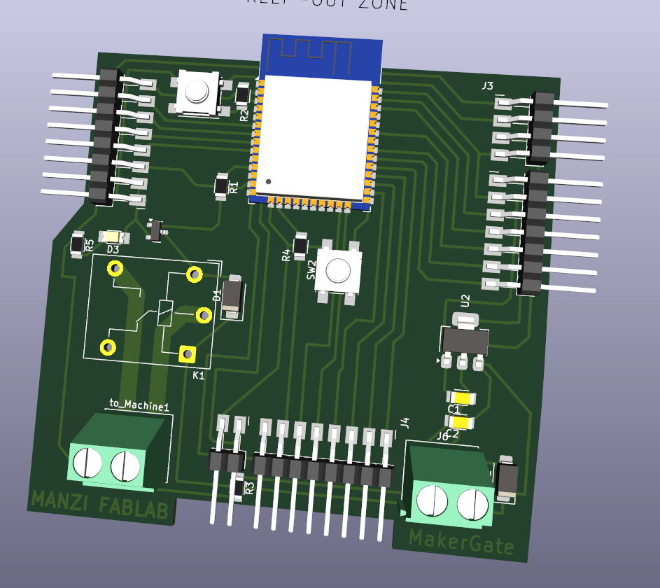
The milled PCB turned out pretty clean! No broken traces or missing pads.
Then came the tedious part - soldering all the components one by one. Started with the smallest components and worked my way up to the bigger ones.
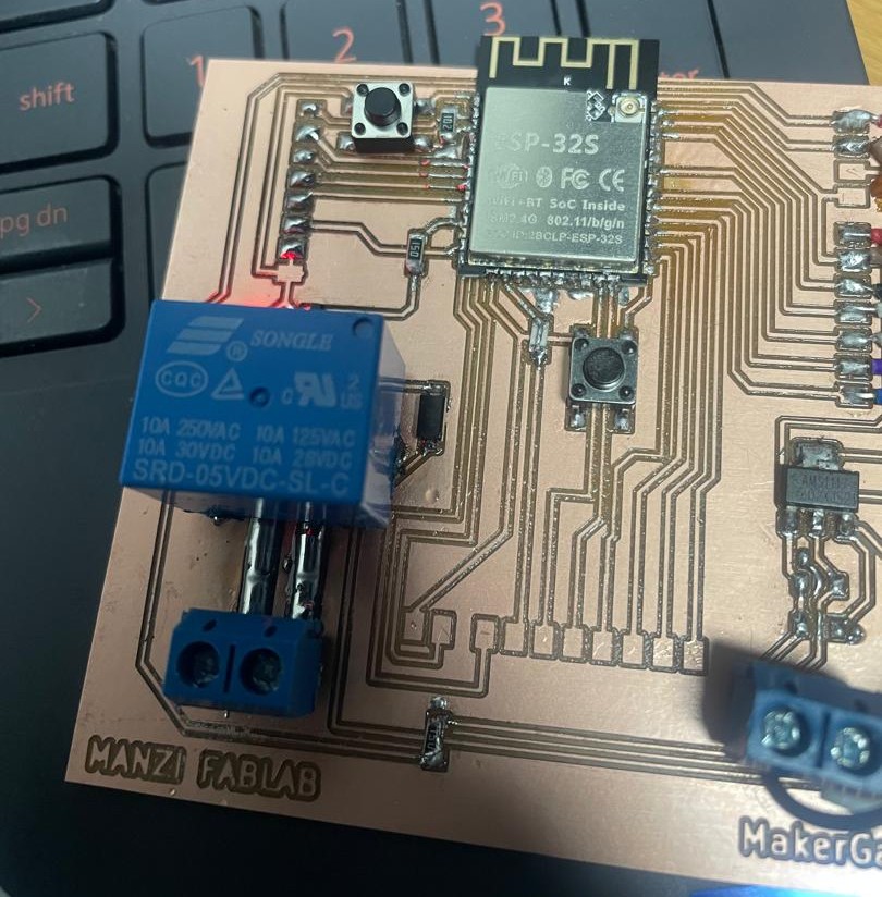
Finally got everything soldered on and connected. It actually looks like a real product!
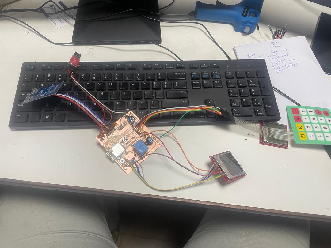
Time for the moment of truth - does everything actually work together? I started with some basic code to test the core functionality.
Here's the test code I wrote to see if the relay would respond to authentication:
Writing the code for this was actually pretty fun once I figured out how to get all the components talking to each other. Here's how I built the security logic:
#include <SPI.h>
#include <MFRC522.h>
#include <Keypad.h>
#include <Adafruit_GFX.h>
#include <Adafruit_PCD8544.h>
These are basically the instruction manuals that tell my ESP32 how to talk to each component. Without these, nothing would work!
// ESP32 pin connections
#define SS_PIN    21   // RFID reader
#define RST_PIN   22   // RFID reset
#define SCK_PIN   18   // SPI clock
#define MOSI_PIN  23   // SPI data out
#define MISO_PIN  19   // SPI data in
#define OUTPUT_PIN 26  // The important one - controls equipment power!

// Nokia display connections
#define LCD_CLK    14
#define LCD_DIN   25
#define LCD_DC    12
#define LCD_CE    33
#define LCD_RST   32
Pin 26 is the star of the show - that's what actually turns equipment on and off. Everything else is just input and feedback.
char keys[ROWS][COLS] = {
  {'1', '2', '3'},
  {'4', '5', '6'},
  {'7', '8', '9'},
  {'*', '0', '#'}
};
I mapped out the keypad so users can press '#' to submit their password and '*' to clear what they've typed. Pretty standard stuff.
void setup() {
  Serial.begin(115200);
  pinMode(OUTPUT_PIN, OUTPUT);
  digitalWrite(OUTPUT_PIN, LOW); // Start with equipment OFF

  // Get all components talking
  SPI.begin(SCK_PIN, MISO_PIN, MOSI_PIN, SS_PIN);
  mfrc522.PCD_Init();
  display.begin();

  // Welcome screen
  display.println("RFID Security");
  display.println("System Ready");
  display.println("Place card");
  display.println("near reader");
}
The most important line here is setting OUTPUT_PIN to LOW - this ensures equipment starts OFF and stays that way until someone proves they belong!
void loop() {
  // Looking for RFID cards
  if (mfrc522.PICC_IsNewCardPresent() && mfrc522.PICC_ReadCardSerial()) {
    cardDetected = true;
    waitingForPassword = true;
    Serial.println("Card detected! Please enter password:");
  }
}
This constantly checks for cards. When it finds one, it reads the unique ID and asks for a password. Two-factor security!
if (key == '#') {
  // Check if password is correct
  if (enteredPassword == correctPassword) {
    Serial.println("Password CORRECT! GPIO 26 ON");
    passwordEntered = true;
  } else {
    Serial.println("Password INCORRECT! Try again:");
    enteredPassword = "";
  }
}
When someone hits '#', I check if they entered "1234" (my default password). Right password = access granted. Wrong password = try again!
// Only turn on equipment if BOTH conditions are met
bool shouldActivate = cardPresent && passwordEntered;
digitalWrite(OUTPUT_PIN, shouldActivate ? HIGH : LOW);
This is the heart of my security system. Equipment only gets power when someone has both a valid card AND entered the correct password. Remove either one and it shuts off immediately.
void updateDisplay() {
  if (!cardPresent) {
    display.println("Place card near reader");
  } else if (waitingForPassword) {
    display.println("Enter Password:");
    display.print("Pass: ");
    for (int i = 0; i < enteredPassword.length(); i++) {
      display.print("*");  // Security - show asterisks
    }
  } else if (passwordEntered) {
    display.println("ACCESS GRANTED");
    display.println("Machine: Running");
  }
}
The display always tells users what's happening and what they need to do next. And yes, passwords show up as asterisks for security!
Getting all these components to work together is one thing, but packaging them into a usable, professional-looking system is another challenge entirely. Here's how I approached the packaging and integration of my MAKERGATE system:
I designed the system with specific packaging requirements in mind:
• Inside power access case to prevent bypassing
• Locked access to main control board
• RFID reader and keypad accessible for user interaction
• Front-facing keypad
• Clear view of LCD display
• Back-mounted power connections
• Left-mounted for rfid
• Programming port access for updates
• Dust protection for electronics
• Ventilation for heat dissipation
• Moisture resistance for workshop environment
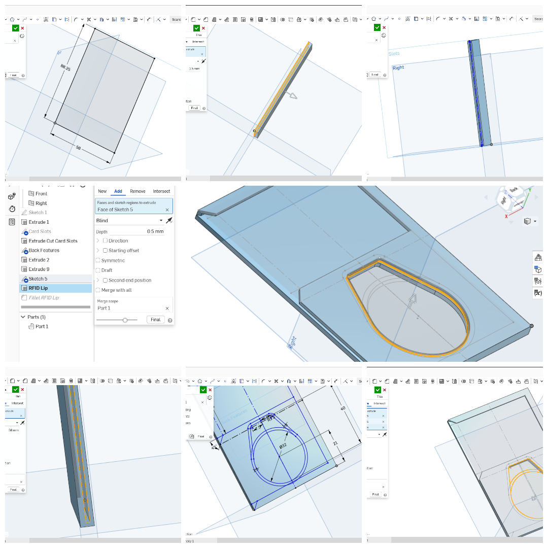
I used Onshape to design the enclosure, focusing on:
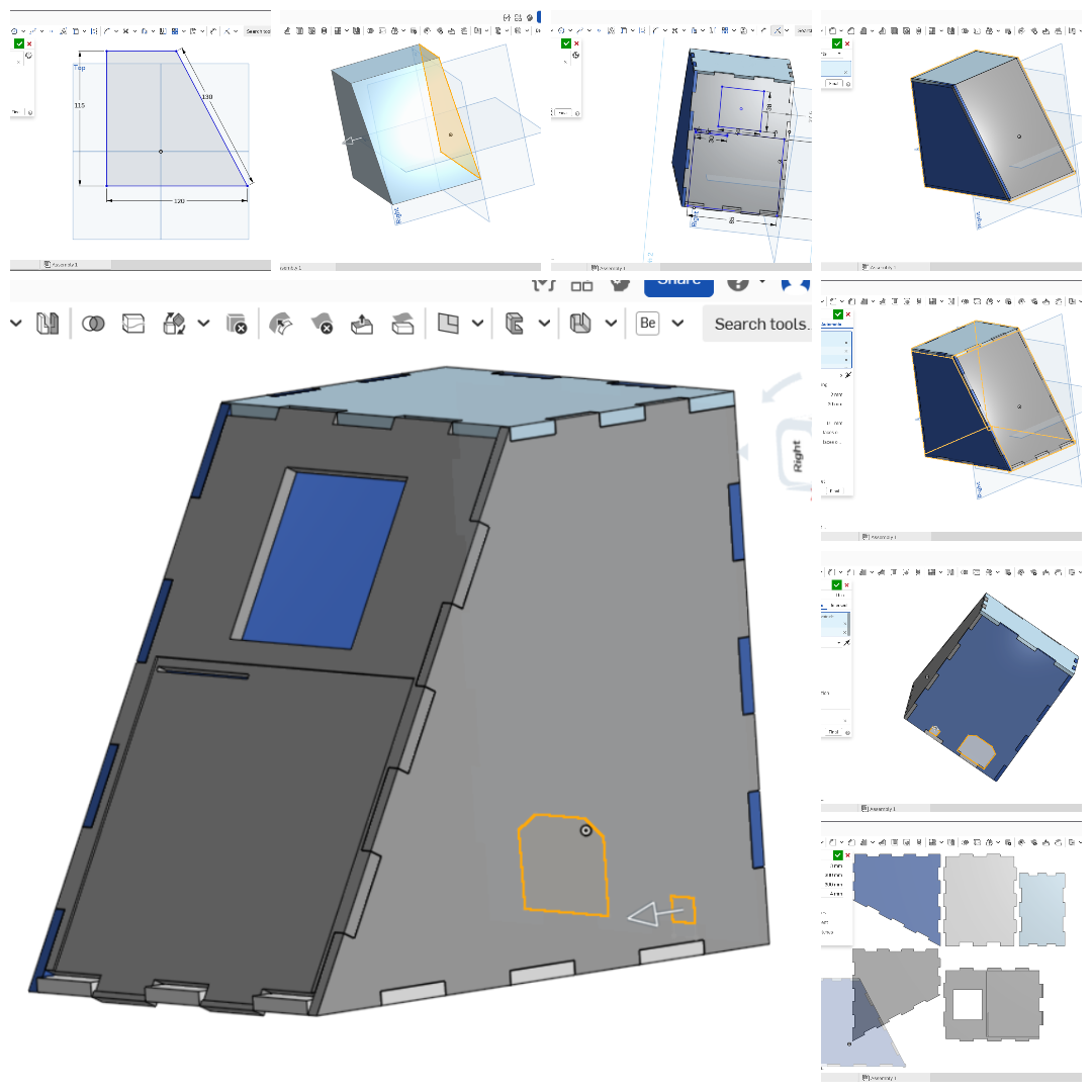
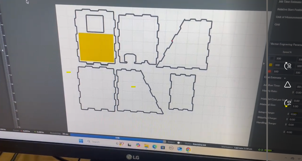
I also used Onshape to design IT
.png)
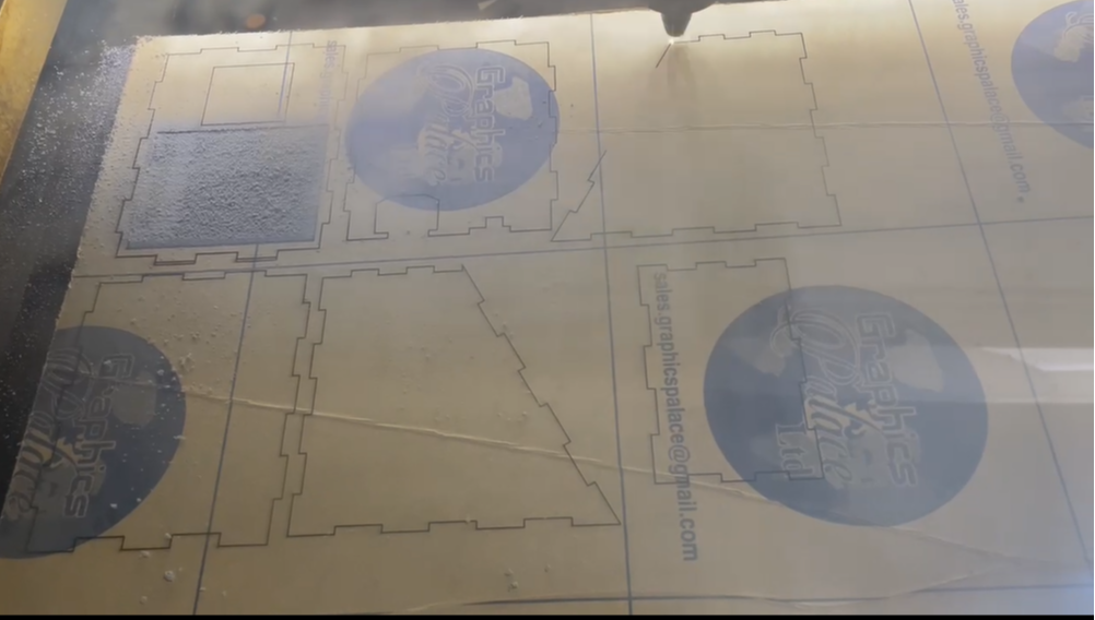
After laser cutting i started the assembly, Finally all was attached together expect the backcover for installation
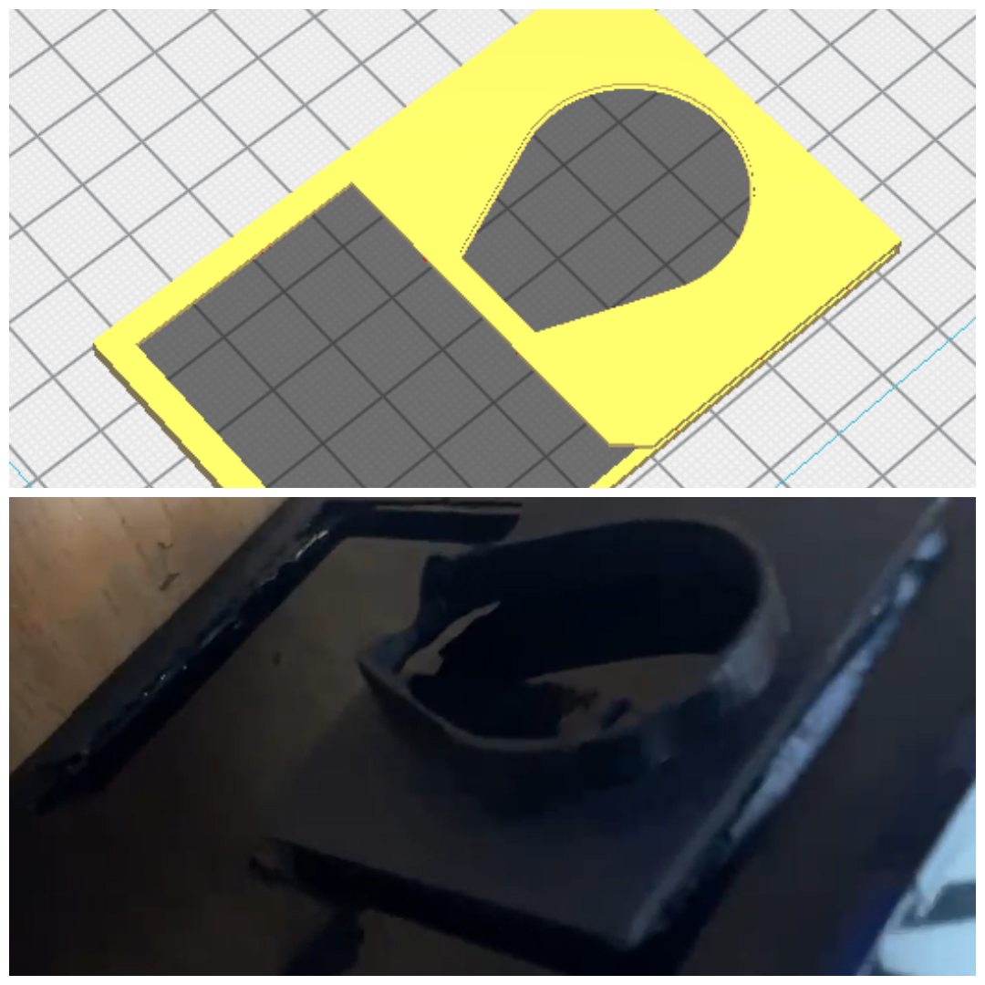
.png)
After i carefull fit everything together make sure to sparate the board and the powersupply, display, keypad and rfid also attached
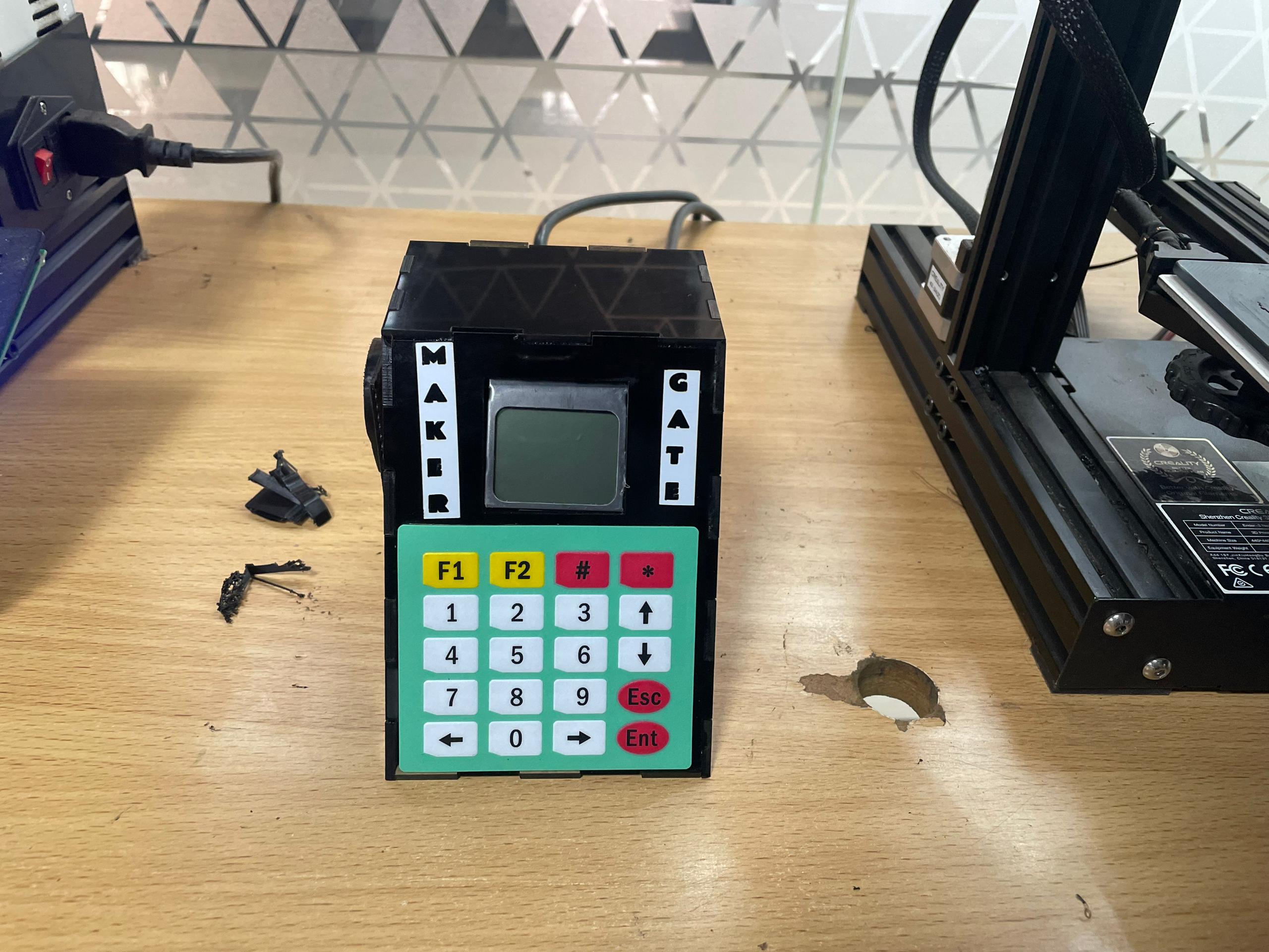
My Final Product, i just add the sticker
My packaging approach successfully achieved:
No loose connections or intermittent failures
Easy to troubleshoot and repair individual components
Design can be replicated for multiple tool stations
Clean, easy appearance that users trust