What I Actually Learned
This week I got to try plasma cutting for the first time. Honestly, it was pretty intimidating at first - you're basically using electricity to create super hot plasma that melts through metal. But once I got the hang of it, it was really satisfying to see clean cuts happening automatically from my design file.
The biggest thing I learned is that you can't just jump in and start cutting. There's a lot of setup involved, and getting the G-code right is crucial. I also realized how important it is to do test cuts first - I probably would have messed up my piece if I hadn't practiced on some scrap metal first.
Making the Fishbone Wrench with Plasma
So for this assignment, I decided to cut out the Fishbone Wrench from a vector that i find in on this website vectorsfile.com/download on a piece of iron sheet. I figured it would be something useful for the lab and let me try out this plasma cutting process that we haven't used in class yet.
What I Did
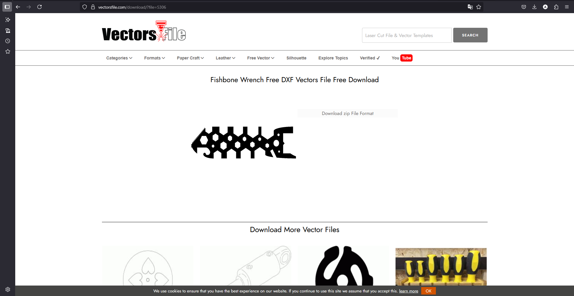
I download the Fishbone Wrench from the site as a DXF file since that's what the CAM software wanted.
Making the G-code
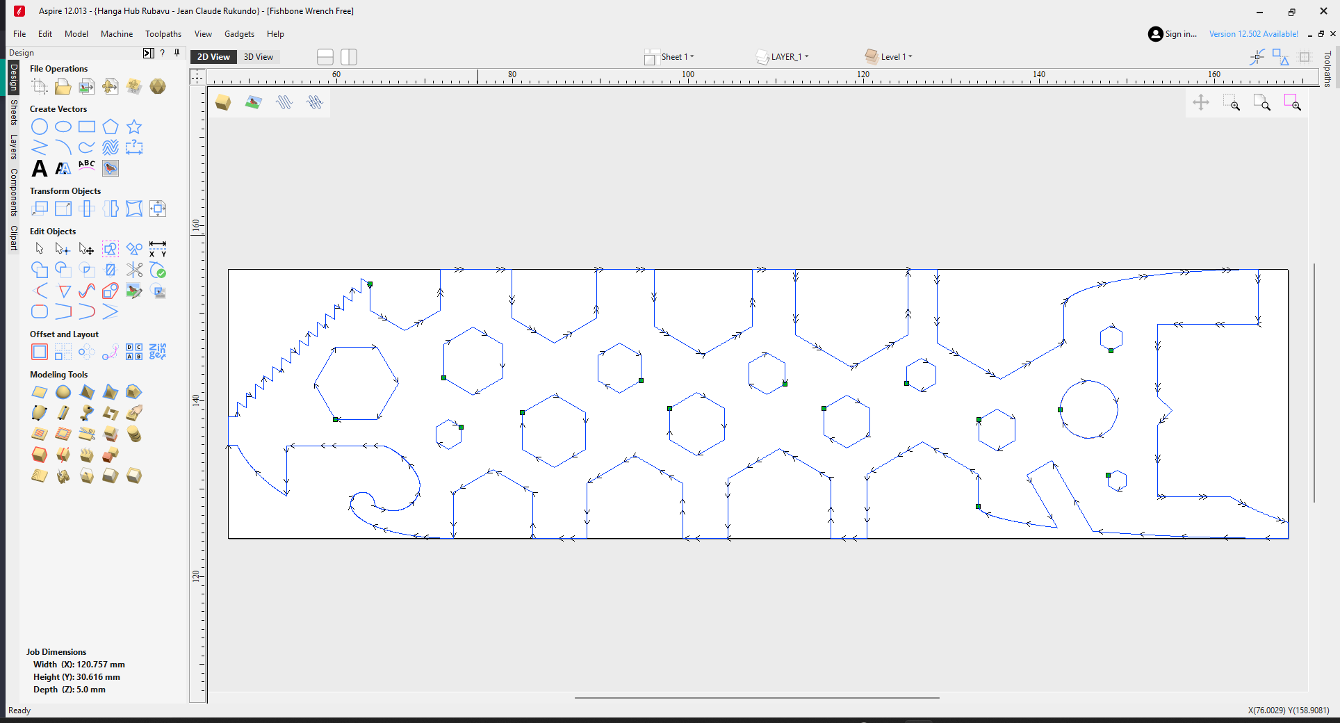
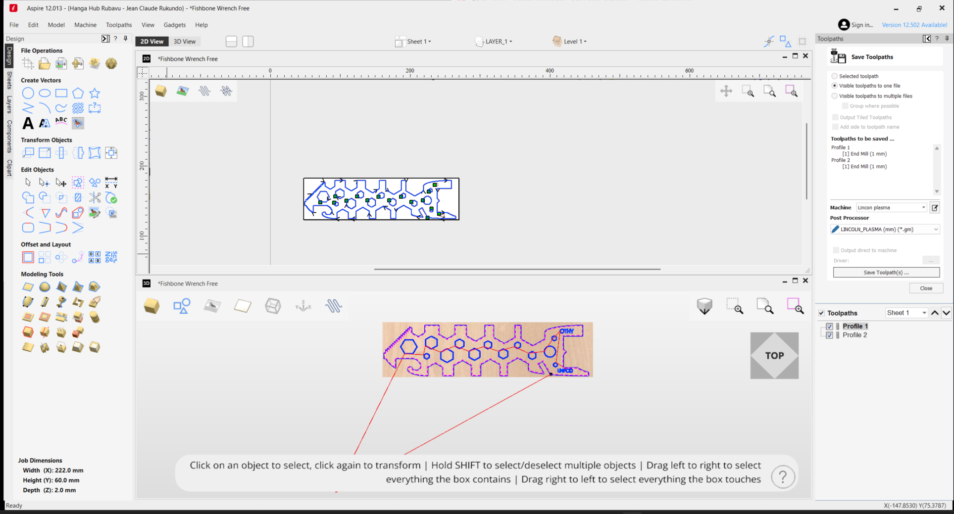
Used Aspire to create the cutting paths and generate G-code with the Lincoln plasma post-processor.
This part was new to me. I used Aspire and had to pick the right post-processor for the Lincoln plasma cutter. Mr, Josue helped me with this part since I had no idea what I was doing. The Profile Toolpath function basically tells the machine where to cut, and the post-processor makes sure the G-code format works with our specific plasma cutter.
Setting Up the Machine

Had to check all the connections - air compressor, cutting head, and power. Added water to the table for cooling.
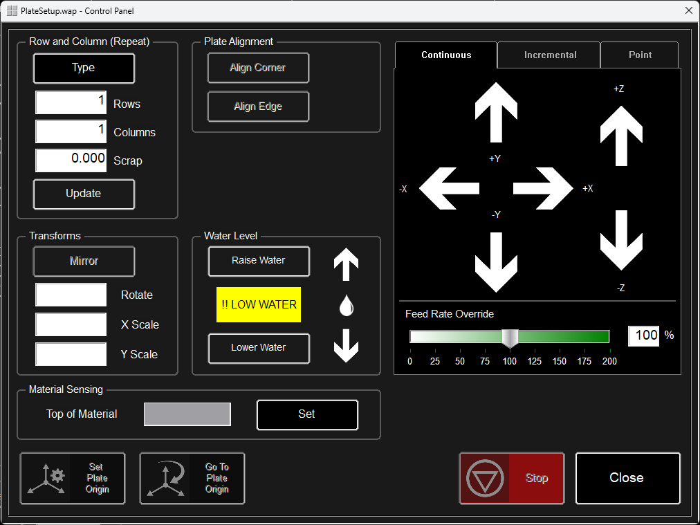
Put the iron sheet on the bed and set the origin point so the machine knew where to start cutting.
This was the nerve-wracking part. Had to make sure the air compressor was connected, the cutting head was properly attached, and there was water in the table (apparently this helps with fumes and cooling). Setting the origin was important - if you get this wrong, your cut ends up in the wrong place on your material.
Test Cuts First
Did some practice cuts using built-in shapes before risking my actual design.
Simple shapes to test if everything was working right.
The test cuts looked good, so I knew I was ready for the real thing.
I'm glad I did test cuts first. The machine has a "dry run" mode where it moves around without actually cutting - that's useful for checking that your toolpath looks right. Then I did some actual cuts on scrap metal to make sure the settings were good.
The Actual Cutting
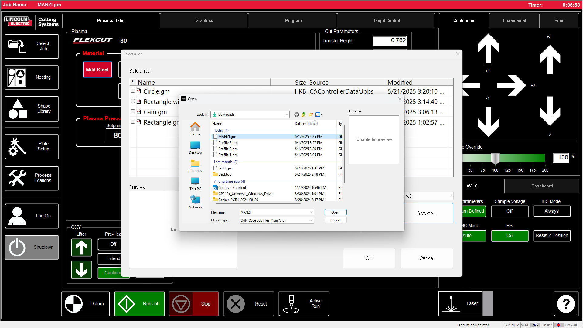
Finally cutting my design - selecting the my gcode from Aspire.
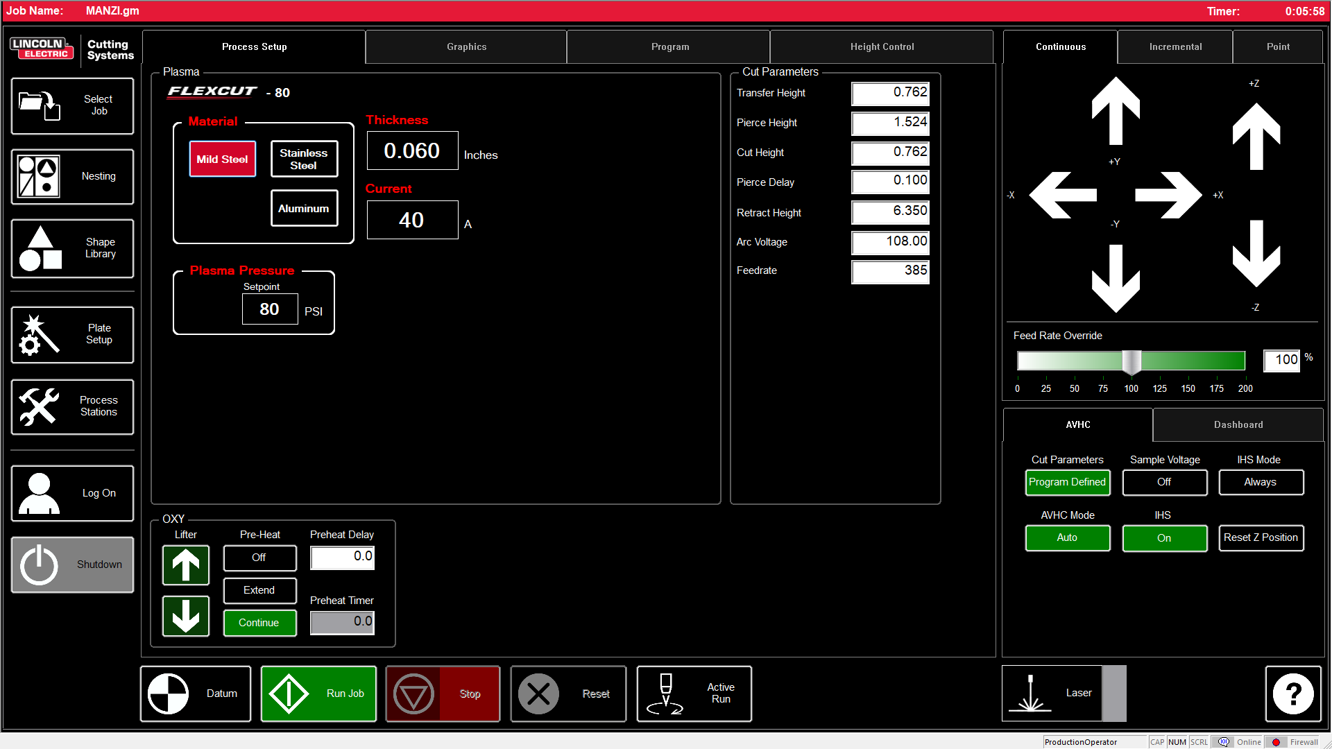
After i checked the settings of the cutter
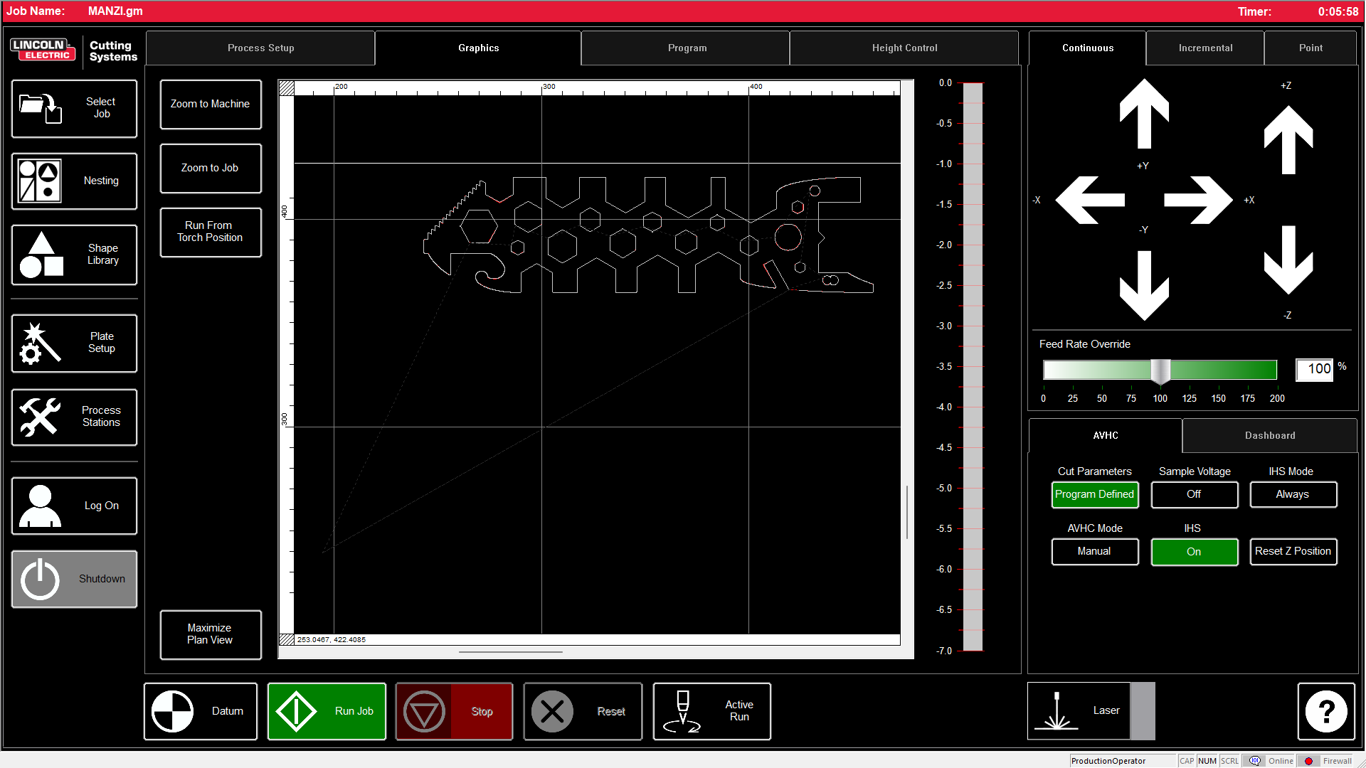
view the job in the Lincoln software
view the job in the process
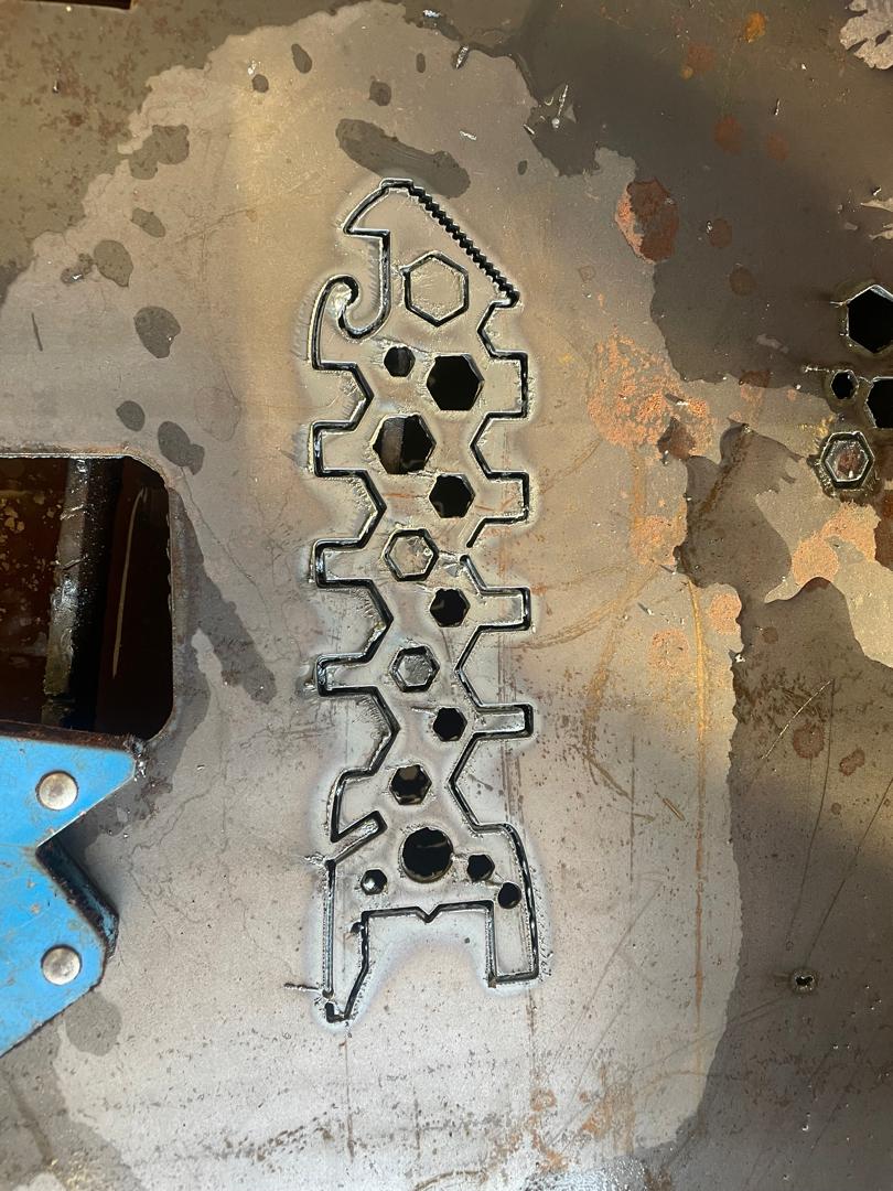
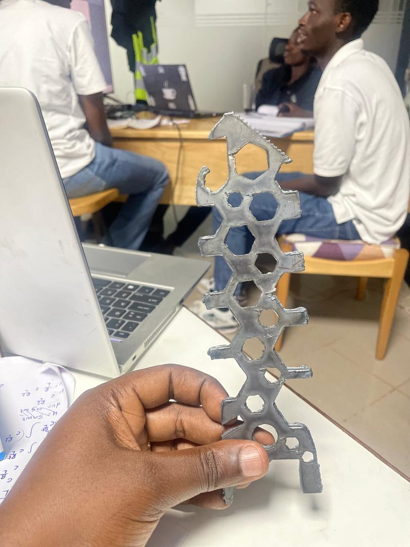
Final piece cut from 1.5mm iron -
Final piece cut from 1.5mm iron -
The actual cutting was pretty straightforward once everything was set up. The plasma follows toolpath exactly, and you can see the molten metal getting blown away. It's loud and there are sparks.
What I Figured Out
A few things I learned from this project:
- The post-processor really matters - wrong one and your G-code won't work
- Test cuts save you from wasting good material on mistakes
- Safety gear isn't optional - this stuff gets really hot
- Your design has to work with what the process can actually do
- Setup time is way longer than actual cutting time
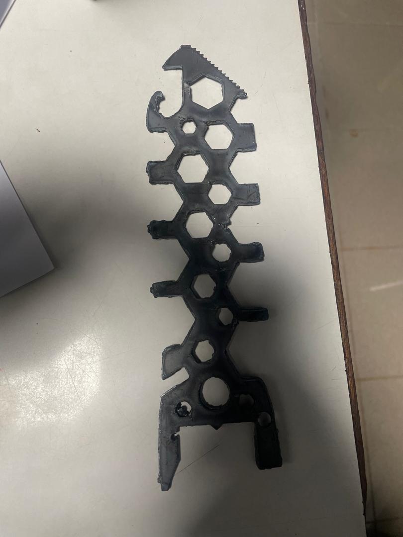
Next step is to grind off the rough edges and maybe paint it so it looks more professional.
Files
- Design File:
- G-code File: