Personal Reflection: What I Learned
The Computer-Controlled Machining week gave me practical skills I couldn't get from textbooks alone. I now understand how digital designs translate to physical objects through toolpaths, and how critical proper setup is for quality results. The hands-on experience with the ShopBot taught me that safety isn't just about wearing goggles – it's about thorough planning and understanding your machine.

These practical lessons in tolerances and material behavior will help me with all future fabrication projects.
My UNIPOD Sawhorse Storage Project
For this week's assignment, I designed and fabricated a sawhorse storage unit using CNC machining. This project allowed me to apply parametric design principles and CNC fabrication techniques to create a functional piece of furniture. Below, I document my step-by-step journey from initial concept to final manufacturing.
Initial Design in Onshape
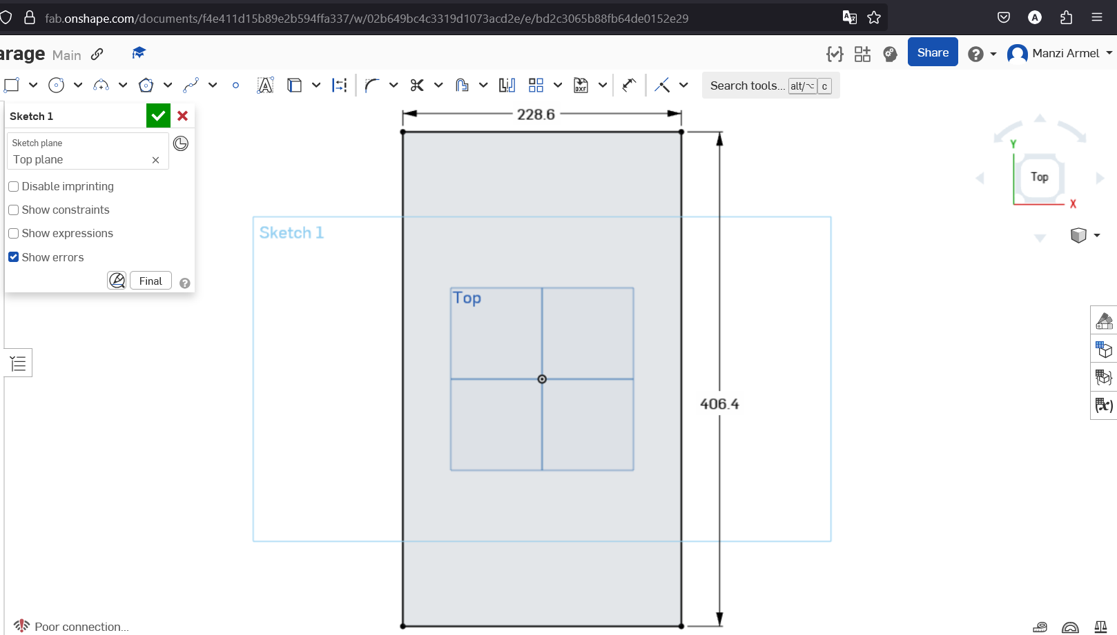
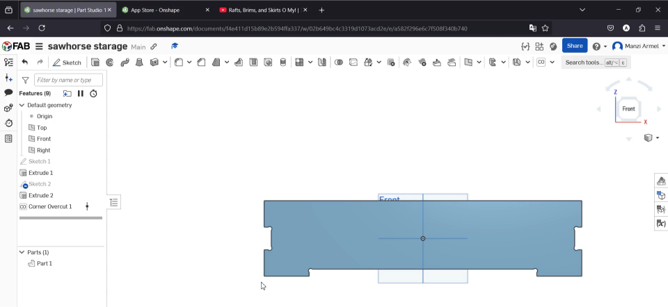
started with the side part with a rectangle
where I created a simple trapezoidal shape for the main body of the sawhorse. I started with the "Top" view to establish the basic shape. The blue coloration indicates this is still in the sketch phase.
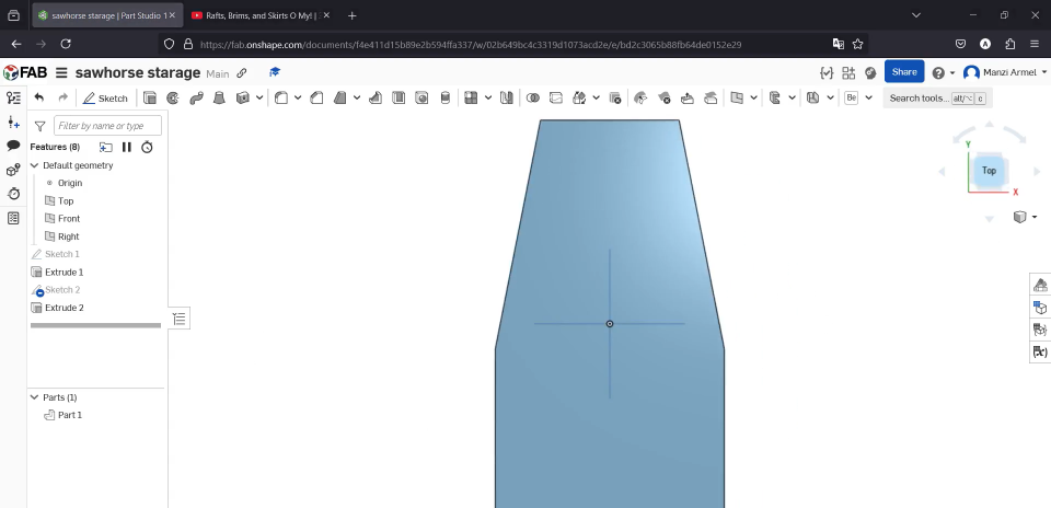
Once I was satisfied with the basic shape, I used the Extrude tool to give my 2D sketch some thickness. This step transforms the flat sketch into a 3D object with volume. I configured the extrusion to be a solid shape with a thin wall surface, which would later allow me to create the hollow structure needed for storage.
Working with Multiple Sketches:
- The trapezoid shape was carefully designed to provide both stability and storage space
- The extrusion operation was configured to create a solid body that would be modified further
- I paid special attention to the angle of the sides, which would determine the structural stability of the final sawhorse
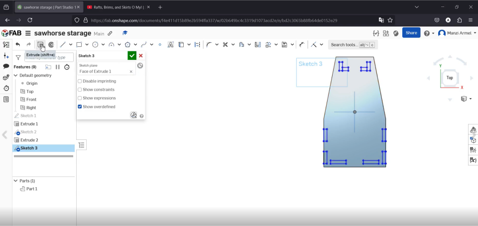
To add mounting points for connecting pieces, I created another sketch directly on the front face of the extruded trapezoid. I used the "Face of Extrude 1" as my sketch plane, which allowed me to draw directly on the 3D model. The blue lines in this screenshot show me working on adding connection features.
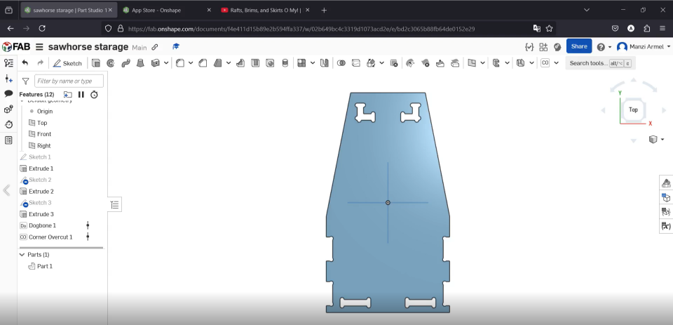
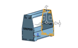
After adding several design elements, I could view the full model with all the cutouts, joinery, and features applied. The name "UNIPOD" is visible on the side, showing my design intent to make the piece both functional and aesthetically pleasing. The orange highlighted edges indicate the model's contours that would eventually be cut by the CNC machine.
Adding Design Features:
- I incorporated "dog bone" corners in interior right angles to ensure proper machining since the CNC end mill has a round profile
- The UNIPOD text was added as a cut-through feature to give the piece a unique identity
- I designed connector slots along the edges to allow for assembly without additional hardware
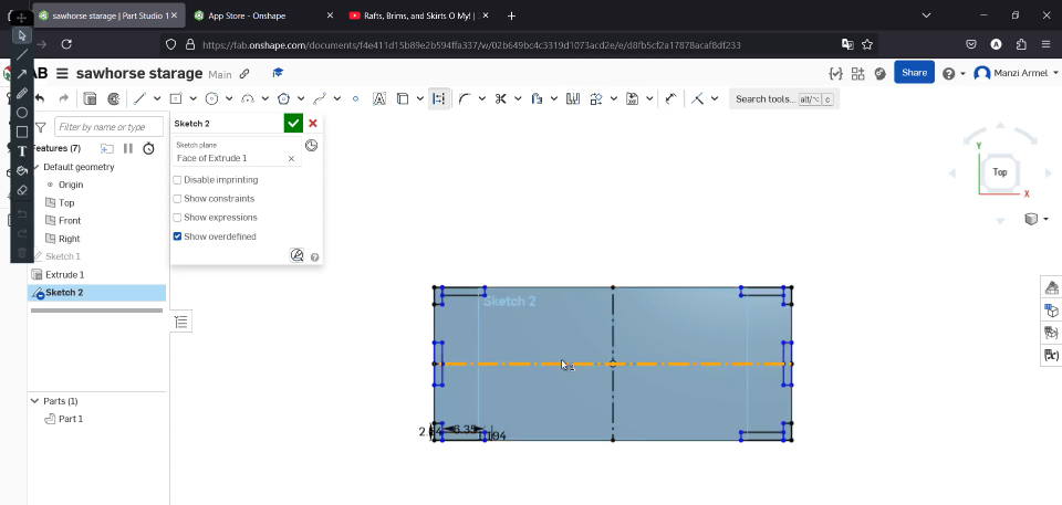
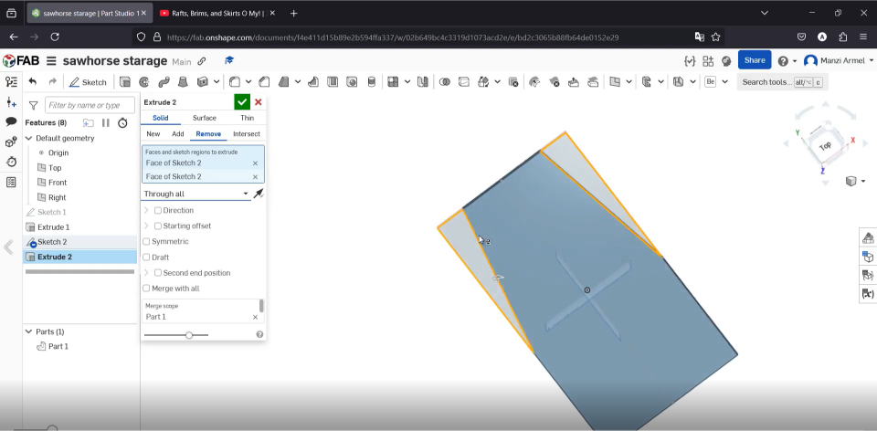
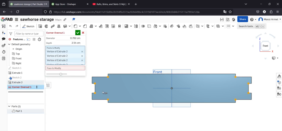
Switching to Sketch 2, I began adding more detailed features. Using the Face Selection tool, I could create new sketches on specific surfaces of my 3D model. This workflow allowed me to progressively add complexity to the design while keeping everything parametrically linked.
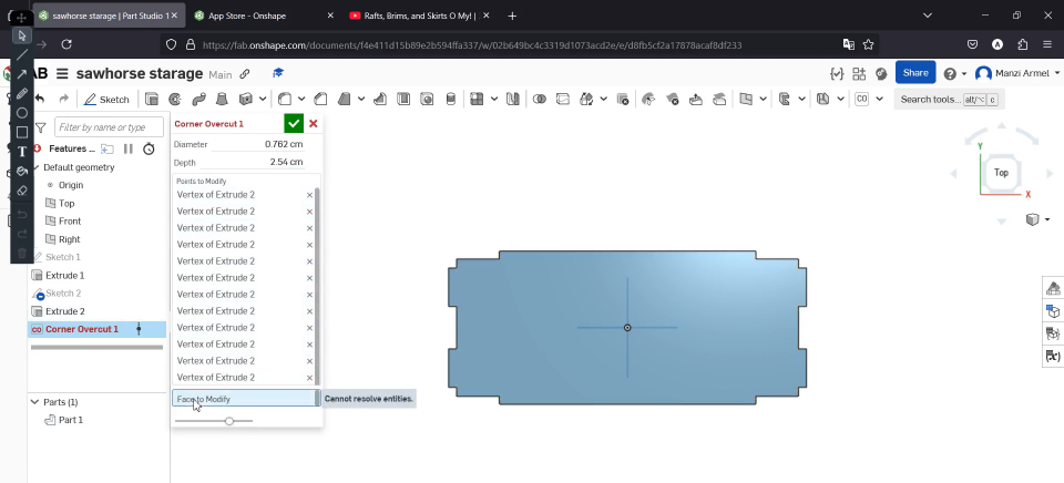
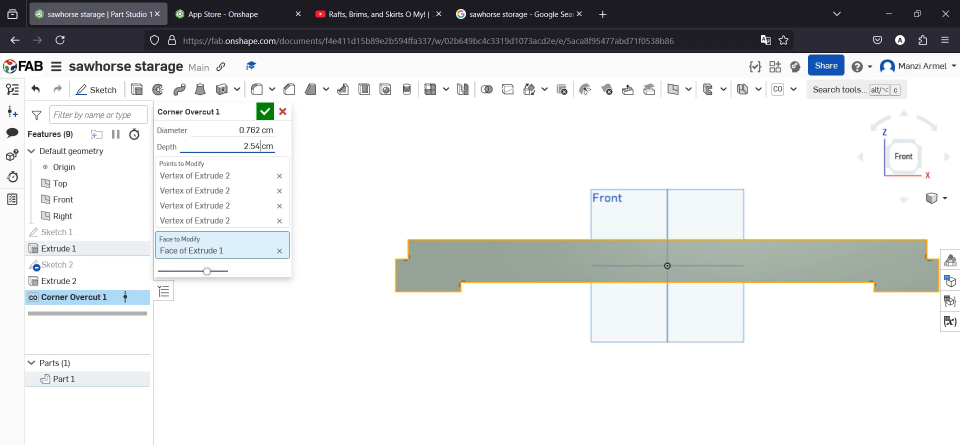
One critical feature I added was the corner overcut (visible in the parameters panel). This technique creates rounded interior corners with extensions to allow perfect fitting of parts despite the circular path of the CNC end mill.
Finalizing Design and Preparing for Manufacturing
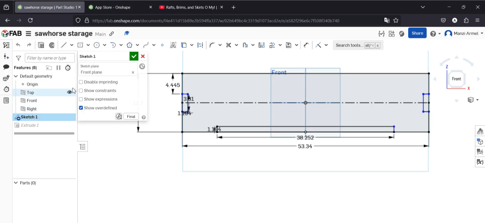
I finalized the dimensions of the main structure in the front view. The sketch shows precise measurements: 533.4 mm width and 127 mm height, with interior spacing carefully calculated. Adding dimensions at this stage ensures the design is manufacturable and meets my specifications before moving to production.
The completed 3D model shows all components of my sawhorse storage design from the front view. Note how the "Front" text indicator helps orient the piece during manufacturing. This view confirms that all cutouts and joinery features have been properly applied and are ready for CNC machining.
It followed by designing the upper base witch look like the first base but smaller
the front upper part was a bit different with the front lower part
The fully designed assembly shows all components properly positioned and ready for manufacture. After completing the 3D modeling phase, I moved to the Assembly workspace in Onshape to verify that all parts would fit together correctly. The "Front" text indicator remained visible to ensure proper orientation during machining.
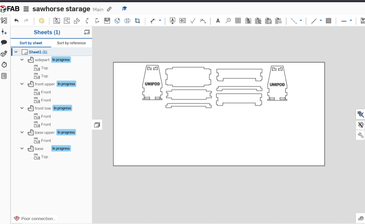
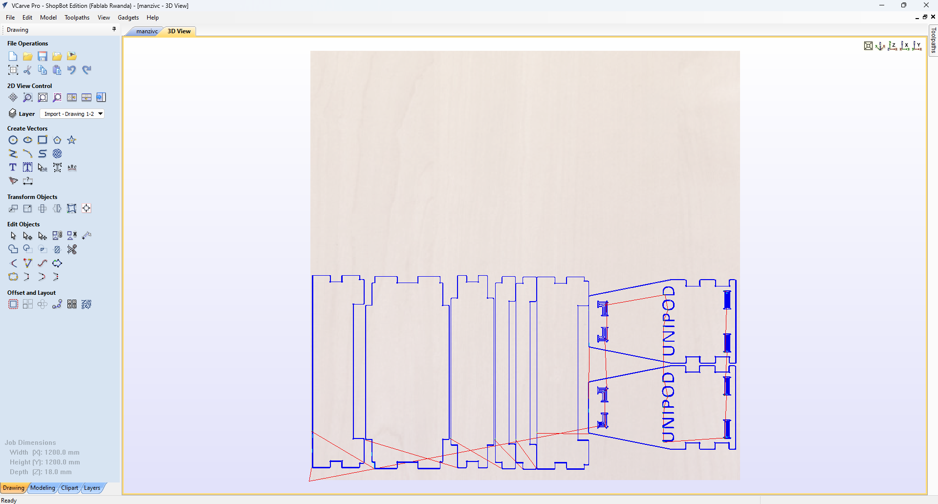
Transitioning to the 2D manufacturing view for the VCarve Pro (ShopBot Editor), I prepared my design for actual machining using drawing feature in the onshape. This converts the 3D model into a series of 2D toolpaths that the CNC machine can follow.
Generating Toolpaths for CNC Machining
VCarve Pro Toolpath Generation:
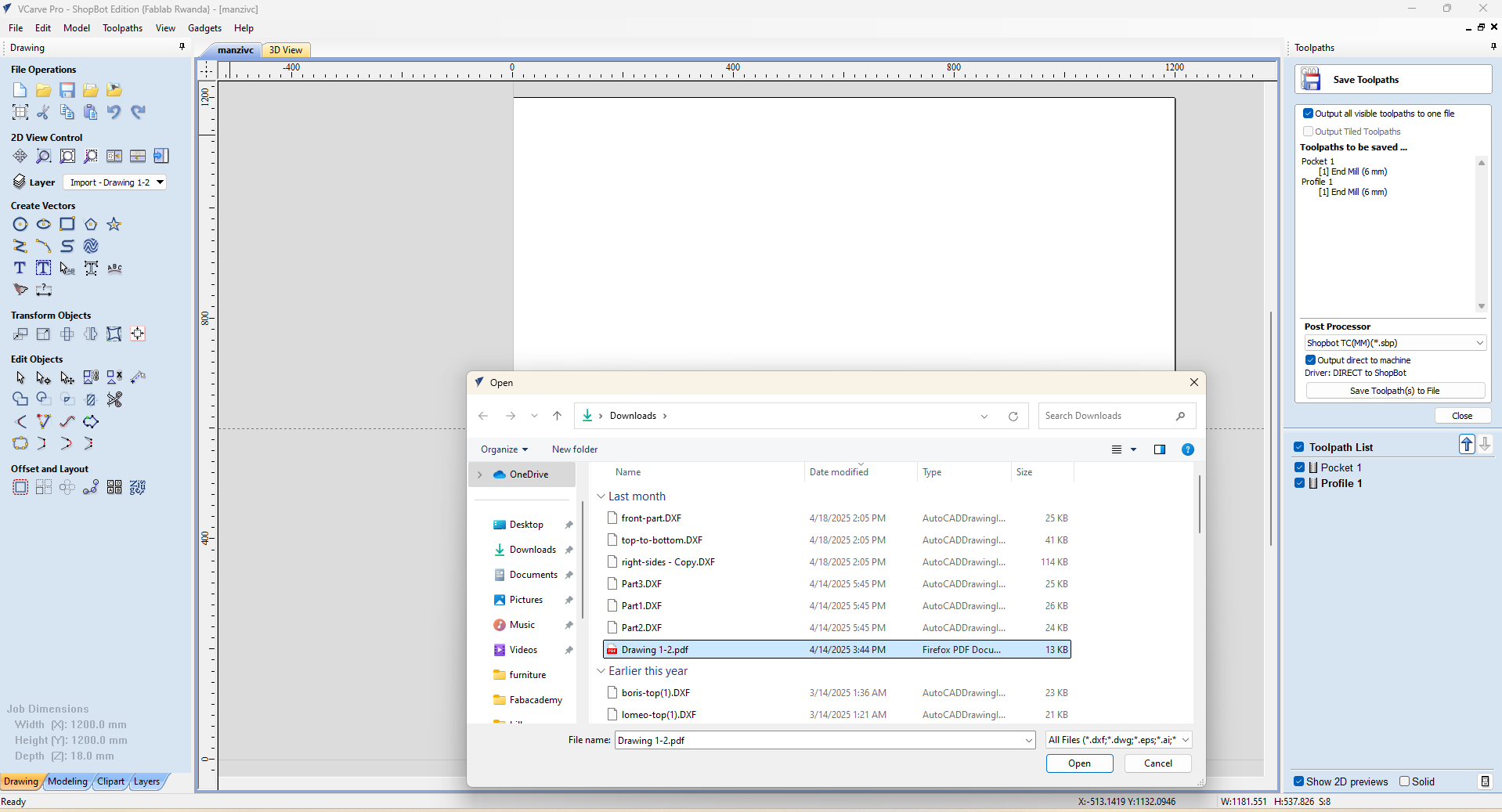
- I exported my Onshape design as DXF files for each component
- In VCarve Pro, I imported and arranged these files to optimize material usage
- The software provides specialized tools for creating efficient cutting paths for CNC machines
- Each line represents a path that the CNC tool will follow during machining
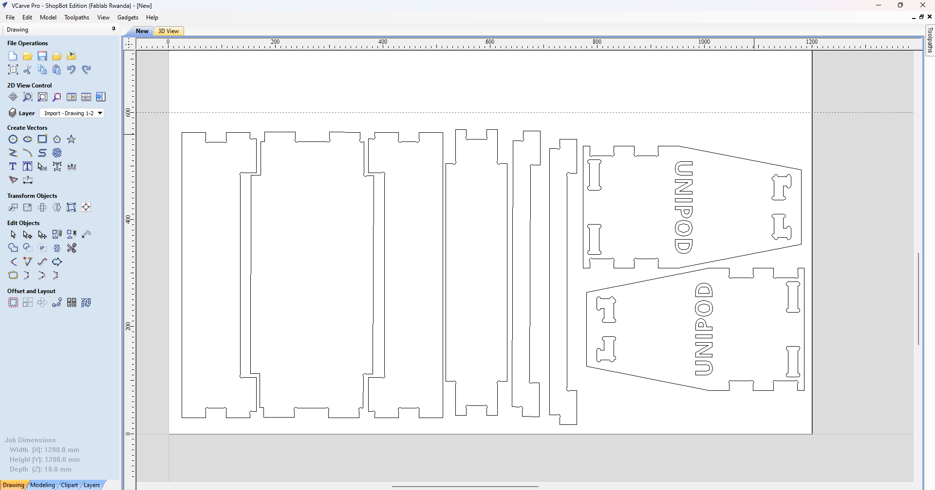
i arranged the job to fit to a minimal space
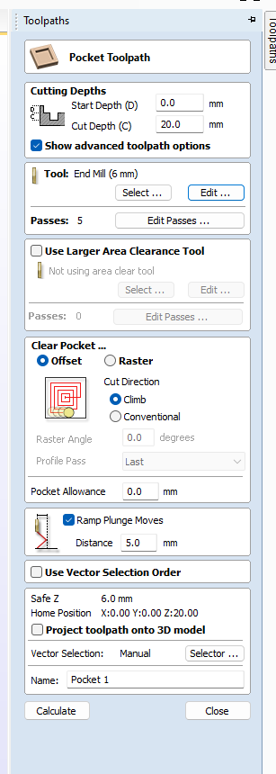
For the Pocket toolpath (interior material removal), I configured similar cutting parameters but with some key differences. I enabled "Ramp Plunge Moves" with a 5mm distance to allow the tool to enter the material gradually. This technique prevents tool breakage by avoiding straight plunges into the material. The "Climb" cut direction was maintained for optimal cutting performance.
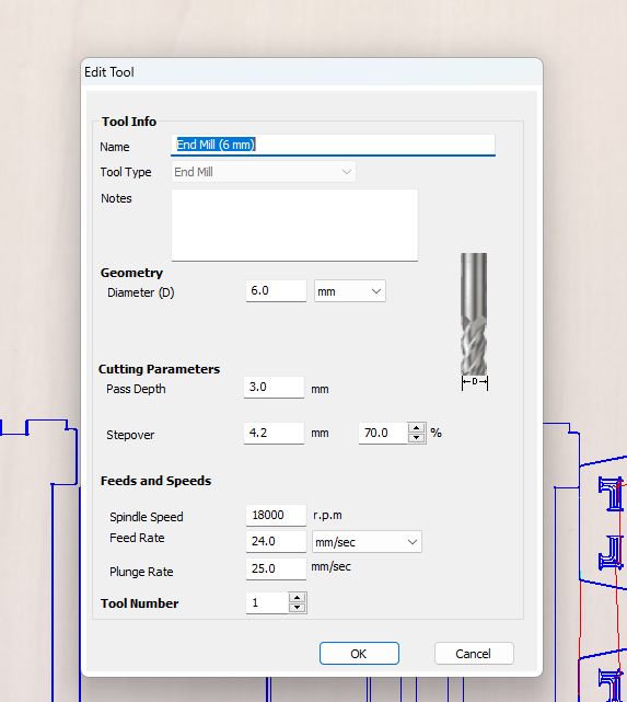
Precise tool configuration was essential for successful machining. For my 6mm end mill, I specified cutting parameters including 3mm pass depth, 4.2mm stepover (70%), 18000 RPM spindle speed, and 24mm/sec feed rate. These settings determine how quickly and aggressively the tool removes material, balancing between efficiency and quality.
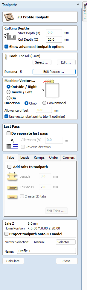
For the Profile toolpath, I configured detailed cutting parameters. I set a 20mm cut depth and selected the 6mm end mill tool. The advanced options show that I chose "Outside/Right" machining vectors and "Climb" direction for the best finish quality. These settings determine how the CNC bit will approach and cut along the design outlines.
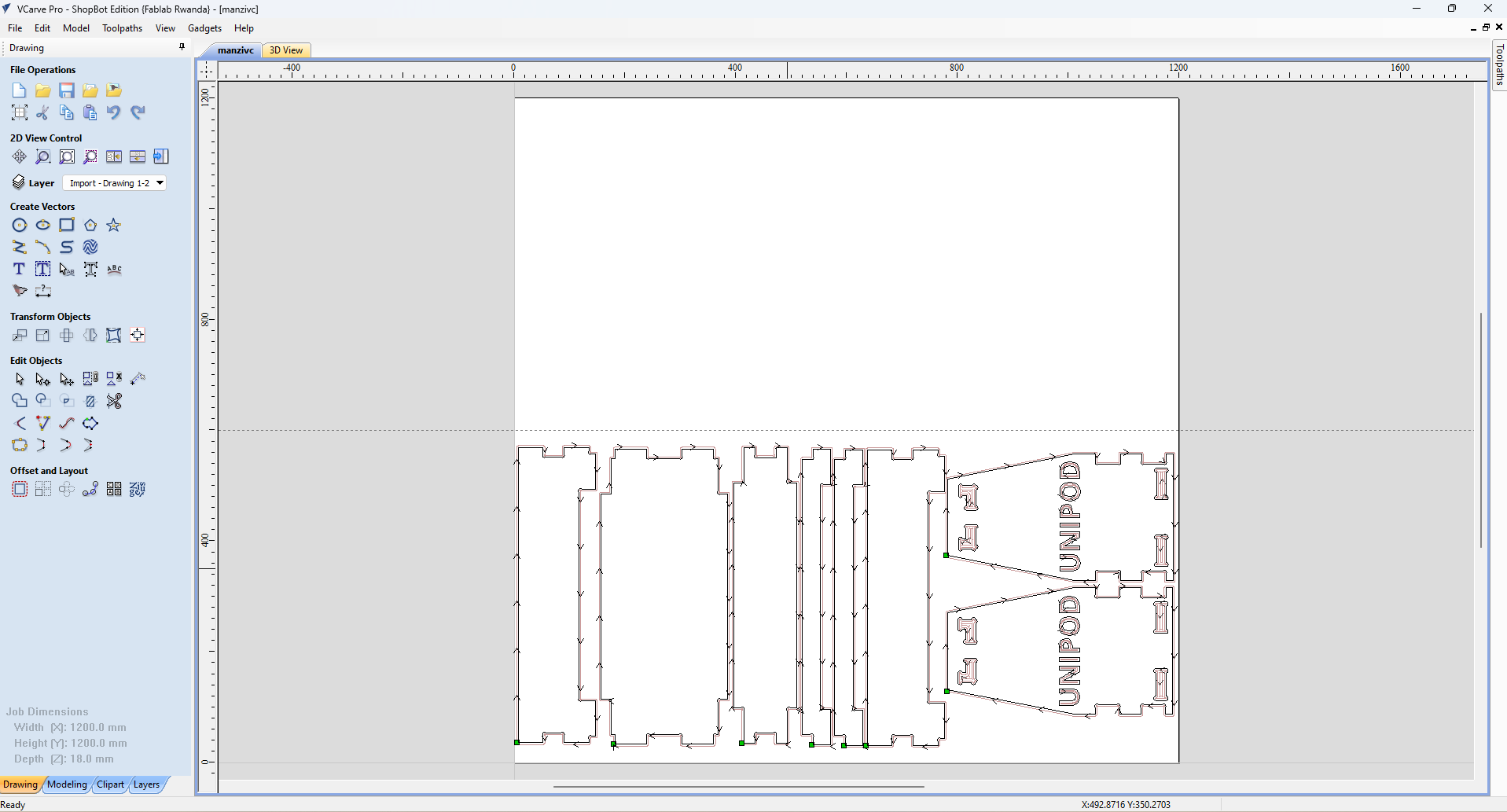
2d view of the toolpath created
3d view of the toolpath created
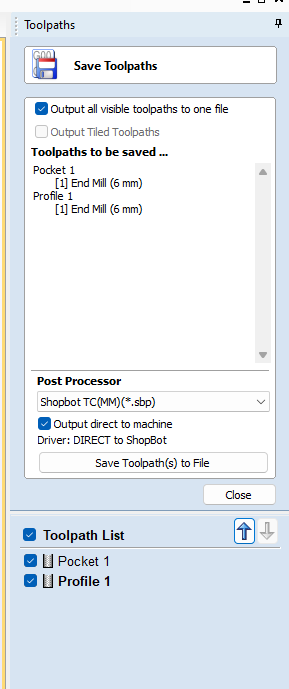
In the final step before machining, I saved my toolpath file and prepared to load it into the ShopBot CNC machine.
Running the job in the shopbot machine
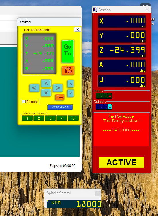
I started the CNC shopbot as showned in the group assignment fixed the tool bit as well, then zeroed the cnc by pressing c3
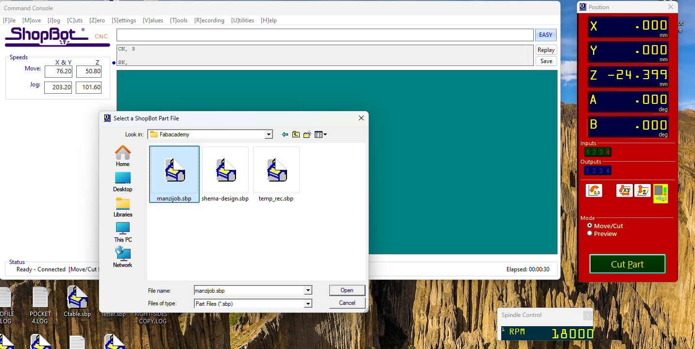
Then i loaded the gcode created by the vcarve software
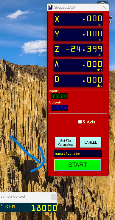
file set and clicked start
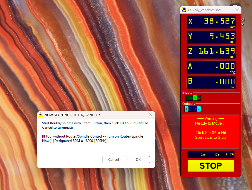
this is a warning to prevent you starting the job without turn on the spindle, witch i did
Machine running and final product
Manufacturing Reflections
Throughout this CNC machining project, I learned several valuable lessons:
Key Takeaways:
- Parametric design in Onshape allowed me to easily adjust dimensions and features as needed
- Interior corner treatments (dog bones and overcuts) are essential when designing for CNC machining
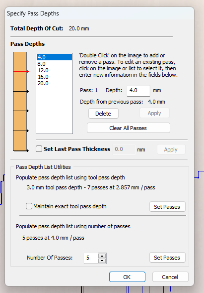
- Proper toolpath configuration, including multiple shallow passes, is crucial for clean cuts
- Optimizing material layout in VCarve Pro minimized waste and machining time
- Text and decorative elements can be integrated directly into functional parts
- ORGINAL File for 3d design with onshape 3d design
- ORGINAL File for shopbot gcode and vcarve.zip shopbot gcode and vcarve zip