Personal Reflection: What I Learned from 3D Printing
During our group assignment, I gained crucial hands-on experience with 3D printing technology. Bed leveling taught me the importance of precise calibration—adjusting the Z-offset to just 0.1mm using the paper method was a revelation. Setting up Ultimaker Cura showed me how digital models transform into printable objects through slicing software.
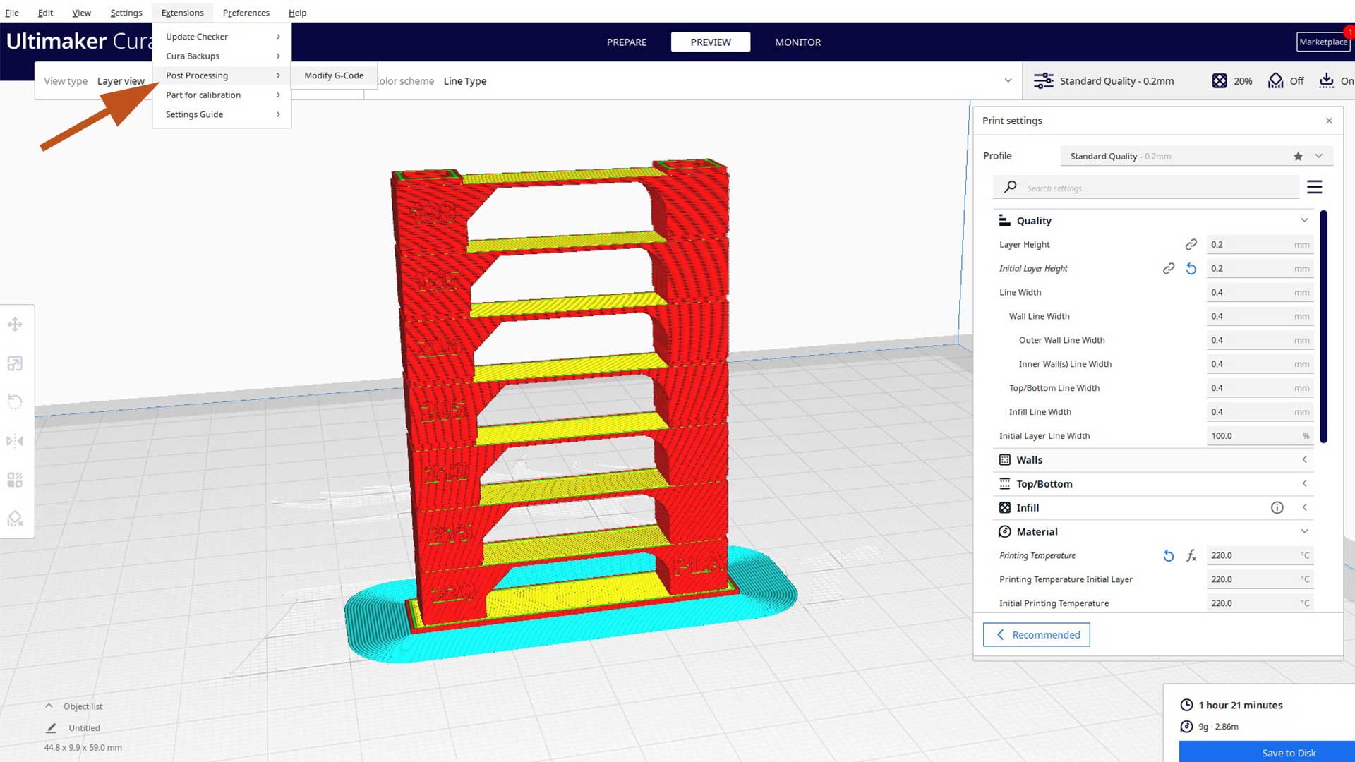
Temperature testing with the tower print revealed how critical finding the optimal temperature is for print quality. The overhang test demonstrated that 55 degrees is our printer's maximum angle without supports, knowledge that will directly influence my future designs.
For my 3d printing I Created a Ball Bearing using OnShape
my approach to modeling a ball bearing in OnShape. This document outlines the step-by-step process I used to create all components including the outer race, balls, cage, and inner race.
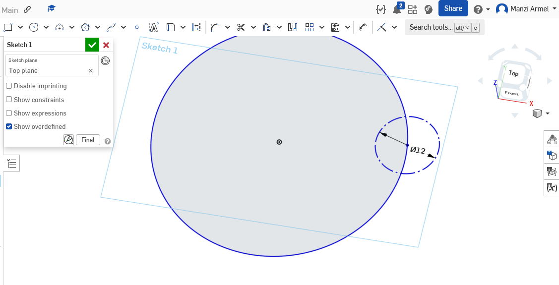
Starting the Sketch
Here's exactly how I set up my initial sketch:
-
Initial setup:
- Started in an empty Parts Studio
- Pressed 'S' as a shortcut to begin sketching
- Selected the front plane
- Used 'N' key for normal view
- Used 'E' to hide all planes for a cleaner workspace
-
Creating the base geometry:
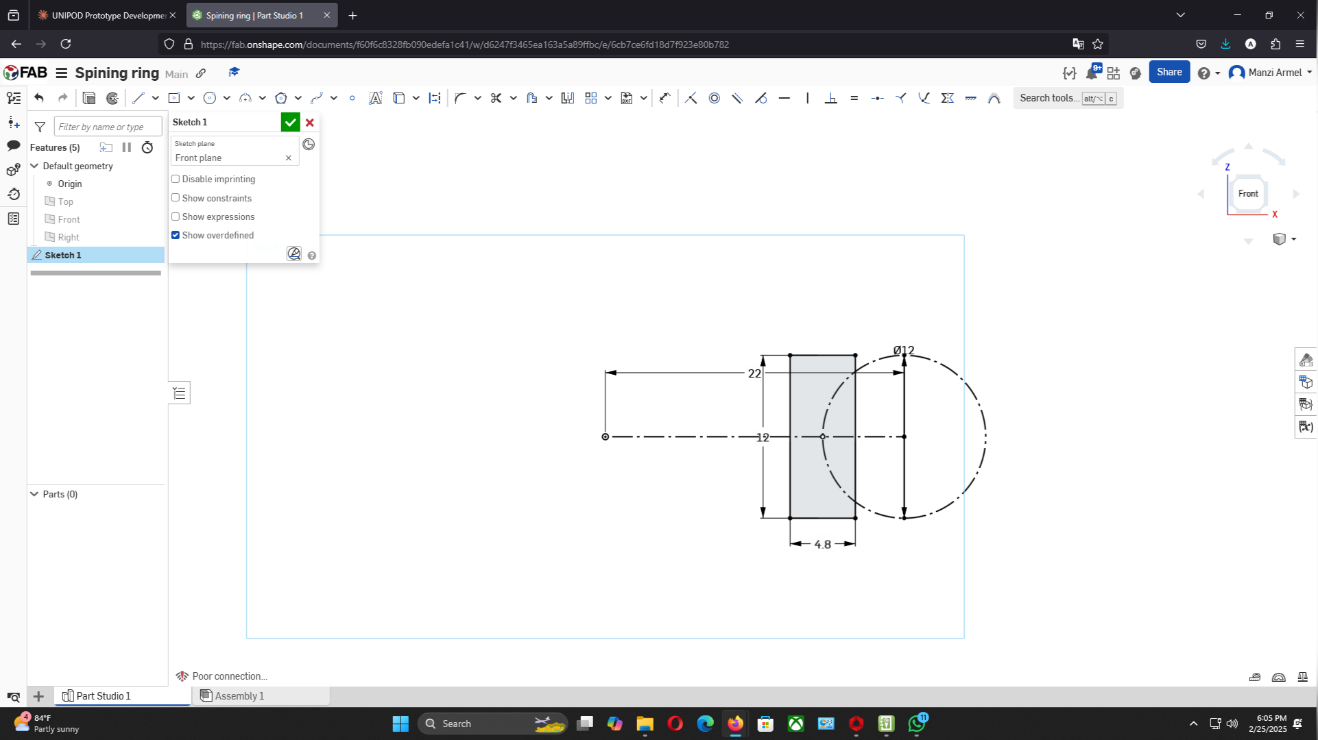
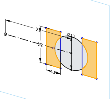
- Used 'L' and 'Q' to make a construction line from the origin
- Set construction line length to exactly 22mm
- Drew a circle with a precise 12mm diameter
- Added a vertical line for reference
- Used 'Shift+M' to create a midpoint relationship between the line and origin
-
Building the profile:
- Created a centerpoint rectangle
- Set dimensions to 4.8mm width and 12mm height
- Used 'i' key to make it coincident with the circle
- Applied mirror command to reflect the four lines using my reference line
-
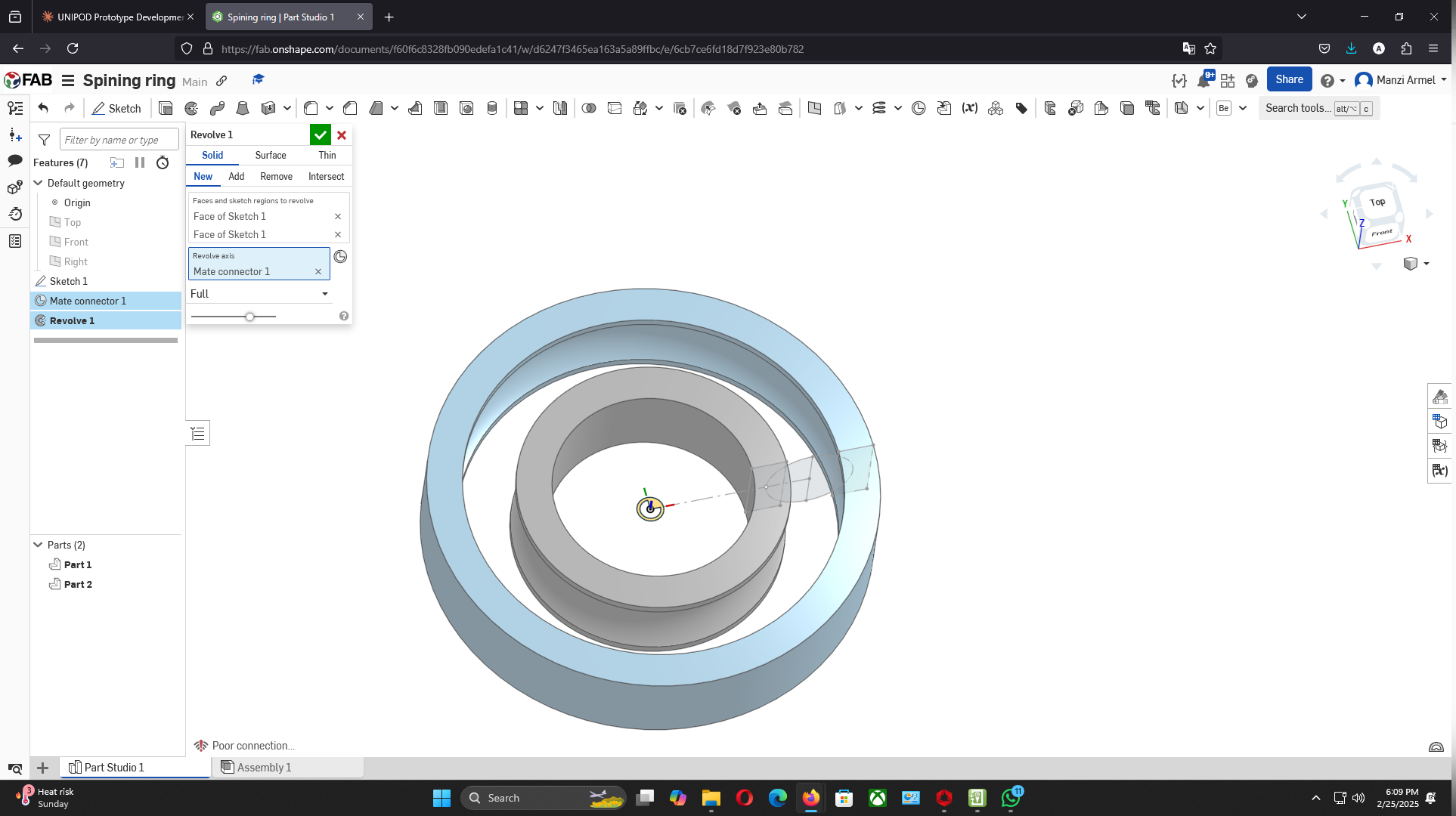
Setting up for revolution:
- Defined a mate connector at the origin with Z axis pointing up
- Made the sketch visible again
- Used the revolve command on both regions around the mate connector
-
Results of the revolution:
- Created three distinct parts in my Part Studio:
- Outer race (ring)
- Center/inner race
- Ball component
-
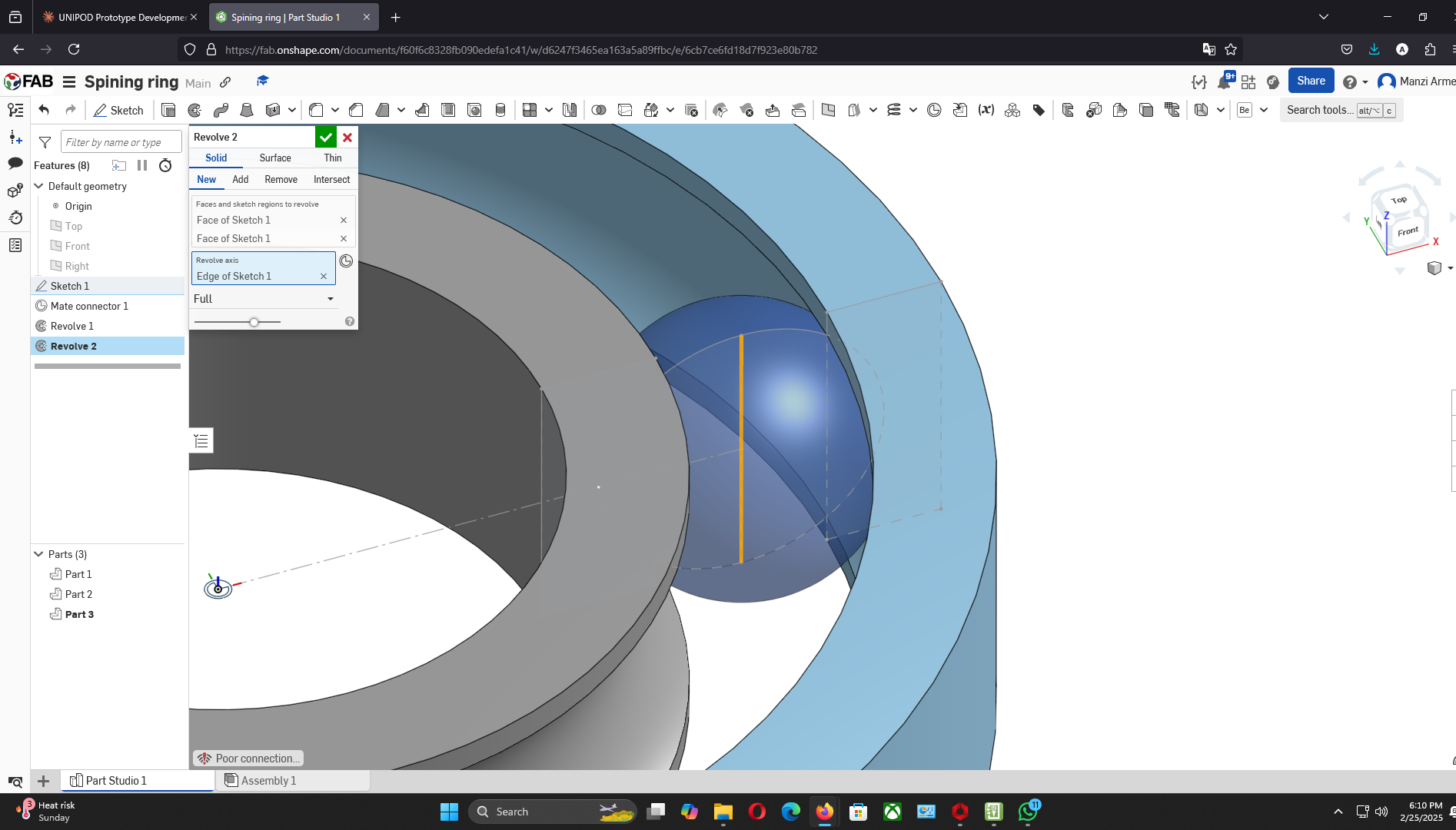
Color and transparency:
- Applied light gray appearance to races
- Adjusted transparency of two parts using the slider
- Made the ball orange for better visibility
-
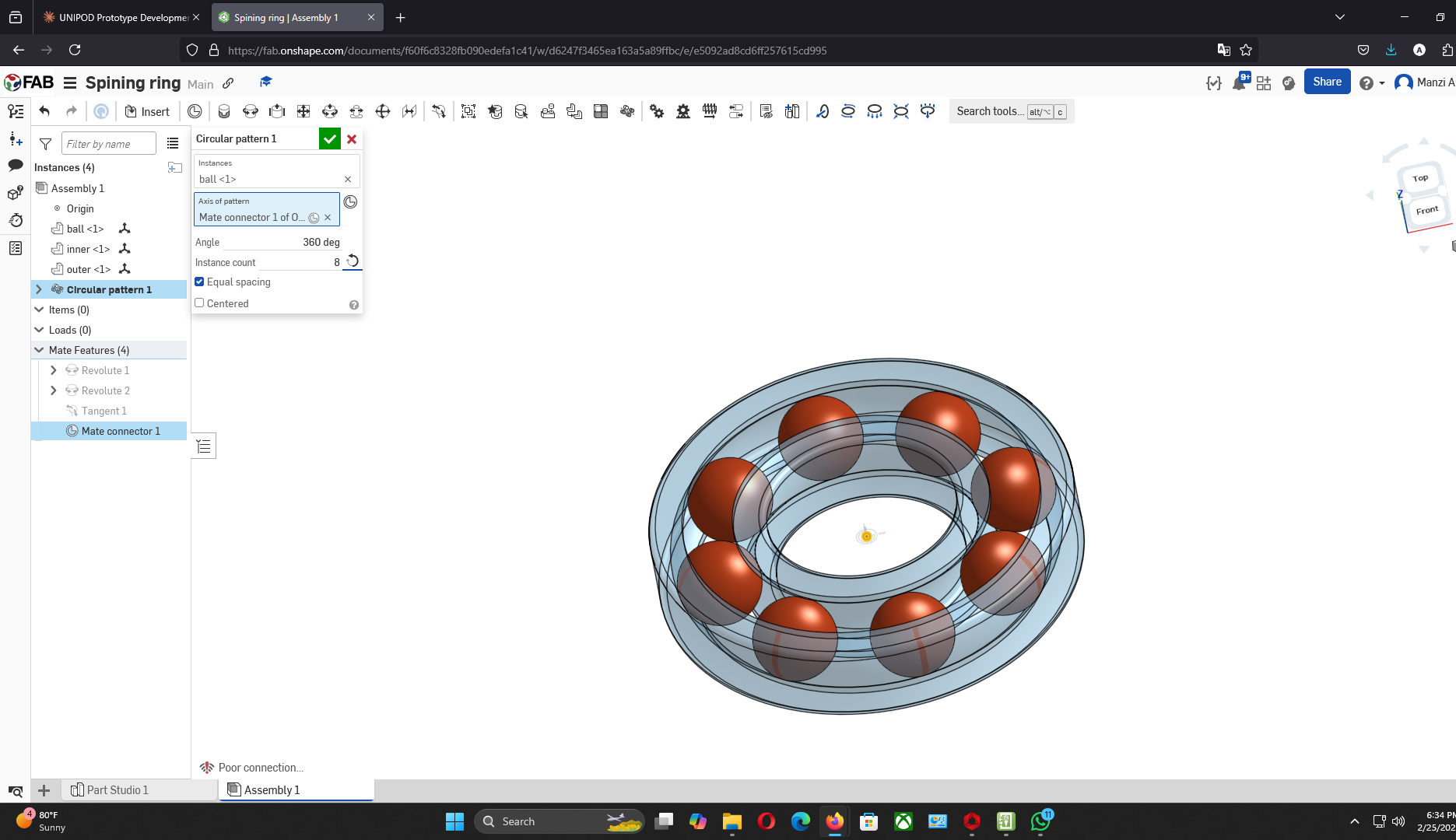
Setting up the pattern:
- Defined a mate connector at the origin
- Created an assembly circular pattern
- Selected the ball as the component to pattern
- Specified 8 instances around the axis
-
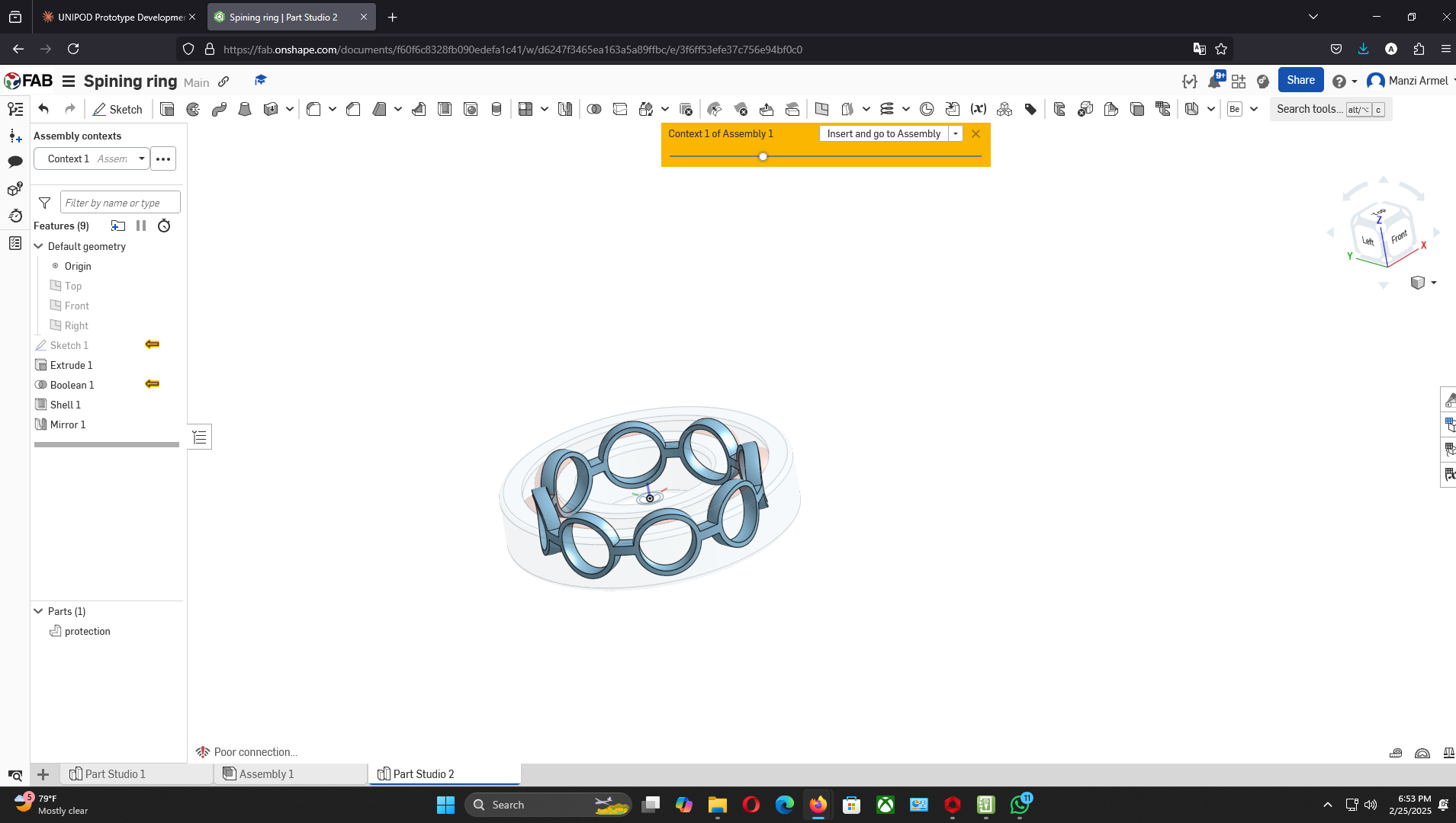
Starting the cage design:
- Used "Create Part Studio in Context" feature
- Selected the mate connector as origin
- Started a sketch on the top plane
- Used 'P' to hide planes for cleaner view
-
Creating the cage geometry:
- Used 'U' to project one ball silhouette to sketch
- Selected the circle and pressed 'Q' to convert to construction line
- Used 'B' to create circles connected to the center
- Extruded the circular edge with mid-plane option
- Set thickness to 3mm with 25mm extrusion
-
Finalizing the cage:
- Performed boolean operation to subtract balls from cage (kept tools)
- Applied shell command with 1mm thickness
- Removed three faces for proper structure
- Mirrored upper cage over the top plane
- Renamed part to "cage" and customized appearance
-
Inserting the cage:
- Inserted cage into the main assembly
- Created a group relation between cage and balls
-
Setting up motion:
- Hid the mate connector at the origin
- Selected the face of the cage
- Picked the mate connector from the origin
- Suppressed the tangent relationship (no longer needed)
- Used Revolute tool to animate the assembly
-
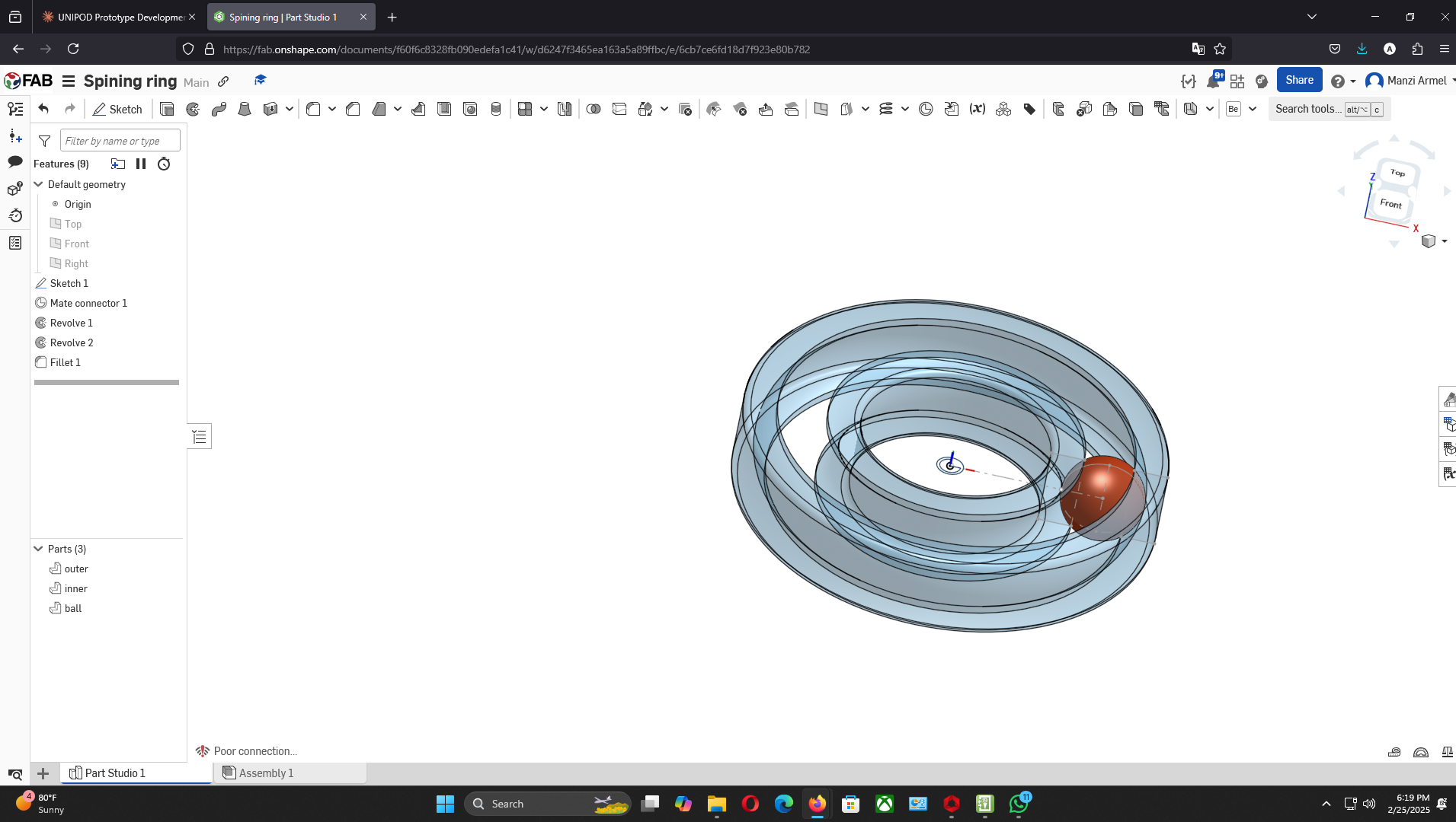
Adding fillets:
- Applied an other 1mm fillets to edges by selecting faces
- Ensured smooth transitions between surfaces
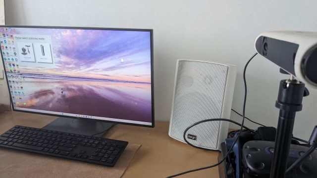
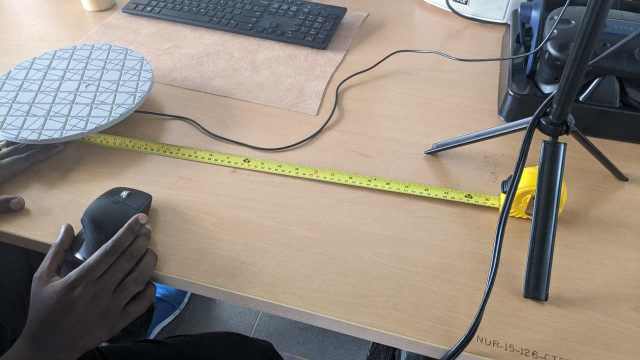
- Positioned the scanner on a stable tripod 45-60cm from the turntable
- Connected the scanner to the processing laptop via USB 3.0
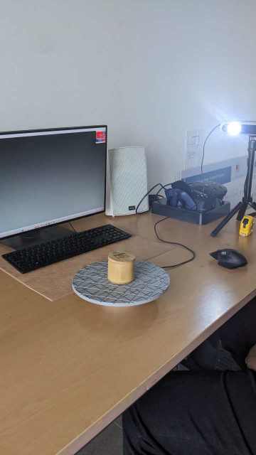
- Ensured consistent ambient lighting with minimal shadows
- Performed scanner warm-up for 15 minutes to stabilize the projector
- Positioned object at the center of the turntable
- Set turntable to rotate automatically at 15° increments (24 positions total)
- Configured scanner for medium resolution (0.1mm) capture
- Created an initial 360° scan set at central height position
- Repositioned scanner to capture top-down view and performed scan
- Repositioned scanner for bottom-up view and performed scan
- Performed targeted scans of complex features using manual scanner positioning
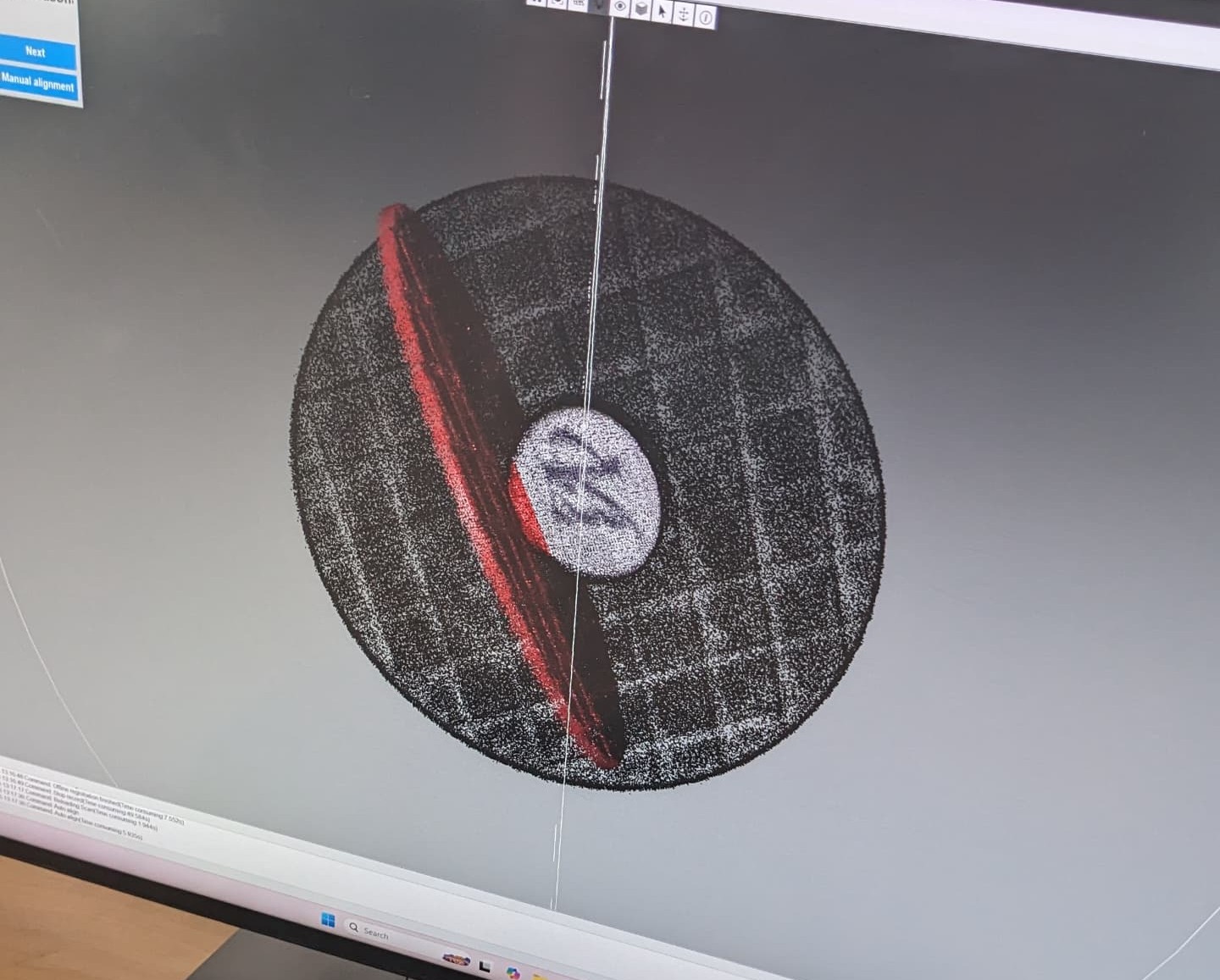
- Live preview window showing structured light pattern projection
- Point cloud development to identify coverage gaps
- Color-coded quality indicators (blue = good, red = poor quality)
- Scanner positioning feedback to maintain optimal distance
- Measured key dimensions of physical object and compared to digital model (achieved ±0.2mm accuracy)
- Generated cross-sections of the model to verify internal geometry
- Overlayed multiple scan iterations to identify consistency issues
- Performed a small-scale test print to verify printability
- ORGINAL File for 3d Pritining 3d Prining stl
- ORGINAL File for 3d scanner stl 3d scanned stl Result
Creating the 3D Components
Here's how I transformed the sketch into 3D components:
Adding Visual Style
Enhancing the appearance of the components:
Creating the Ball Pattern
Duplicating the ball in a circular pattern:
Building the Cage
Creating the component that holds the balls in position:
Note: In real bearings, there are two sides of the cage held by pins - might try implementing that approach later.
Final Assembly and Animation
Completing the assembly and making it move:
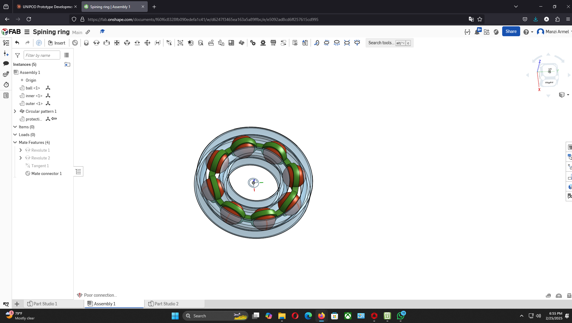
Animation of the completed ball bearing assembly in motion
Now to 3d print
Am using a CR200B Crearity 3d printer
I started by extrating the stl file from the final assembly
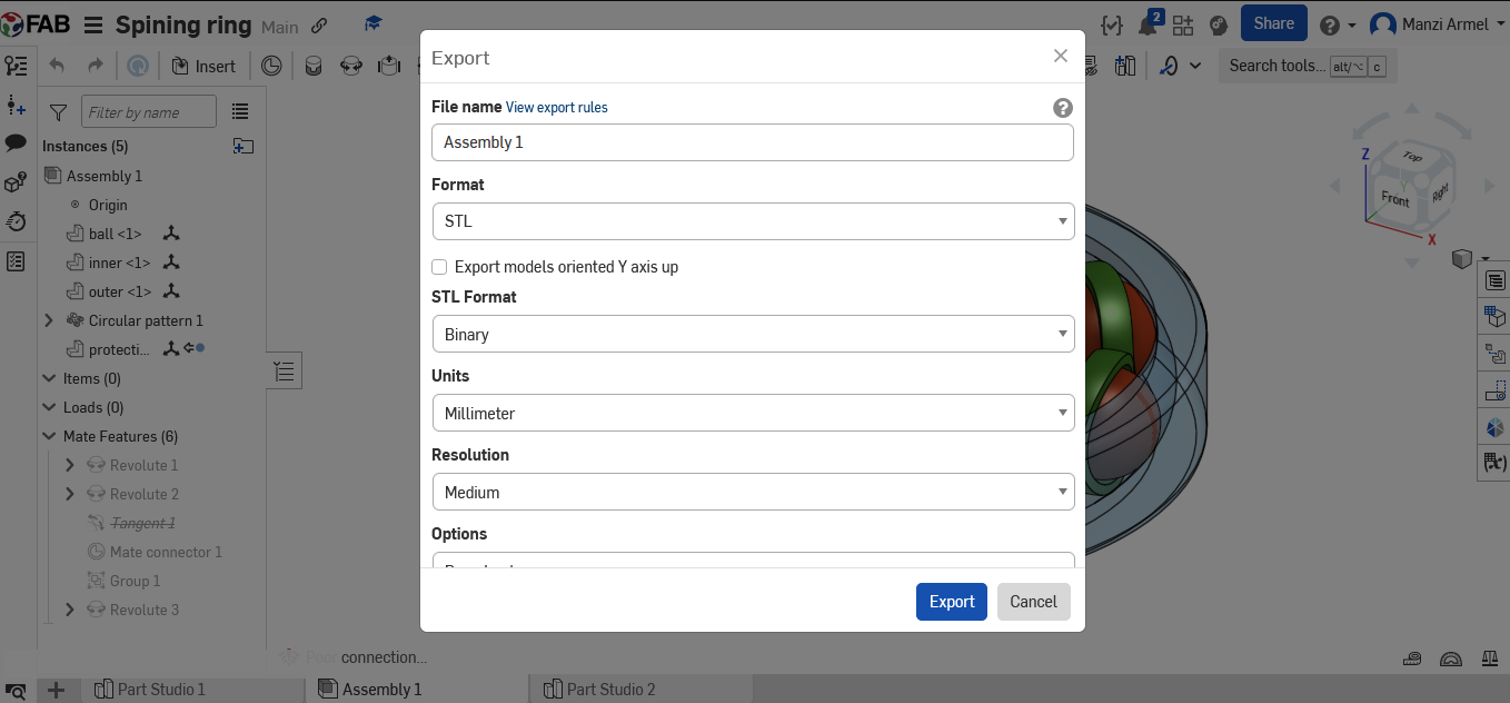
I used the Creality Slicer 4.8.2 to slice the design
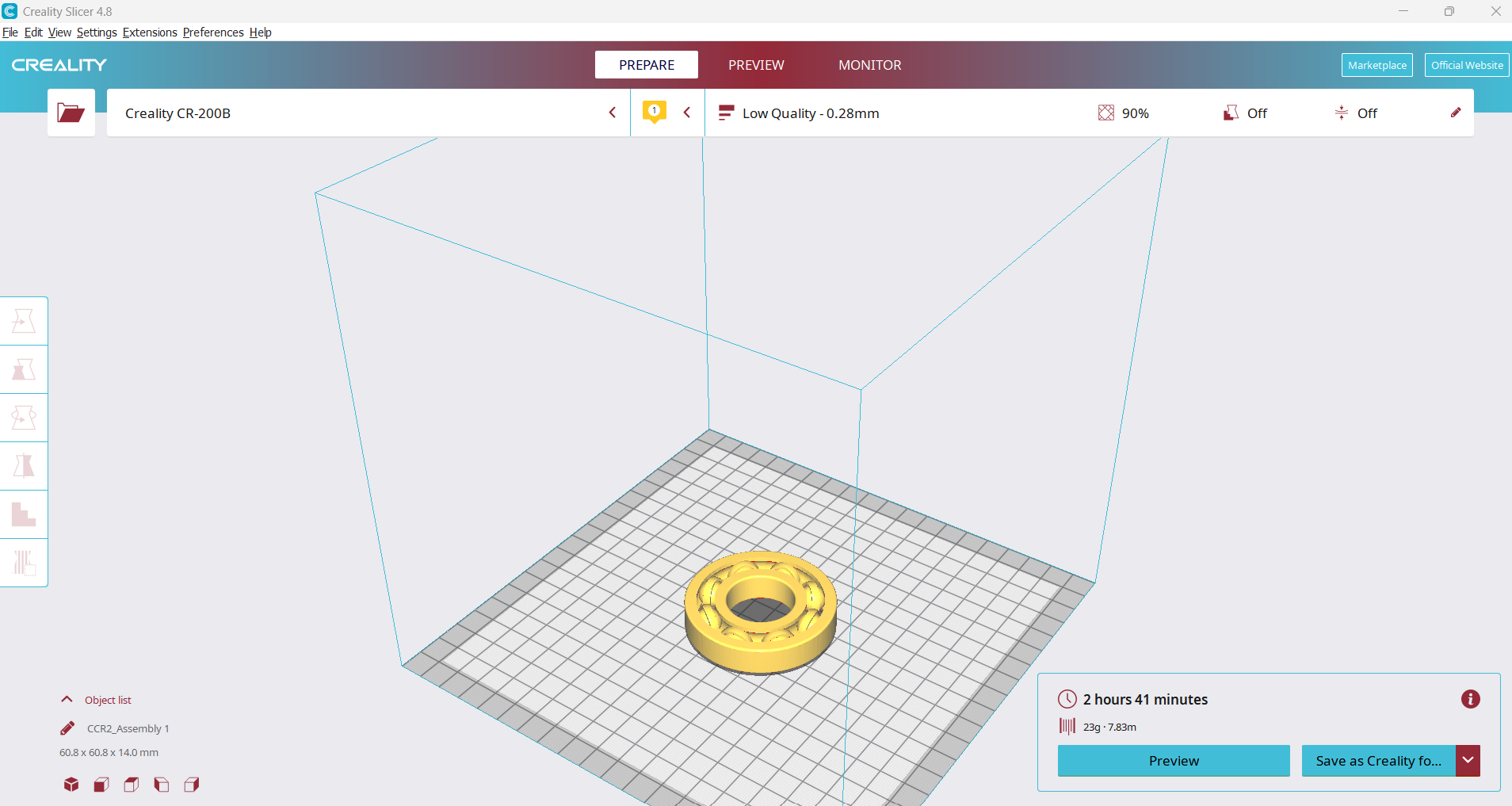
1st Printing
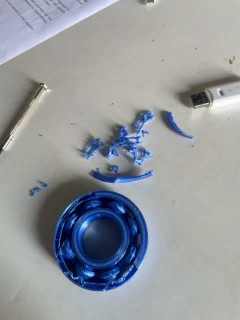
Failed because the ball was attached with the cage and it was not moving so i had to edit the sizes
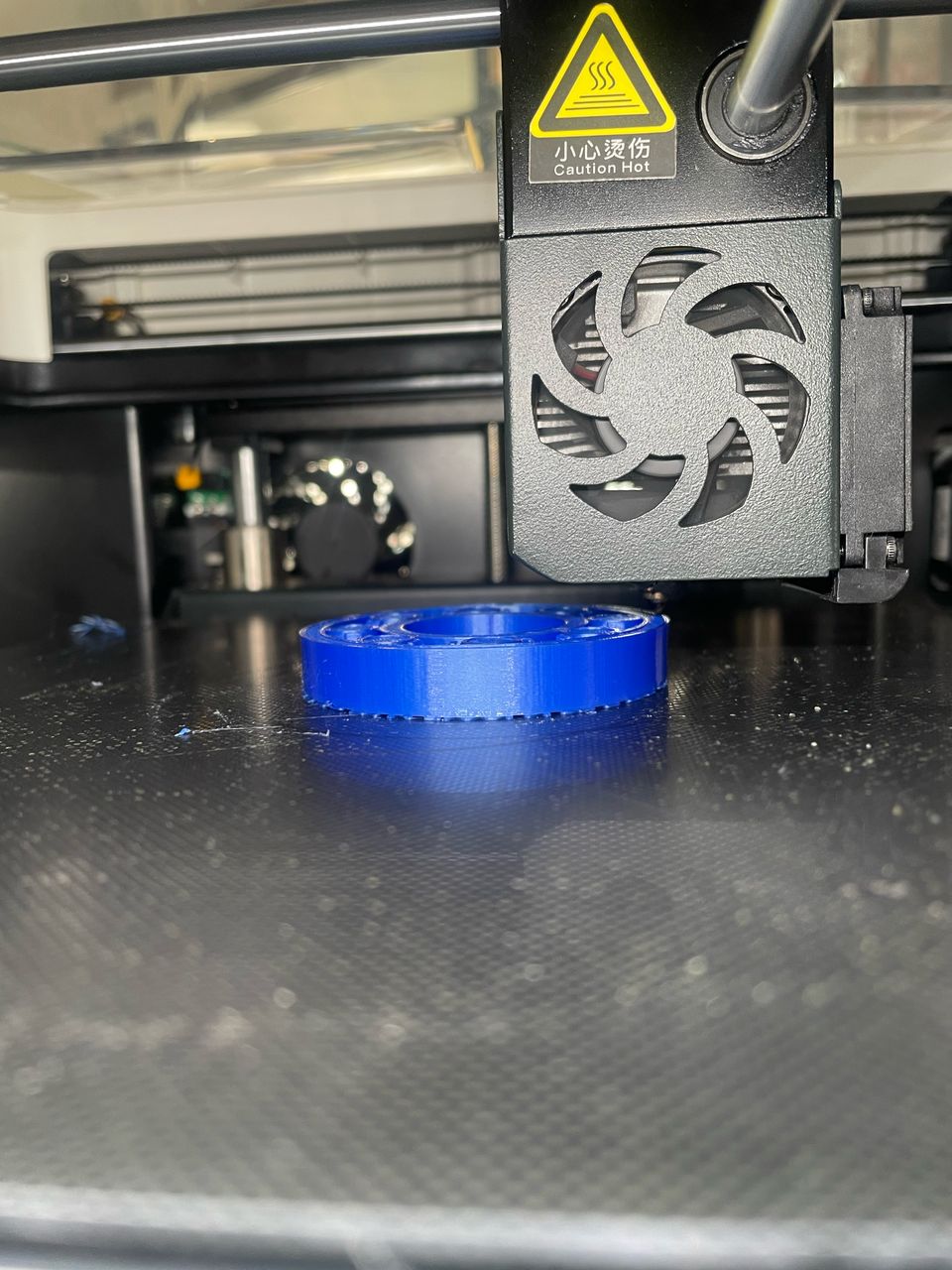
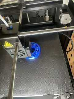
the second printing look promising
hey it is working but i will need add more space for it to move smoothly
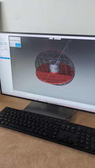
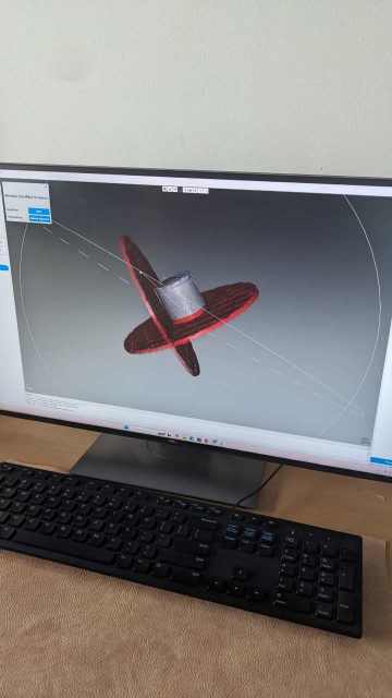
My 3d scanner Printing
for the 3d scanning i used the Scanner CR-Scan 01 Creality
started by the opening the software CR studio Product Asset Download
Equipment Setup
I used a structured light 3D scanner with the following setup procedure:
Calibration Process
Calibration was crucial for accurate measurements:
Scanning Workflow
I followed this optimized scanning sequence:
Real-time Monitoring
During scanning, I constantly monitored:
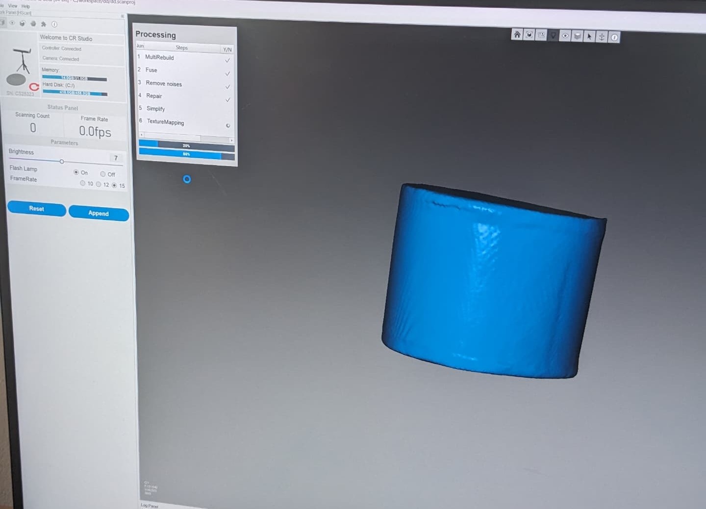
Post-Processing
After completing all scans, I processed the data using the following steps:
Quality Verification
I validated the scan quality using multiple methods:
| Quality Metric | Target Value | Achieved Value |
|---|---|---|
| Resolution | 0.1mm | 0.08mm |
| Dimensional Accuracy | ±0.3mm | ±0.2mm |
| Surface Completeness | 95% | 98% |
| File Size Optimization | Under 100MB | 78MB |