This week we needed to send a message between two boards. Sounds simple enough, right?
Well, it took us a few tries to get it working properly, but we figured it out in the end!
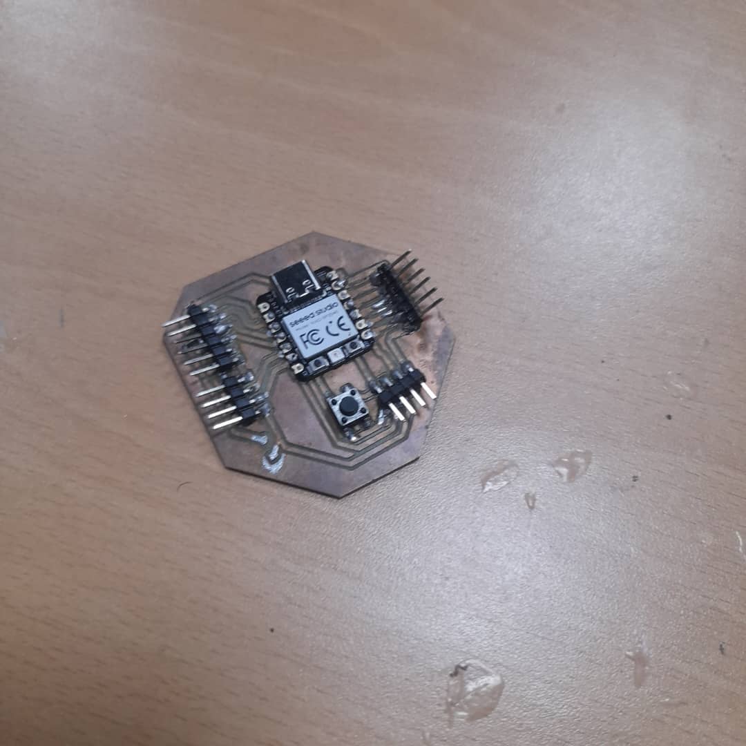
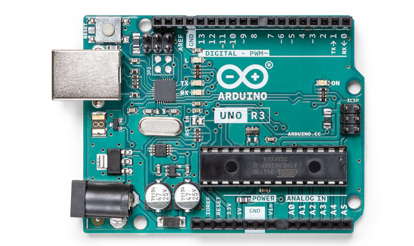
We wanted to make something pretty cool - press a button on one board and have LED light up on an other board. The idea was to use two XIAO RP2040 board and Arduino uno board and make them communicate using serial communication (UART). We thought this would be easier than trying to do wireless stuff, and honestly, we were right!
Instead of going with WiFi or Bluetooth (which seemed complicated), we decided to use good old UART serial communication. It's basically like having a conversation between two boards using just two wires. Pretty neat actually!
Think of it like walkie-talkies, but with wires:
We used our custom XIAO RP2040 board from previous weeks and the existing Arduino uno.
| Board 1 Pin | Board 2 Pin | What it does |
|---|---|---|
| TX (Pin 0) | RX (Pin 1) | Board 1 talks to Board 2 |
| RX (Pin 1) | TX (Pin 0) | Board 2 talks back to Board 1 |
| GND | GND | Shared ground (super important!) |
| LED on 13 | LED on 13 | LED that light up |
| Button on D3 | Button on D3 | Button to press |
The programming part was actually pretty straightforward once we figured out the logic. Both boards run almost the same code, just with tiny differences.
void setup() {
  Serial1.begin(9600);
  pinMode(D2, INPUT_PULLUP);
}

void loop() {
  if (digitalRead(D2) == LOW) {
    Serial1.write('a');  // Send trigger signal
    digitalWrite(LED_BUILTIN, HIGH);  // Local LED on
    delay(20);  // Debounce
  } else {
    digitalWrite(LED_BUILTIN, LOW);
  }
}
#includeSoftwareSerial mySerial(10, 11); // RX on 10 void setup() { pinMode(13, OUTPUT); mySerial.begin(9600); } void loop() { if (mySerial.available() && mySerial.read() == 'a') { digitalWrite(13, !digitalRead(13)); // Toggle LED } }
Let's be honest - it didn't work the first time. We had to debug a few things:
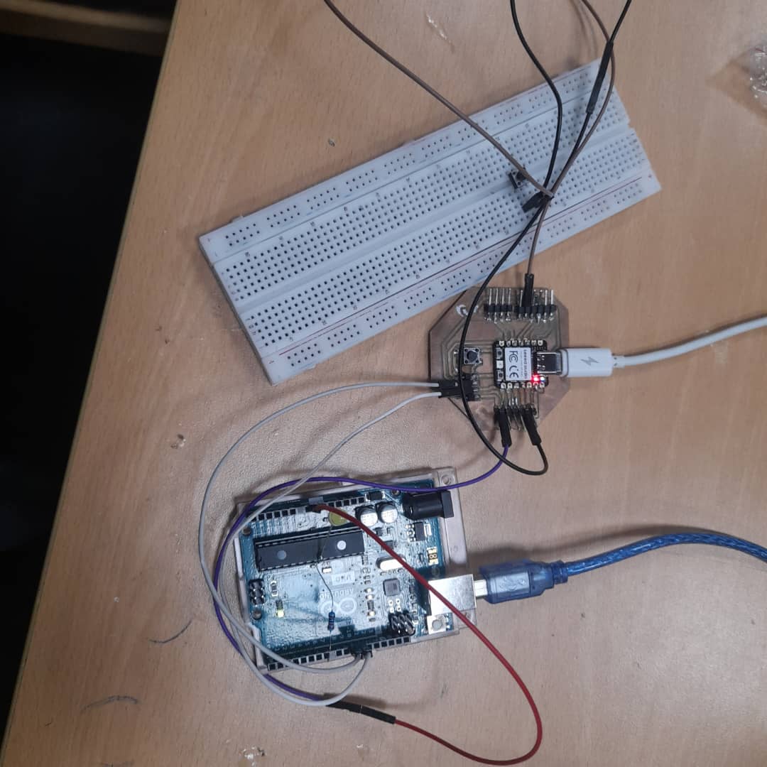
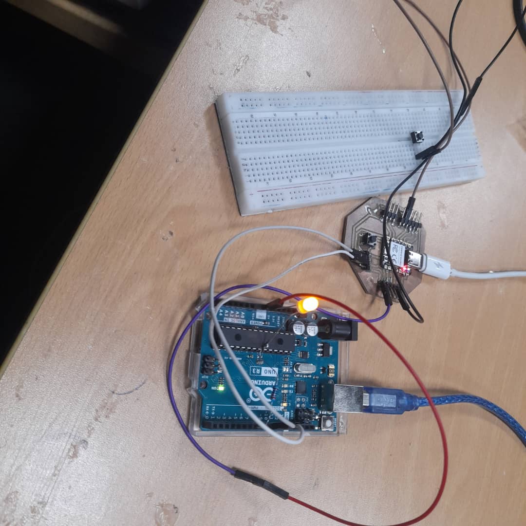
When we finally got it working, it was pretty satisfying. Press one button on the other board, the LED light up which is connected to the other board. The communication was fast and reliable.
| Communication Method | Good stuff | Not so good stuff |
|---|---|---|
| UART (what we used) | Simple, reliable, fast, low power | Need wires, short distance only |
| ESP-NOW | No wires, works far apart | Way more complicated, need ESP32 boards |
| I2C | Can connect many devices | More complex addressing system |
| SPI | Super fast | Need more wires, overkill for our project |
This project taught us a lot about communication between microcontrollers:
Overall, this was a really fun project! We managed to get two boards talking to each other using serial communication. It might not be as fancy as wireless, but it's reliable and easy to understand. Plus, seeing both LEDs light up when you press one button never gets old!
Pro tip: Always check your wiring twice before blaming the code. We learned this the hard way!