- Week 1 : Project Management
- Week 2 : Computer-aided
- Week 3 : Computer Controlled Cutting
- Week 4 : Embedded Programming
- Week 5 :3D Scanning and Printing
- Week 6 : Electronic Design
- Week 7 : Computer Controlled Machining
- Week 8 : Electronics Production
- Week 9 : Input Devices
- Week 10 : Output Devices
- Week 11 : Networking and Communication
- Week 12 : Mechanical Design and Machine Design
- Week 14 : Molding and Casting
- Week 15 : Interface and Application Programming
- Week 16 : System Integeration
- Week 17 : Wildcard Week
- Week 18 : Applications and Implications, Project Development
- Week 19 : Invention, Intellectual property and Income
- Week 20 : FInal Project Requirements
Week 9:Input Devices
This week describes my understanding of how to use Input Devices. It also includes how to generate an analog output (PWM) using pin 9, how to use an oscilloscope and multimeter for analysis, and how to integrate different sesnor with the microcontroller.
For More About group AssignmentInterpret a Signal
We generate an analog output (PWM) using pin 9. A LED is connected to see the signal effect, and the oscilloscope and multimeter are used for analysis.
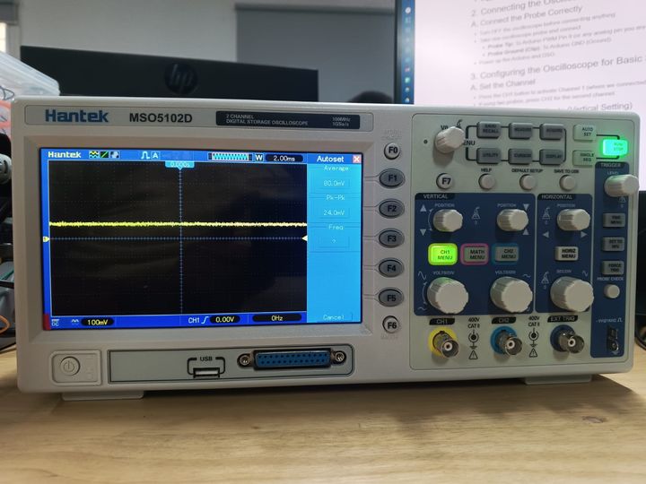
1. Understanding DSO Components
- Power Button: Turns the DSO ON/OFF.
- Display Screen: Shows the waveform.
- Probe Inputs (CH1, CH2): Connect the oscilloscope probes here.
- Time/Div Knob: Adjusts the time scale (horizontal axis).
- Volts/Div Knob: Adjusts the voltage scale (vertical axis).
- Trigger Controls: Helps stabilize the waveform.
2. Connecting the Oscilloscope to Arduino
A. Connect the Probe Correctly
- Turn OFF the oscilloscope before connecting anything.
- Take one oscilloscope probe and connect:
- Probe Tip: To Arduino PWM Pin 9 (or any analog pin you are testing).
- Probe Ground (Clip): To Arduino GND (Ground).
- Power up the Arduino and DSO.
3. Configuring the Oscilloscope for Basic Signal Viewing
A. Set the Channel
- Press the CH1 button to activate Channel 1 (where we connected the probe).
- If using two probes, press CH2 for the second channel.
B. Adjust the Voltage Scale (Vertical Setting)
- Use the Volts/Div knob to set the voltage range.
- Start with 1V/div and increase if needed.
- For a 5V Arduino signal, set it around 2V/div for better viewing.
C. Adjust the Time Scale (Horizontal Setting)
- Use the Time/Div knob to set the time range.
- If measuring PWM signals (~500Hz), start with 1ms/div.
- If measuring fast signals (above 1kHz), use 100µs/div.
D. Set the Trigger for a Stable Display
- Press the Trigger Menu and set:
- Mode: Edge
- Source: CH1
- Slope: Rising Edge
- Level: Adjust until the waveform stabilizes
4. Running the Oscilloscope & Viewing the Waveform
- Press AUTOSET (if available) to let the DSO automatically adjust settings.
- If AUTOSET doesn’t work well, manually tweak Volts/Div and Time/Div.
- Observe the waveform:
- If using PWM output, you should see a square wave.
- If using an analog sensor, the waveform may look more irregular.
- Use Cursors or Measurements (if your DSO has them) to check signal values.
5. Capturing & Analyzing the Waveform
- If your oscilloscope has a Save function, take a screenshot of the waveform.
- Compare the output with the expected Arduino signal.
- Adjust your Arduino code if needed to modify the signal.
                void setup() {
                pinMode(9, OUTPUT);
                }

                void loop() {
                for (int u = 0; u < 255; u++){
                    analogWrite(9, u);
                    delay(50);
                }
                }
Video Demonstration
Joystick Module
The Joystick Module consists of two potentiometers, each controlling an axis (X and Y).
Reading Joystick Module
Connect the joystick to Arduino: A0 and A1 for analog readings, pin 2 for the button.
                    int x_Pin = A0;
                    int y_Pin = A1;
                    int button_Pin = 2;

                    void setup(){
                        Serial.begin(9600);
                        pinMode(button_Pin, INPUT_PULLUP);
                   }

                    void loop(){
                        Serial.print("X: "); Serial.print(analogRead(x_Pin));
                        erial.print("\tY: "); Serial.print(analogRead(y_Pin));
                        Serial.print("\tButton: "); Serial.println(digitalRead(button_Pin));
                    delay(100);
                    }
Joystick Axis Values
| Axis X | Axis Y | |
|---|---|---|
| Up | 1023 | 527 |
| Down | 0 | 527 |
| Right | 512 | 1023 |
| Left | 512 | 0 |
| Center | 512 | 527 |
Video Demonstration
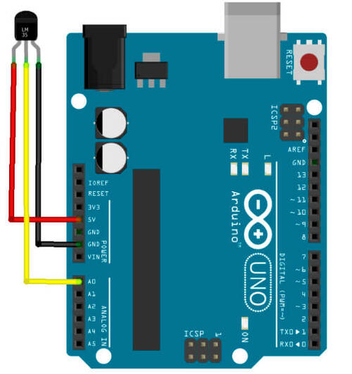
Temperature Sensor LM35
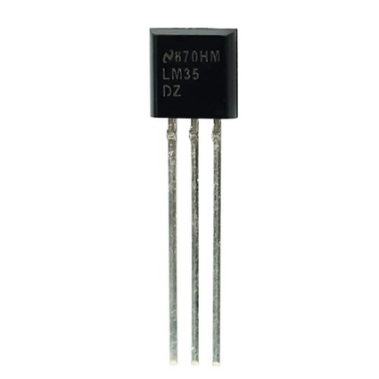
The LM35 is an analog temperature sensor with an output range of 0V to 1.5V.
                float temp = 0.0;
                int temp_Pin = 0;

                void setup(){
                    Serial.begin(9600);
                }
                void loop(){
                    temp = analogRead(temp_Pin);
                    Serial.print("temperature: ");
                    Serial.println(temp);
                    delay(100);
                }
Converting to Celsius
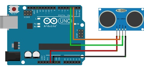
float temp_C = (5.0 * temp * 100.0) / 1024.0;Ultrasonic Sensor HC-SR04
The HC-SR04 sensor calculates distance using ultrasonic waves.
            const int Trig = 2;
            const int Echo = 3;
            float tim = 0.0;
            float dist = 0.0;

            void setup(){
                Serial.begin(9600);
                pinMode(Trig, OUTPUT);
                pinMode(Echo, INPUT);
                digitalWrite(Trig, LOW);
            }

            void loop(){
                digitalWrite(Trig, HIGH);
                delayMicroseconds(10);
                digitalWrite(Trig, LOW);
                tim = pulseIn(Echo, HIGH);
                dist = tim / 59.0;
                Serial.print("Distance: ");
                Serial.print(dist);
                Serial.println(" cm");
                delay(100);
            }
Lets get into actual Work
For this week we have to do a board attached with Microcontroller and then work on the
As we have worked on the previous weeks for PCB Design and Electronics Production. we are gonna repeat the same process for the Board production
KiCAD Works
Initially we're setting up the process for the Design as we're gonna design the product for Joystick Input, SDA, SCL ports and then Servomotor ports
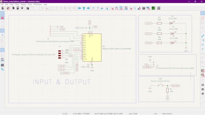
Schematic Design
Initially designed up the Kicad Schematic for the Board that we are gonna design
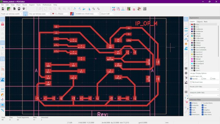
PCB Design
Now we gonna change that into PCB design using PCB Editor
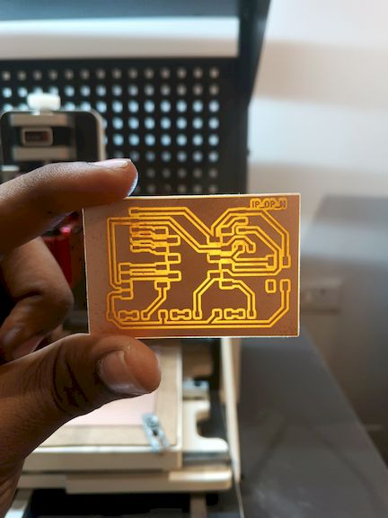
PCB Milling
After Designing the Board exported it as nc file from the MoDS CE and imported it to Wegster CNC for milling and afterwards get that final Product is
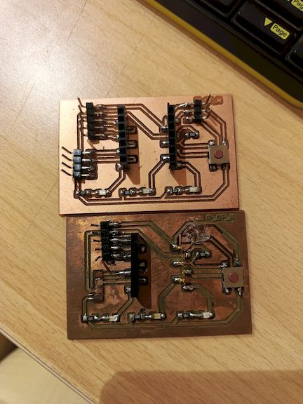
Version 1 & Version 2 of the Board
The Problem is due to the form of greenish layer on the Coppper Board and the other one is well cleaned and secured with mineral oil after fabrication
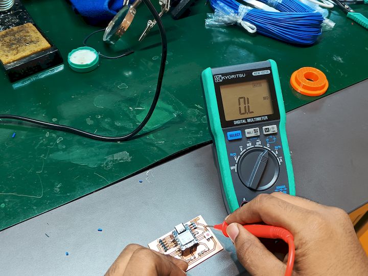
Blunders happened during making Soldering
Intially I have soldered try to turn board it doesn't show any output and then I came to know the solder trace for the GND wasn't done at best
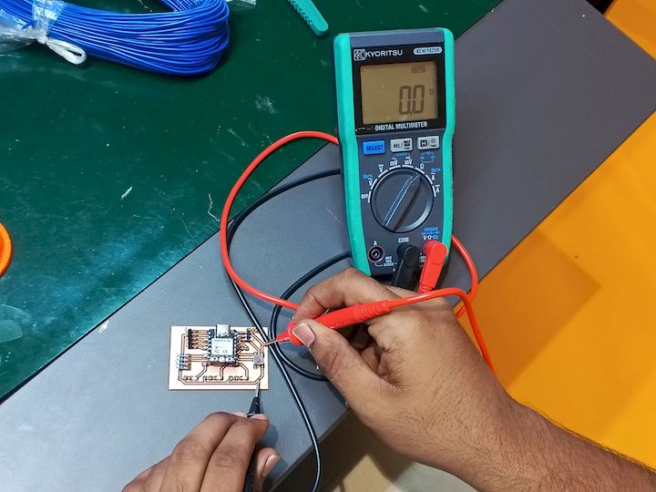
Making things ready for showing output
Now we get the solder and make up the Board and next we are gonna add the joystick to our microcontroller and afterwards showing the Graph out in Serial Plotter in arduino
Joystick Interface Code Explanation
            #define VRX_PIN 2   // A0
            #define VRY_PIN 3   // A1
            #define SW_PIN  0   // Digital button

            void setup() {
                Serial.begin(115200);
                pinMode(SW_PIN, INPUT_PULLUP); // Joystick button is active LOW
            }

            void loop() {
                int xValue = analogRead(VRX_PIN);
                int yValue = analogRead(VRY_PIN);
                int swState = digitalRead(SW_PIN);

            // Format for Serial Plotter: label:value, label:value
                Serial.print("X:");
                Serial.print(xValue);
                Serial.print(",Y:");
                Serial.print(yValue);
                Serial.print(",SW:");
                Serial.println(swState == LOW ? 0 : 4095); // show pressed/released as 0 or 4095

                delay(50); // smoother graph
            }
Pin Definitions
#define VRX_PIN 2: Assigns pin 2 to read X-axis analog values.#define VRY_PIN 3: Assigns pin 3 to read Y-axis analog values.#define SW_PIN 0: Assigns pin 0 to read joystick button state.
Setup Function
Serial.begin(115200);: Begins serial communication for plotting or debugging.pinMode(SW_PIN, INPUT_PULLUP);: Sets the button pin as input with an internal pull-up resistor.
Loop Function
int xValue = analogRead(VRX_PIN);: Reads and stores X-axis value.int yValue = analogRead(VRY_PIN);: Reads and stores Y-axis value.int swState = digitalRead(SW_PIN);: Reads the joystick button state (pressed/released).
Serial Output Formatting
Serial.print("X:"): Labels the X value for plotting.Serial.print(xValue): Prints the X-axis value.Serial.print(",Y:"): Adds Y-axis label.Serial.print(yValue): Prints Y-axis value.Serial.print(",SW:"): Adds switch label.Serial.println(swState == LOW ? 0 : 4095);: Converts button state to 0 or 4095 for Serial Plotter graph scaling.
Delay
delay(50);: Adds a 50ms delay for smoother plotting without excessive data refresh.
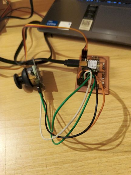
Hero Shot
Learning Summary
- Learned about the basics of Arduino and its components.
- Understood about the Xiao - Seeed Studio Esp32C3
- Learned how to use the LiquidCrystal library to control an LCD screen.
- Implemented a simple timer using the LCD screen.
- Interfacing Joystick with actually fabricated PCB Board
Download the Files
That’s all for now!