- Week 1 : Project Management
- Week 2 : Computer-aided
- Week 3 : Computer Controlled Cutting
- Week 4 : Embedded Programming
- Week 5 :3D Scanning and Printing
- Week 6 : Electronic Design
- Week 7 : Computer Controlled Machining
- Week 8 : Electronics Production
- Week 9 : Input Devices
- Week 10 : Output Devices
- Week 11 : Networking and Communication
- Week 12 : Mechanical Design and Machine Design
- Week 14 : Molding and Casting
- Week 15 : Interface and Application Programming
- Week 16 : System Integeration
- Week 17 : Wildcard Week
- Week 18 : Applications and Implications, Project Development
- Week 19 : Invention, Intellectual property and Income
- Week 20 : FInal Project Requirements
Week 5: 3D Printing and Scanning
Objectives of the Week
Group Assignment
Individual Assignment
Group Assignment Contribution
In this Week, I have Contributed in the understanding characteristics of My 3D Printer
Characteristics of my 3D Printer
In our Lab we have two Printers one is from Creality and another one is from Flash Forge
For more about Group AssignmentAbout FlashForge Creator 3 Pro
The FlashForge Creator 3 Pro is a professional IDEX (Independent Dual Extruder) 3D printer, allowing dual-material and multi-color printing. It has a 300°C high-temperature extruder, enabling compatibility with a wide range of filaments like PLA, ABS, PETG, PC, and Nylon. The heated flexible build plate improves adhesion and makes print removal easy. With an enclosed chamber, it maintains stable temperatures for better print quality. The active leveling system ensures precise calibration. It features Wi-Fi, USB, and Ethernet connectivity for remote operation. It cost comes around Rs. 2L
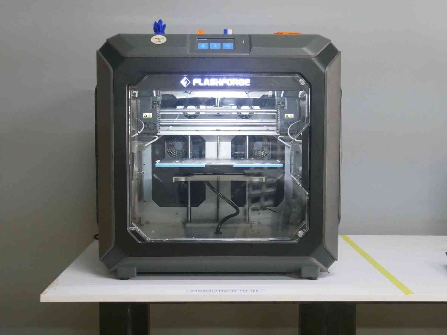
About FlashForge Creator 3 Pro
| Feature | Specification |
|---|---|
| Printing Technology | Fused Filament Fabrication (FFF) |
| Build Volume | 300 x 250 x 200 mm |
| Layer Resolution | 0.05 - 0.4 mm |
| Nozzle Diameter | 0.4 mm (Standard) |
| Printing Speed | ≤ 150 mm/s |
| Filament Diameter | 1.75 mm |
| Extruder Type | Independent Dual Extruders (IDEX) |
| Compatible Materials | PLA, ABS, PETG, TPU, PVA, Nylon, Carbon Fiber |
| Heated Bed | Yes (Max Temp: 120°C) |
| Nozzle Temperature | Max 320°C |
| Enclosure | Fully enclosed for temperature stability |
| Connectivity | USB, Wi-Fi, Ethernet |
| Power Supply | 24V / 500W |
| Display | 4.3-inch Touchscreen |
| Supported File Formats | STL, OBJ, 3MF, G-code |
| Compatible Software | FlashPrint, Simplify3D, Cura |
| Weight | 40 kg |
Designing the 3D Printed Object
The model was designed in Fusion 360. The objective was to create a hollow interconnected pipe structure that could demonstrate the advantages of additive manufacturing. The geometry contains internal connections and curved paths that would be difficult to manufacture using conventional subtractive processes.
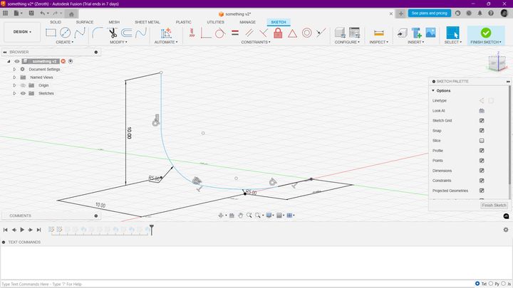
Figure 1: Creating the initial sketch profile in Fusion 360.
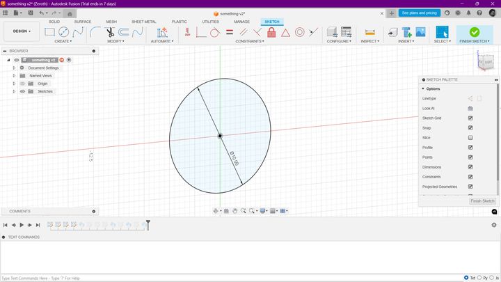
Figure 2: Creating the circular profile for the sweep operation.
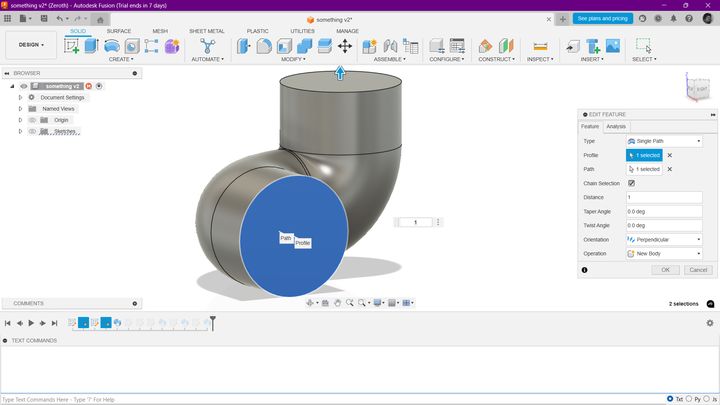
Figure 3: Generating the hollow pipe using the sweep feature.
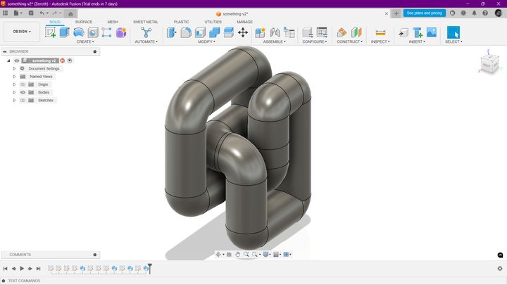
Figure 4: Repeating the sweep operation in multiple directions.
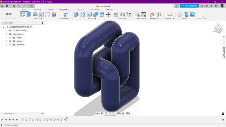
Figure 5: Final rendered model with appearance modifications.
Why this Model Cannot be Easily Manufactured Subtractively?
The object contains multiple interconnected internal channels and curved geometries. Manufacturing such a structure using conventional subtractive machining would require several setups and specialized tooling. Some internal features are inaccessible to cutting tools, making the geometry difficult or impossible to produce using traditional machining methods. Therefore, additive manufacturing is the most suitable fabrication process for this design.
Creality Slicer 4.8.2
After completing the CAD design, the STL file was imported into Creality Slicer 4.8.2. Slicing software converts the 3D model into machine-readable G-code and allows configuration of print settings such as layer height, infill, supports, and print speed.
Figure 6: Creality Slicer 4.8.2 software interface.
We selected the Creality Smart CR-10 Pro printer profile to match the build volume and machine specifications.
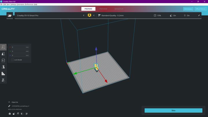
Figure 7: Importing the STL model into Creality Slicer.
Scaling and Rotating the Mesh
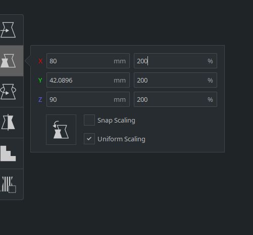
Figure 8: Initial model placement.
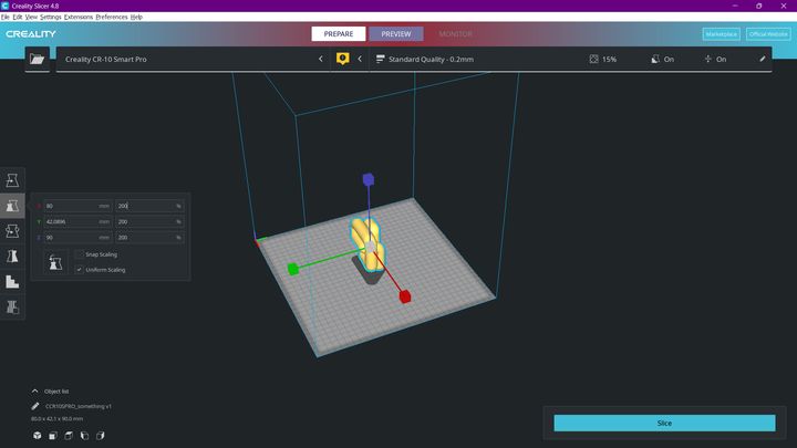
Figure 9: Scaling the model.
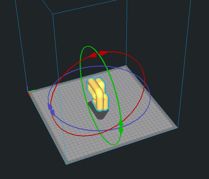
Figure 10: Rotating the model.
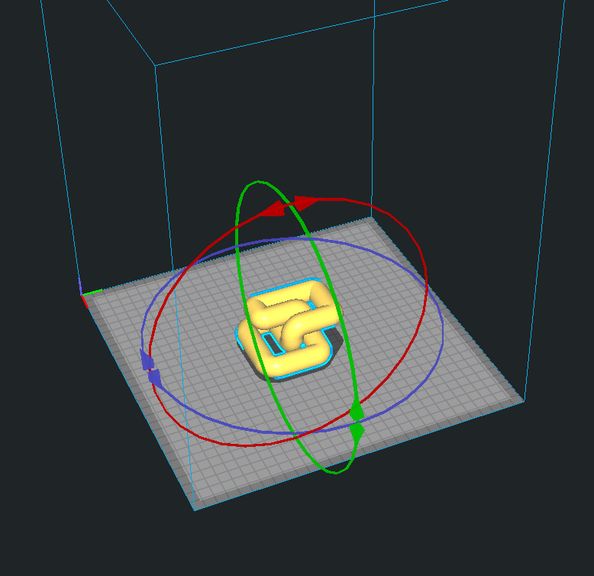
Figure 11: Final orientation before slicing.
Print Configuration and Support Settings
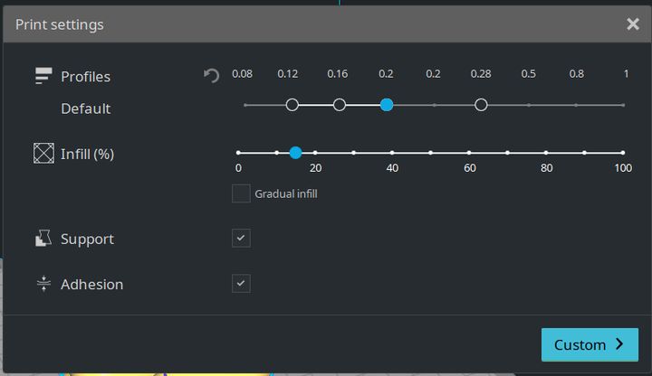
Figure 12: Layer and print settings.
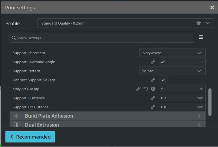
Figure 13: Support generation settings.
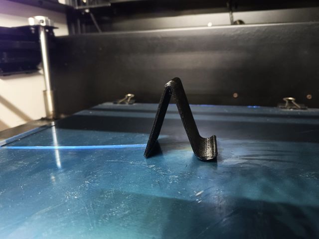
Figure 14: Slicing preview.
Exporting G-Code
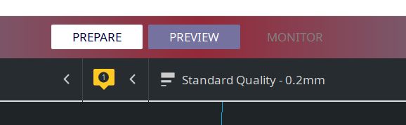
Figure 15: Generating G-code.
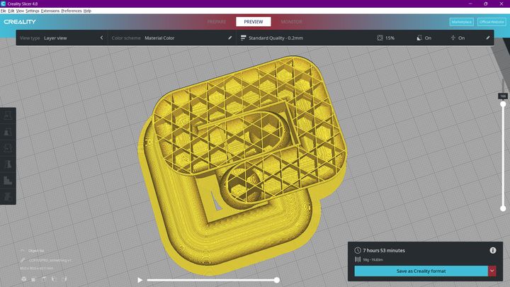
Figure 16: Exporting the final G-code file.
Machine Setup and Printing
The object was printed using PLA filament. The following parameters were configured before starting the print:
- Nozzle Temperature: 210°C – 220°C
- Bed Temperature: 60°C
- Material: PLA
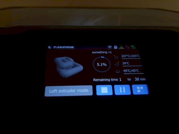
Figure 17: Printer setup and parameter verification.
Printing Process
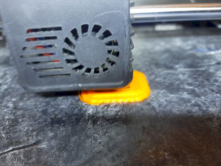
Figure 18: Initial layer deposition.
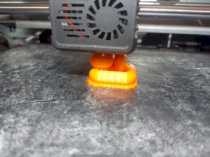
Figure 19: Printing progress.
Final 3D Printed Object
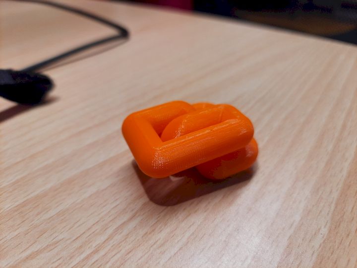
Figure 20: Completed printed object.
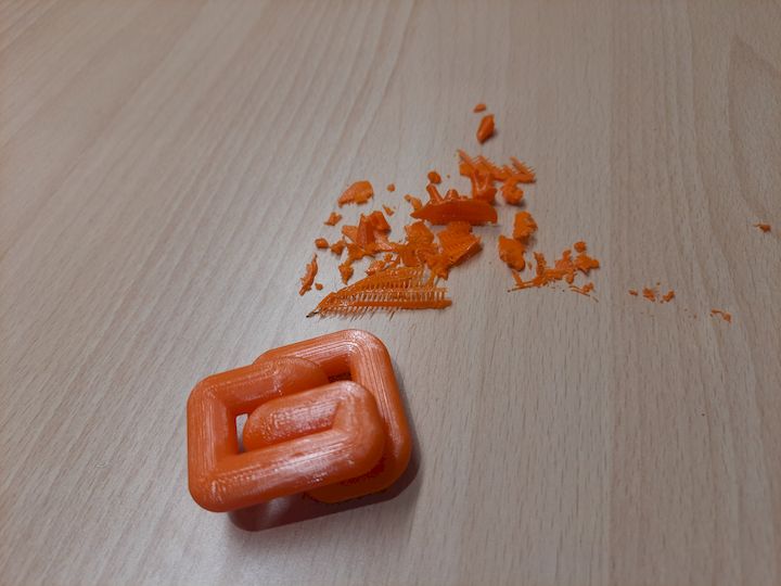
Figure 21: Final finished model.
3D Scanning using KIRI Engine
As in our lab we don't have any 3D Scanner, so we have to use the app called KIRI Engine
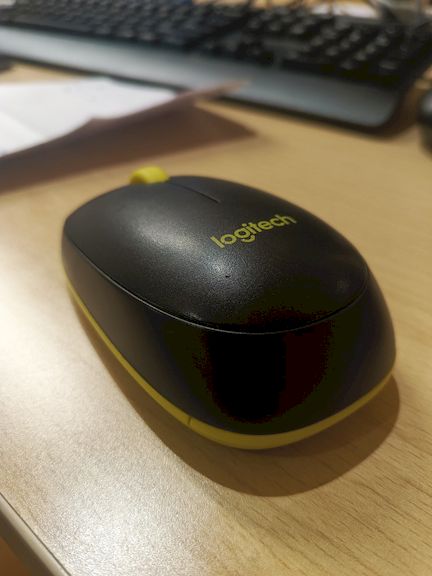
The object selected for scanning was my computer mouse
About KIRI Engine
Download KIRI Engine from Google Play Store
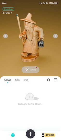
Figure 1: KIRI Engine application interface.
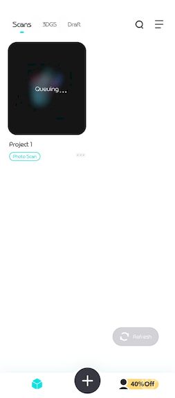
Figure 2: Creating a new scanning project.

Figure 3: Configuring scan settings.
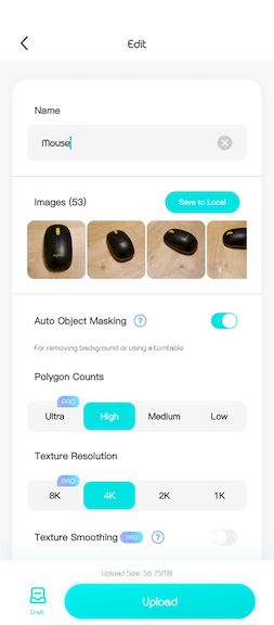
Figure 4: Preparing the image capture workflow.
For the initial 3D scanning experiment, I used the KIRI Engine mobile application. The application uses photogrammetry techniques to reconstruct a three-dimensional model from a collection of photographs. Images are captured from multiple viewpoints around the object and then processed to generate a textured 3D mesh.
To create the model, approximately 50 images were captured while moving around the object. These images were uploaded to KIRI Engine, where they were aligned and processed automatically. The software identified common feature points between images and reconstructed the object's geometry.
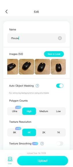
Figure 5: Uploading captured photographs.
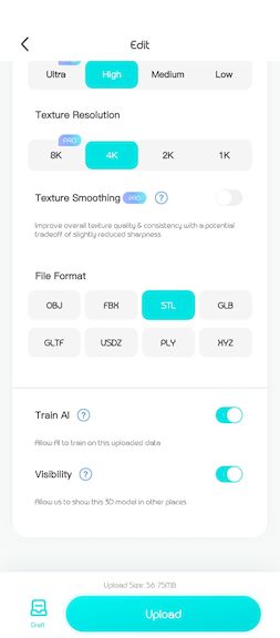
Figure 6: Processing images in KIRI Engine.
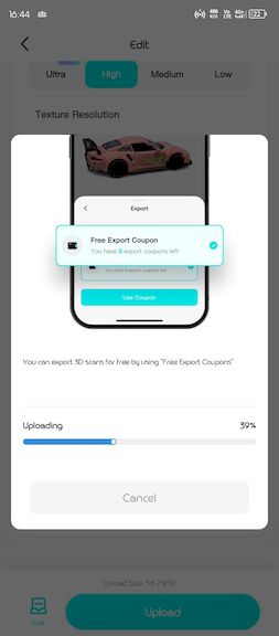
Figure 7: Generating the 3D mesh.
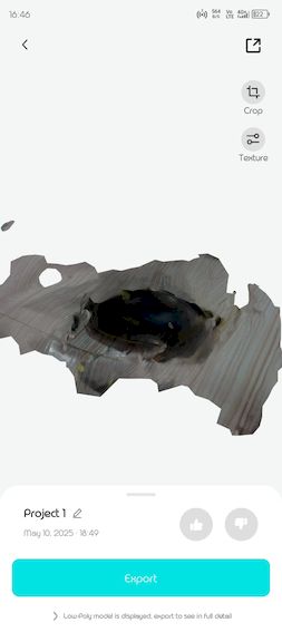
Figure 8: Initial reconstructed model.
Although the generated model successfully captured the overall shape of the object, some surface details and geometric features were not reconstructed accurately. This motivated me to explore an alternative workflow using Polycam to achieve a higher-quality scan result.
Re-Scanning using Polycam
Although KIRI Engine successfully generated a 3D model from the captured images, the reconstructed mesh contained several imperfections and missing surface details. To improve the quality of the reconstruction, I decided to perform a second scanning experiment using Polycam, a mobile-based photogrammetry application.
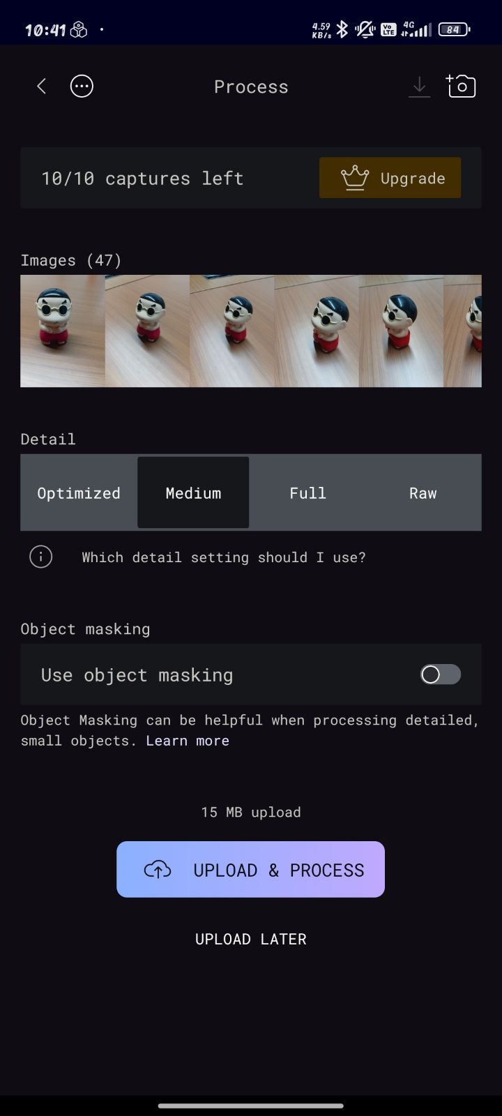
This second iteration allowed me to compare different photogrammetry workflows and evaluate how different reconstruction algorithms affect the final model quality. For this experiment, I selected a small Shinchan toy and captured a new set of photographs from multiple viewpoints.
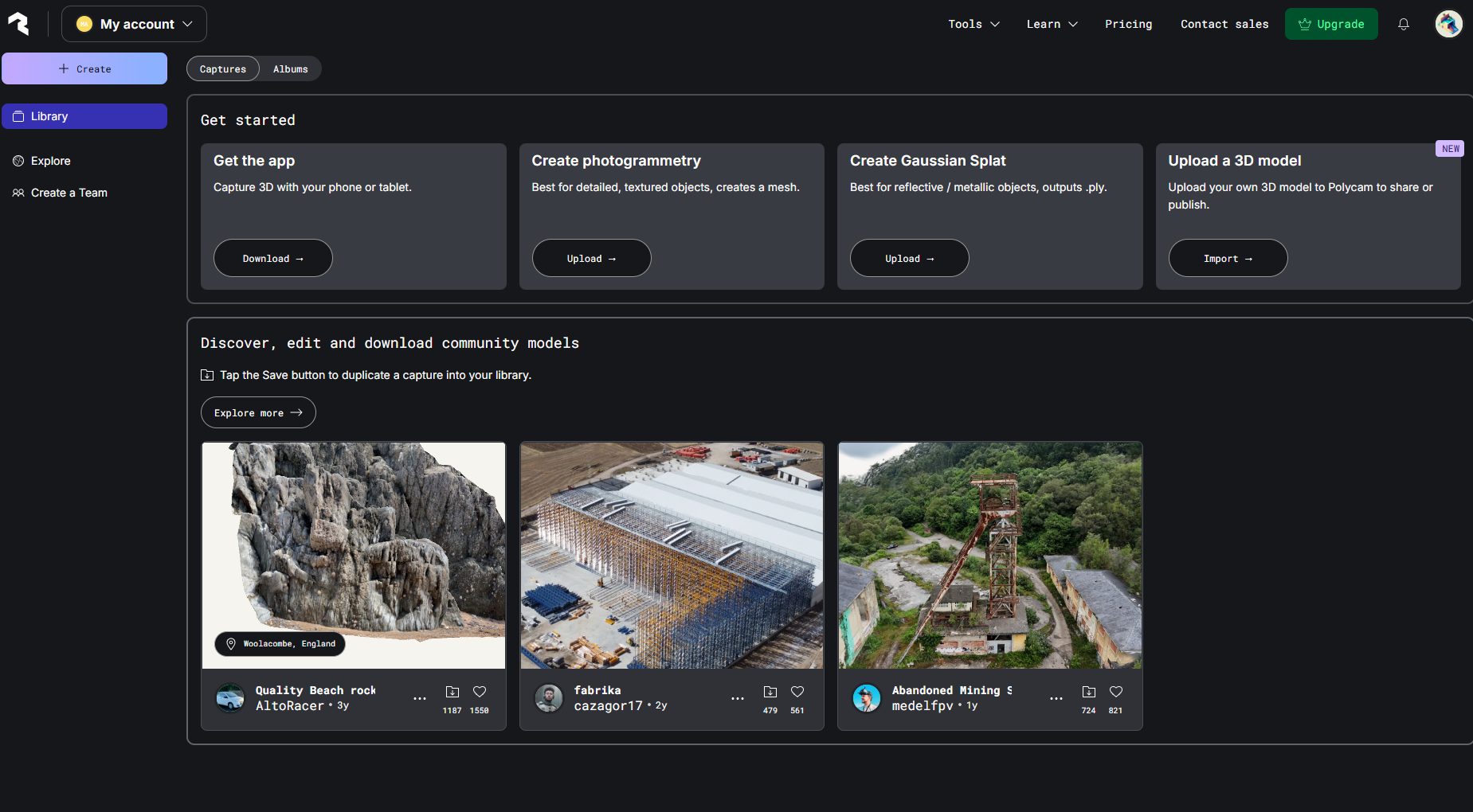
About Polycam
Polycam is a mobile 3D scanning and photogrammetry application available for Android and iOS devices. The software uses a collection of photographs captured from different viewpoints and reconstructs them into a textured 3D model. It supports exporting models in formats such as STL, OBJ, FBX, and GLTF, making it suitable for visualization, reverse engineering, and rapid prototyping workflows.
Scanning the Shinchan Toy
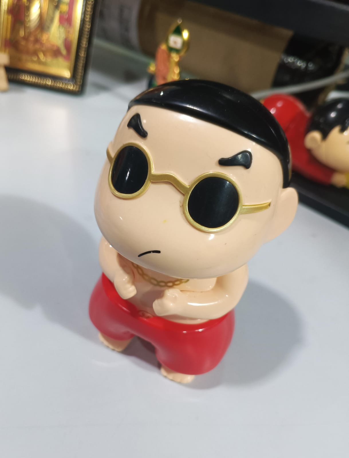
For this scanning experiment, I selected a small plastic Shinchan toy. The object contains curved surfaces, facial details, and geometric features that make it suitable for evaluating the performance of photogrammetry-based 3D reconstruction.
Using my smartphone, I captured multiple images while moving around the object from different angles. Photographs were taken from the front, rear, sides, and top views to ensure complete surface coverage. Maintaining sufficient overlap between images helped Polycam accurately identify common feature points and reconstruct the geometry.
Model Processing and Reconstruction
After completing the image acquisition process, Polycam processed the collected photographs and automatically generated a textured 3D model. The software analyzed common feature points between images and reconstructed the geometry using photogrammetry algorithms.
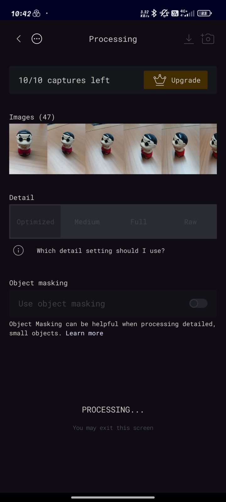
Figure 3: Textured 3D model generated by Polycam and previewed directly on the mobile device.
The generated model was then reviewed directly on the mobile device. This allowed me to inspect the reconstructed mesh, verify the captured details, and evaluate the overall quality of the scan before exporting the final model.
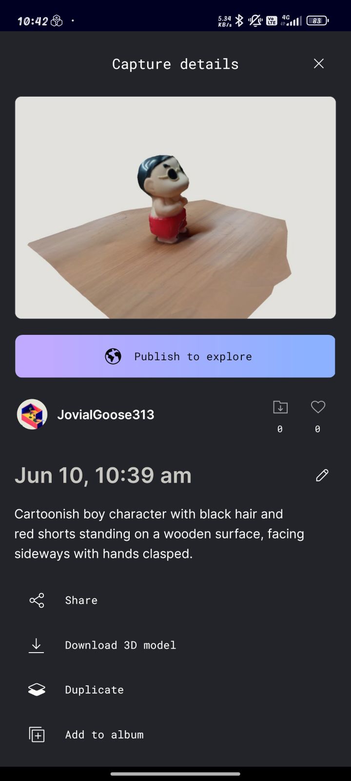
Figure 3: Textured 3D model generated by Polycam and previewed directly on the mobile device.
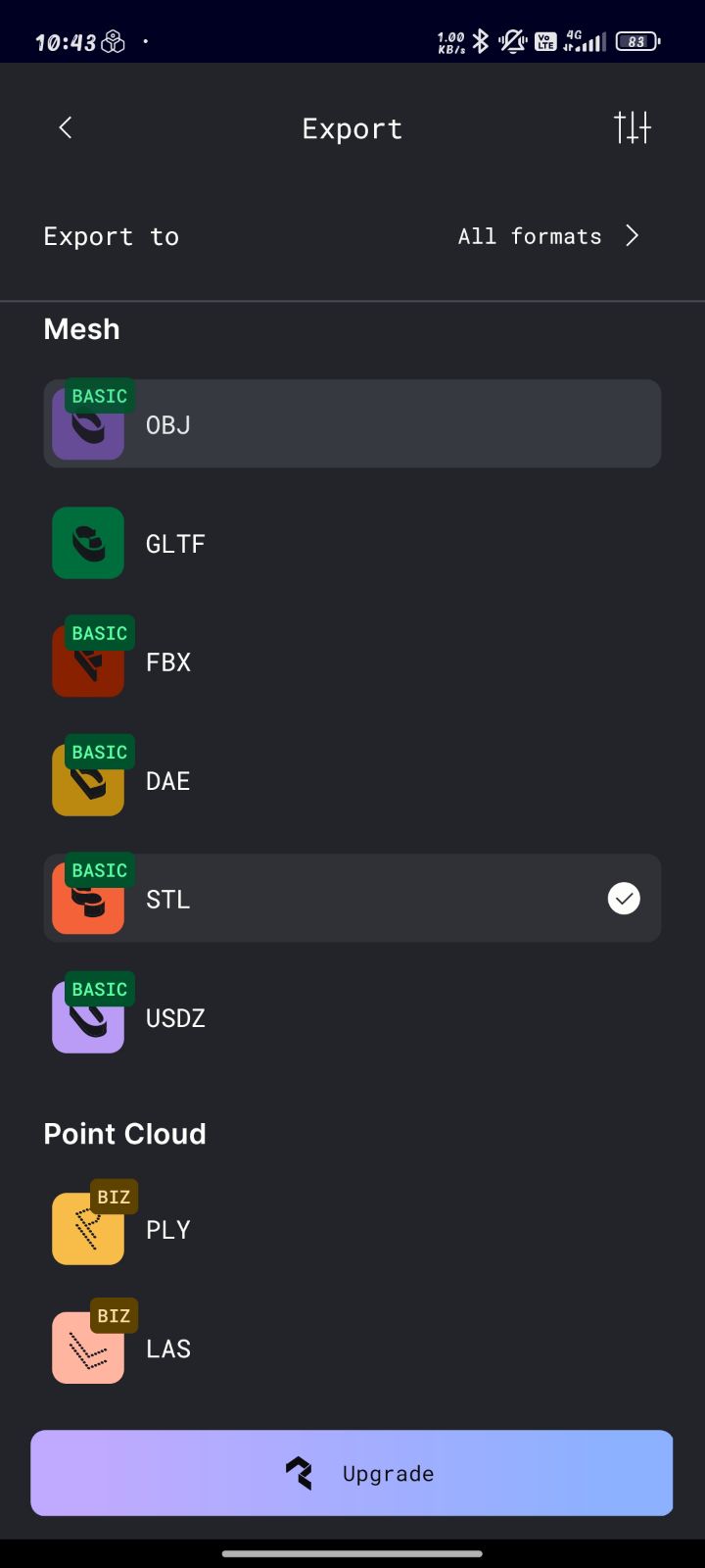
Exporting and Visualizing the Model
Once satisfied with the reconstruction quality, I exported the generated model in GLTF format. The exported file preserves both geometry and texture information, making it suitable for further visualization and sharing.
To inspect the model interactively, I uploaded the exported file to Sketchfab. The online viewer allowed me to rotate, zoom, and examine the reconstructed model from different angles. Compared to the initial KIRI Engine scan, the Polycam-generated model demonstrated better texture quality, improved surface reconstruction, and more accurate geometry.
Final 3D Scan Result
After performing the scan refinement process, KIRI Engine generated a significantly improved 3D model. The refinement stage reconstructed the geometry more accurately by analyzing additional image data and improving mesh generation. The final model preserved most of the object's surface details and overall shape, demonstrating the effectiveness of photogrammetry-based scanning using a smartphone.
The generated mesh was exported and uploaded to Polycam for visualization and sharing. The interactive viewer allows the model to be inspected from different angles and provides a better understanding of the reconstructed geometry.
Although the scan successfully captured the overall geometry, some minor surface imperfections and mesh artifacts were still visible. These limitations are common in photogrammetry workflows and can be reduced by increasing the number of input images, improving lighting conditions, and maintaining consistent camera positioning during image capture.
Compared to the initial KIRI Engine scan, the Polycam-generated model showed improved surface quality, better texture mapping, and more accurate geometric reconstruction. This exercise demonstrated how different photogrammetry tools can produce varying levels of detail depending on their reconstruction algorithms.
Learning Summary
- Learned the complete workflow of designing a custom 3D model using Fusion 360, including sketching, sweep operations, and appearance modifications.
- Understood the advantages of additive manufacturing and analyzed why complex internal geometries cannot be easily manufactured using conventional subtractive methods.
- Gained hands-on experience in preparing STL files for fabrication using Creality Slicer, including model scaling, orientation, support generation, and slicing configuration.
- Learned the importance of selecting appropriate printing parameters such as layer height, print speed, nozzle temperature, and bed temperature to achieve successful prints.
- Observed the complete 3D printing workflow from machine setup to final part fabrication and understood the operating characteristics of the FlashForge Creator 3 Pro printer.
- Evaluated the capabilities and limitations of photogrammetry-based 3D scanning using KIRI Engine and identified challenges related to image alignment and mesh quality.
- Explored Polycam as an alternative scanning solution and observed improvements in mesh reconstruction, texture mapping, and overall model quality.
- Successfully generated a 3D scan of a Shinchan toy by capturing images from multiple viewpoints using a smartphone camera.
- Learned how to process, export, and visualize scanned models using GLTF format and online 3D model viewing platforms.
- Developed a better understanding of the complete digital fabrication workflow, from CAD design and additive manufacturing to 3D scanning and digital model reconstruction.
Hero Shot
Finally Leaving my files here
I can't able to export those STL files of Mouse and Shinchan Toy due to subscription restriction. Sorry :-(
Contents
- Objectives of the Week
- Group Assignment Contribution
- 3D Printer Specifications
- Designing the 3D Model
- Why Not Subtractive?
- Creality Slicer Workflow
- Print Configuration
- Machine Setup
- Printing Process
- Final Printed Model
- 3D Scanning using KIRI Engine
- Polycam Second Iteration
- Scanning the Shinchan Toy
- Model Processing and Export
- Learning Summary
- Hero Shot
- Design Files