- Week 1 : Project Management
- Week 2 : Computer-aided
- Week 3 : Computer Controlled Cutting
- Week 4 : Embedded Programming
- Week 5 :3D Scanning and Printing
- Week 6 : Electronic Design
- Week 7 : Computer Controlled Machining
- Week 8 : Electronics Production
- Week 9 : Input Devices
- Week 10 : Output Devices
- Week 11 : Networking and Communication
- Week 12 : Mechanical Design and Machine Design
- Week 14 : Molding and Casting
- Week 15 : Interface and Application Programming
- Week 16 : System Integeration
- Week 17 : Wildcard Week
- Week 18 : Applications and Implications, Project Development
- Week 19 : Invention, Intellectual property and Income
- Week 20 : FInal Project Requirements
Week 17: System Integeration
Objectives of the Week
For More about Final Project
System Integration
So, when we talk about system integration, we're basically referring to the process of combining all the different parts of a system—things like sensors, controllers, actuators, displays—into one complete setup that works together smoothly. It’s not just about connecting wires or writing code for each part, but making sure they all communicate properly, both in terms of hardware and software.
In robotics or product development, this means aligning everything—electronics, the mechanical build, power supply, and programming logic—so the entire system behaves the way we want it to. If it's done right, system integration helps reduce complexity, improves how the robot performs, and makes it much easier to control and troubleshoot. The goal is to make sure the whole system meets functional needs, runs safely, and is easy to use.
About My Final Project - Line Bot
Overview
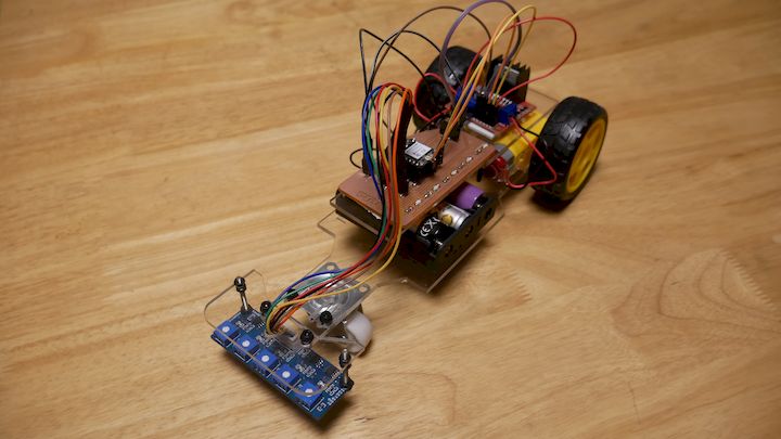
For my final project at Fab Academy, I built a robot called the Line Bot, which is an autonomous line-following mobile robot. The idea is simple but powerful—the robot can detect and follow a path marked on the ground using infrared sensors.
Main Components
- XIAO ESP32-C3 – Main microcontroller handling logic and control
- Custom Motor + Sensor Interface PCB – Designed and fabricated for organized integration
- BO Motors with Plastic Wheels – Used for smooth movement
- L298N Motor Driver – Dual H-Bridge module to control motor direction and speed
- 5-Line IR Sensor Array – Detects the line on the floor
- OLED Display – Shows live feedback like sensor data or direction
- Acrylic Chassis – Laser-cut sheet that holds the components
- JST Connectors – For neat and reliable wiring
- Li-ion Battery – To power the complete system
- Line Marker Tape – Used to lay the black path on white surface
Working Principle
The 5-line IR sensor array reads the contrast between the black line and white background. Based on this input, the ESP32-C3 calculates motor speed adjustments using PWM signals. The L298N driver then controls the left and right BO motors accordingly to follow the line precisely.
The OLED display provides real-time information, helping during testing and debugging. All wiring is routed through JST connectors to maintain reliability and reduce loose connections.
System Testing
The system was tested under various lighting and surface conditions to verify sensor accuracy and motor control. Integration was carefully checked to ensure all modules—from sensors to motors—communicate and perform in sync. The final robot delivers stable, smooth, and accurate line-following performance.
Bill of Materials (BoM)
The following table summarizes the major components used in the development of the Line Following Robot. The costs are approximate and may vary depending on supplier and procurement quantity.
| S.No | Component | Description | Quantity | Unit Cost (₹) | Total Cost (₹) |
|---|---|---|---|---|---|
| 1 | XIAO ESP32-C3 | Main microcontroller for robot control and processing | 1 | 750 | 750 |
| 2 | Custom Fabricated PCB | Main control and sensor interface boards | 2 | 150 | 300 |
| 3 | BO Gear Motors | DC geared motors for locomotion | 2 | 180 | 360 |
| 4 | Robot Wheels | Compatible wheels for BO motors | 2 | 60 | 120 |
| 5 | L298N Motor Driver | Dual H-Bridge motor driver module | 1 | 180 | 180 |
| 6 | 5-Channel IR Sensor Array | Line tracking sensor module | 1 | 250 | 250 |
| 8 | JST Connectors & Wiring | Interconnection cables and connectors | 1 Set | 150 | 150 |
| 9 | Header Pins | Male and female pin headers | 1 Set | 50 | 50 |
| 10 | Acrylic Chassis | Laser-cut structural base frame | 1 | 150 | 150 |
| 11 | Rechargeable Battery Pack | Power source for the robot | 1 | 400 | 400 |
| 12 | Fasteners | Screws, nuts, spacers, and mounting hardware | 1 Set | 100 | 100 |
Total Estimated Cost: ₹2,810
The overall cost was kept low by utilizing in-house fabricated PCBs, laser-cut acrylic components, and readily available educational robotics hardware. The design emphasizes affordability, ease of assembly, and suitability for learning embedded systems, PCB design, and autonomous mobile robotics.
Line Follower Bot Gantt Chart
Subsystem 1: Mechanical Design and Fabrication
| Task | Week 1 | Week 2 | Week 3 | Week 4 |
|---|---|---|---|---|
| Rough Sketch | ||||
| CAD Modelling | ||||
| Component Selection | ||||
| 3D Printing | ||||
| Assembly & Fitting |
Subsystem 2: On-Bot PCB Design
| Task | Week 1 | Week 2 | Week 3 | Week 4 |
|---|---|---|---|---|
| Schematic Design | ||||
| Power Calculation | ||||
| PCB Layout | ||||
| Fabrication & Testing |
Subsystem 3: Sensor + Line Following Logic
| Task | Week 1 | Week 2 | Week 3 | Week 4 |
|---|---|---|---|---|
| IR Sensor Calibration | ||||
| Threshold Tuning | ||||
| Tracking Algorithm |
Subsystem 4: Bot Control Software
| Task | Week 1 | Week 2 | Week 3 | Week 4 |
|---|---|---|---|---|
| PWM + PID Setup | ||||
| Motor Control Logic | ||||
| Serial Debug + Logs |
Subsystem 5: Testing and Final Tuning
| Task | Week 1 | Week 2 | Week 3 | Week 4 |
|---|---|---|---|---|
| Integration Test | ||||
| Performance Test | ||||
| Final Field Run |
4. Component Overview
- Microcontroller: XIAO ESP32-C3 - Compact, low-power board with built-in Wi-Fi and Bluetooth. Responsible for all sensor processing and motor control.
- Motor Drivers: L298N Dual H-Bridge Motor Driver - Controls two BO motors independently through PWM.
- Sensors: 5-Channel Infrared Sensor Array - Used to detect the contrast between black line and white background. Analog or digital values processed by ESP32.
- Display: 0.96" OLED I2C Display - Displays real-time sensor readings, motor status, and debug messages.
- Power System: Li-ion battery (3.7V) with boost converter to 5V/7.4V output.
- Mechanical: Acrylic Base (laser-cut), BO motors with wheels, mounting hardware, and wiring using JST connectors.
5. Electronics Architecture
The electronics design was tailored for simplicity and efficiency. The ESP32-C3 interfaces with:
- IR sensor via analog/digital input pins.
- L298N motor driver via PWM-enabled GPIOs.
- OLED via I2C communication (SCL, SDA).
- Power supplied from a Li-ion battery regulated via onboard voltage converters.

The system wiring was planned carefully to ensure minimal noise, secure connections, and clear power/data paths. The use of JST connectors simplified replacements and debugging.
6. Mechanical Structure
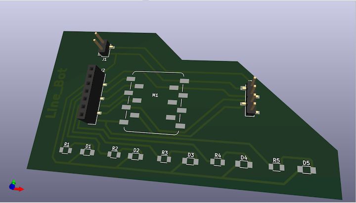
The body of the robot was designed in CAD and laser cut using 3mm acrylic sheet. The design considerations included:
- Adequate spacing between wheels and sensors.
- Firm placement of motor driver and MCU.
- Slots for wiring and connectors.
- Mounting holes for sensors to face the ground at a proper angle.
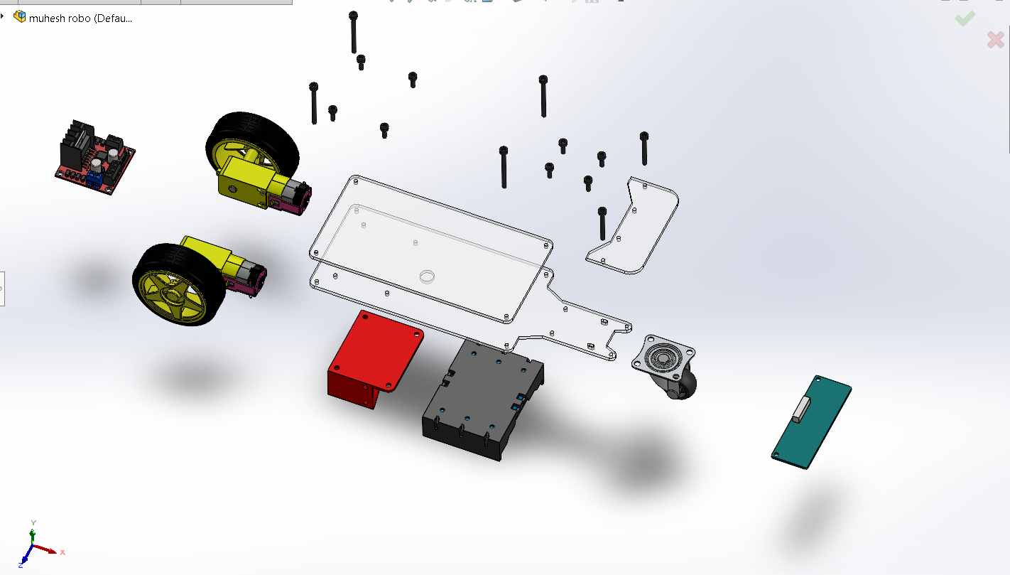
Figure: 3D CAD model of the Line Bot showing component placement and overall mechanical structure.
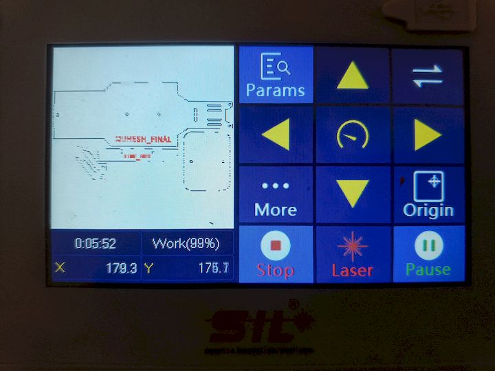
Laser Cutting Process
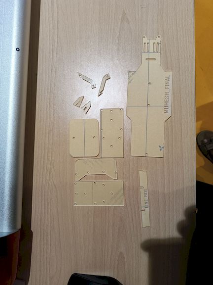
The BO motors were mounted using acrylic brackets, and the IR sensor array was placed at the front underside. The final structure e nsured good balance, durability, and access for debugging.
PCB Assembly
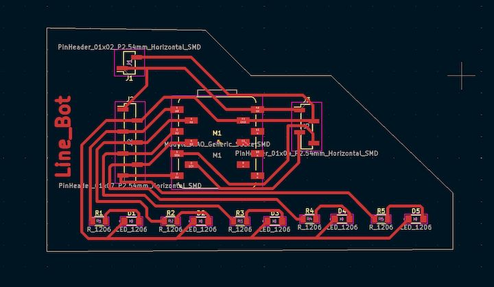
The BO motors were mounted using acrylic brackets, and the IR sensor array was placed at the front underside. The final structure e nsured good balance, durability, and access for debugging.
Integerated Part initial PoC
Cable Management and Packaging Improvements
One of the key objectives of the System Integration week was to transform the prototype into a more organized and finished product. During the initial proof-of-concept stage, the wiring was functional but not properly managed, which made maintenance and troubleshooting difficult.
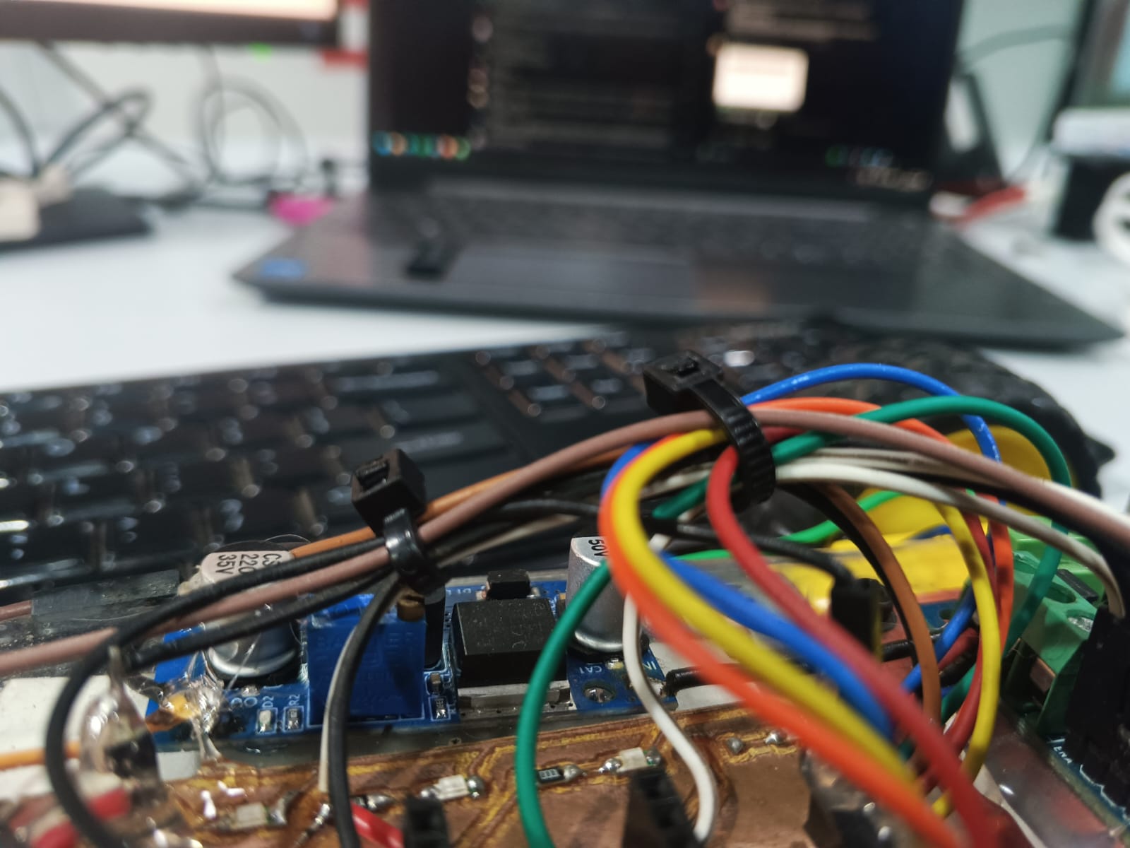
Figure: Improved cable management using zip ties to organize and secure wiring connections.
To improve the overall packaging quality, the cables were grouped according to their function and secured using zip ties. Power wires, signal wires, and communication cables were routed together to reduce clutter and prevent accidental disconnections during robot operation.
The improved cable management provides several benefits:
- Reduced wire entanglement and mechanical stress.
- Improved reliability of electrical connections.
- Easier debugging and maintenance.
- Cleaner appearance and better product presentation.
- Improved safety by preventing loose wires from interfering with moving parts.
Reflection
Through this activity, I learned that system integration is not only about making the electronics and software function correctly, but also about improving the physical organization of the system. Proper cable management enhances reliability, simplifies maintenance, and contributes significantly to the overall quality and professionalism of the final product.
Project Files and Resources
To ensure reproducibility and open-source accessibility, all design files, source code, and project documentation related to the Line Bot project are provided below. These files allow anyone to understand, modify, fabricate, and further develop the system.
Source Code
Electronics Design Files
Mechanical Design Files
All files have been developed as part of the Fab Academy final project and are provided to support documentation, replication, future development, and educational use.