- Week 1 : Project Management
- Week 2 : Computer-aided
- Week 3 : Computer Controlled Cutting
- Week 4 : Embedded Programming
- Week 5 :3D Scanning and Printing
- Week 6 : Electronic Design
- Week 7 : Computer Controlled Machining
- Week 8 : Electronics Production
- Week 9 : Input Devices
- Week 10 : Output Devices
- Week 11 : Networking and Communication
- Week 12 : Mechanical Design and Machine Design
- Week 14 : Molding and Casting
- Week 15 : Interface and Application Programming
- Week 16 : System Integeration
- Week 17 : Wildcard Week
- Week 18 : Applications and Implications, Project Development
- Week 19 : Invention, Intellectual property and Income
- Week 20 : FInal Project Requirements
Week 14 : Molding and Casting
Objectives of the Week
- Linked to the group assignment page and reflected on your individual page what you have learned
- Reviewed the safety data sheets for each of your molding and casting materials, then made and compared test casts with each of them
- Documented how you designed and created your 3D mold, including machine settings
- Ensured your mold has smooth surface finish, that does not show the production process
- Shown how you safely made your mold and cast the parts
- Described problems and how you fixed them
- Included your design files and 'hero shot' of the mold and the final object
Group Assignment Contribution
For More about Group Assignment
Reviewing the data sheets
1. Silicone Rubber (e.g., OOMOO, Dragon Skin)
Silicone rubbers are widely used for flexible molds. They are generally safe but can cause mild skin and eye irritation during mixing. Most formulations are platinum-cured or tin-cured and are two-part systems.
Hazards
Low toxicity, but some components may cause irritation on contact. Vapors are usually minimal but should still be avoided in confined areas.
Handling
Wear nitrile gloves to prevent direct contact. Safety glasses should be used when mixing or pouring. Avoid breathing vapors and always work in a ventilated space.
Storage
Keep containers tightly closed when not in use. Store at room temperature, away from direct sunlight and moisture.
First Aid
In case of skin contact, wash thoroughly with soap and water. If it contacts the eyes, flush immediately with water for several minutes. Seek medical help if irritation persists.
2. Polyurethane Resin (e.g., Smooth-Cast Series)
Polyurethane resins are popular for hard casting. They typically come in Part A and Part B components that chemically react to form rigid plastics. Isocyanates in Part A are a significant health concern.
Hazards
Can cause serious skin and eye irritation. Vapors may irritate the respiratory system. Sensitization is possible with repeated exposure.
Handling
Use nitrile gloves, chemical splash goggles, and work in a fume hood or well-ventilated area. Avoid any contact with skin and do not inhale vapors.
Storage
Store in tightly sealed containers. Moisture-sensitive—exposure to humidity can ruin the material or cause dangerous reactions.
First Aid
Seek immediate medical attention if inhaled. If skin contact occurs, wash immediately with soap and warm water. Rinse eyes thoroughly if exposed.
3. Epoxy Resin (e.g., West System, ArtResin)
Epoxy resins are two-part thermosetting polymers used for clear casting and coatings. Though common, they require careful handling to avoid long-term sensitization and allergic reactions.
Hazards
Skin sensitizer and moderate irritant. Inhalation of vapors can cause headaches or nausea. Repeated exposure may lead to allergies or dermatitis.
Handling
Always wear gloves (preferably nitrile), safety goggles, and ensure you have proper airflow. Use a respirator if working with large volumes or poor ventilation.
Storage
Store both parts in original containers, tightly sealed, in a cool, dry location. Avoid contamination between Part A and Part B.
First Aid
Wash exposed skin with soap and water immediately. If epoxy contacts eyes, rinse for 15 minutes with clean water. Seek medical attention if irritation or allergic symptoms occur.
4. Alginate (e.g., Dental Grade or Life Casting Alginate)
Alginate is a natural material derived from seaweed, often used for body part molding due to its skin safety. It is mixed with water and cures quickly to form flexible molds.
Hazards
Generally non-toxic and safe for skin. Inhalation of fine powder may cause irritation to the respiratory system. Not recommended for use around open wounds.
Handling
Wear a dust mask while mixing dry alginate to avoid inhaling particles. Gloves are optional unless sensitive skin is involved. Avoid spilling powder on wet surfaces, as it can become slippery.
Storage
Keep dry and sealed in an airtight container. Exposure to moisture can ruin the powder or shorten its shelf life.
First Aid
If inhaled, move to fresh air and rinse mouth. If in eyes, flush gently with water. If irritation occurs on skin, rinse with warm water and stop use.
5. General Safety Guidelines
- Always read the full Safety Data Sheet (SDS) before use.
- Wear Personal Protective Equipment (PPE): gloves, goggles, mask/respirator as needed.
- Ensure good ventilation or use fume extraction systems.
- Label materials and store safely away from food, flames, or sunlight.
- Dispose of uncured materials as hazardous waste per local regulations.
Individual Assignment
Now Let's jump into the Individual Assignment
Molding and Casting
Molding and casting are powerful manufacturing techniques used to duplicate objects by first creating a mold of the desired shape and then filling it with a casting material. This process is essential in both prototyping and production, offering the ability to replicate intricate geometries with high precision, repeatability, and efficiency across a variety of materials.
Types of Molding and Casting
Various types of molding and casting methods exist, each tailored to specific materials, applications, and production volumes. Below is a breakdown of some of the most widely adopted techniques, categorized into molding and casting processes.
Types of Molding
Compression Molding
This method involves placing a preheated material—typically a thermoset plastic—into a heated mold cavity. The mold is then closed and pressure is applied to shape the material. It is frequently used for manufacturing automotive parts, electrical insulators, and durable kitchenware.
- Advantages: Minimal material waste, ideal for large-sized components
- Disadvantages: Slower cycle time, not suitable for intricate details
Injection Molding
Molten plastic is injected under high pressure into a mold cavity to form complex shapes quickly and accurately. It is the most common method used for producing plastic products like packaging, toys, and electronic housings.
- Advantages: High-speed production, excellent accuracy, scalable for mass manufacturing
- Disadvantages: High cost of tooling and setup
Blow Molding
This process is primarily used to create hollow plastic parts such as bottles. A heated plastic preform is inflated inside a mold until it conforms to the cavity’s shape.
- Advantages: Fast production, perfect for hollow shapes
- Disadvantages: Only suitable for hollow items, limited shape complexity
Rotational Molding
Plastic powder is placed inside a mold that is rotated on multiple axes while being heated. The powder melts and evenly coats the inner surfaces of the mold, forming a hollow object.
- Advantages: Even wall thickness, cost-effective molds
- Disadvantages: Long cycle time, not ideal for small, detailed parts
Types of Casting
Sand Casting
This traditional process involves pouring molten metal into a mold made of compacted sand. After the metal solidifies, the sand mold is broken to extract the final product.
- Advantages: Inexpensive, suitable for producing large or bulky components
- Disadvantages: Coarse surface texture, less dimensional precision
Investment Casting (Lost Wax)
A wax model is created and coated with a ceramic shell. Once the shell hardens, the wax is melted out, and molten metal is poured in. Ideal for fine, detailed metal parts.
- Advantages: Exceptional accuracy and surface finish
- Disadvantages: Expensive, labor-intensive, slower process
Die Casting
This method uses high-pressure injection of molten metal into steel molds. Commonly used for high-volume production of parts made from aluminum, zinc, and magnesium.
- Advantages: High dimensional accuracy, very fast cycle times
- Disadvantages: High tooling cost, suitable only for non-ferrous metals
Plaster Casting
Similar to sand casting but utilizes a plaster-based mold for better surface finish and detail. Best for non-ferrous metals and low-volume production.
- Advantages: Fine detail reproduction, smooth surface finish
- Disadvantages: Fragile molds, only for low-melting-point metals
Version 1 - FDM Printed Mold
Mold Design
In the initial stage of mold design, we begin by constructing a basic geometric form in SolidWorks. The foundation starts with a 2D sketch of a circle with a diameter of 50 mm. This dimension is used as the base size for a series of concentric features that gradually build up the complexity of the mold. This approach allows for precision control over thickness and depth, which is critical when creating molds for casting.
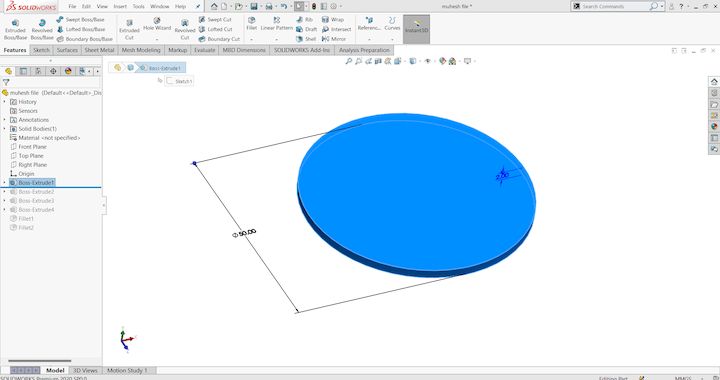
Stage 1: We create a base circular sketch of 50 mm diameter. This sketch will serve as the primary profile on which further design layers will be built. It represents the outermost edge of the mold geometry.
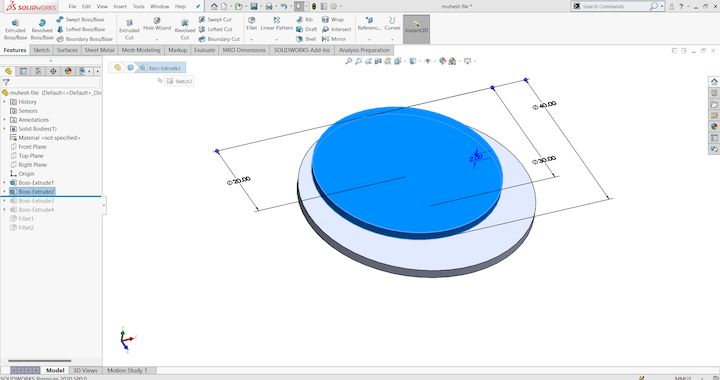
Stage 2: An inner concentric circle is added inside the base sketch to create a stepped feature. This step marks the beginning of layering and adds a second level of surface that will influence the casting shape when poured.
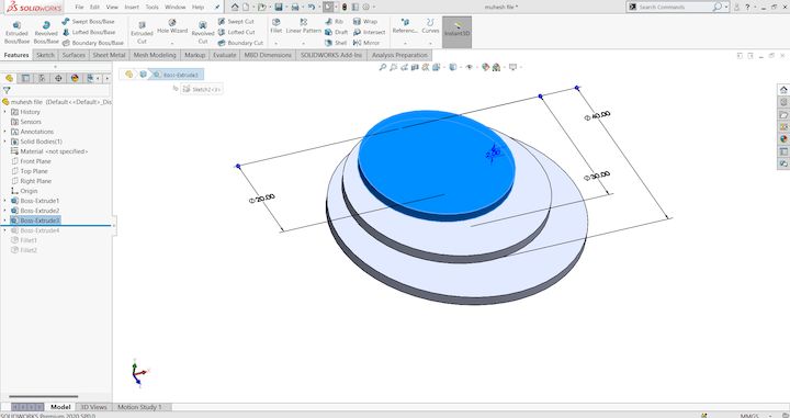
Stage 3: Additional concentric sketches are created inside the second layer, continuing the stepped pattern. These intermediate circular boundaries allow us to design distinct zones that will later be extruded to different heights, giving depth to the mold's internal cavities.
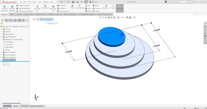
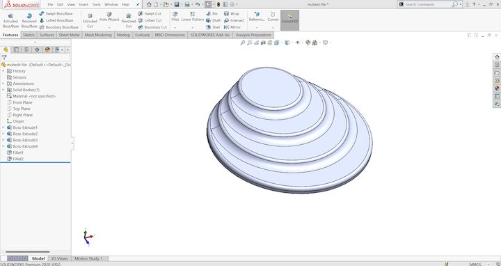
Stage 4: Each of the concentric profiles is extruded to form a stepped 3D structure. The heights are carefully assigned to define mold contours and capture fine details that would appear in the final casted product. This extruded solid is now fully ready for the transition into CAM.
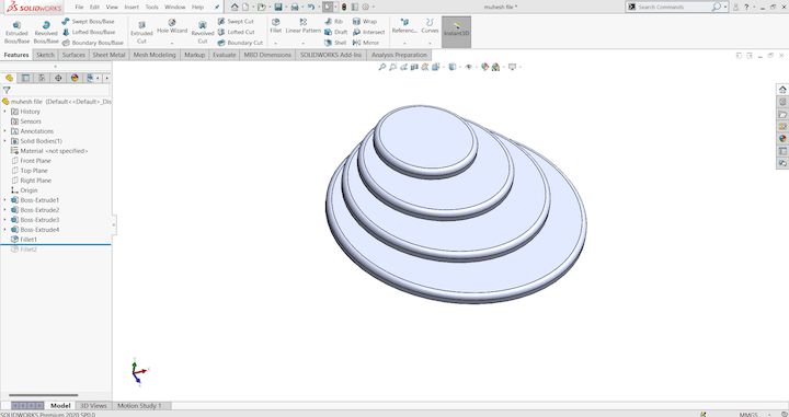
Stage 5: The model is reviewed in isometric view to verify accuracy and dimensional integrity. This ensures the design meets both aesthetic and functional requirements before proceeding further. It also allows for error detection before exporting the file for toolpath generation.
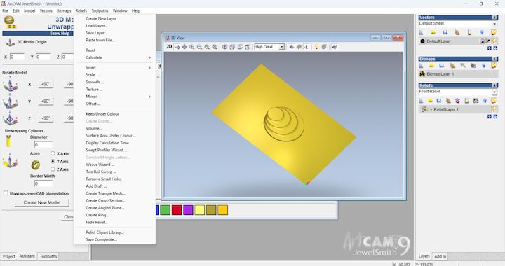
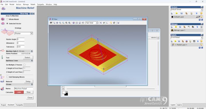
CAM Toolpath Generation in ArtCAM
Once the 3D model is finalized in SolidWorks, the next step is to generate CNC-compatible toolpaths in ArtCAM. This software enables us to create a precise machining strategy, converting our 3D geometry into instructions the milling machine can follow. ArtCAM is especially useful in mold-making due to its visual interface and robust toolpath simulation capabilities. The following stages demonstrate how the model is processed for machining.
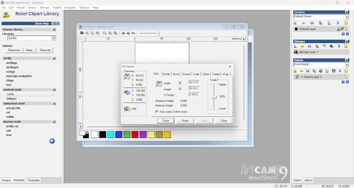
Stage 1: The SolidWorks model is imported into ArtCAM. We begin by defining the size of the material block that matches or exceeds the dimensions of the 3D model. Proper placement of the model within this material block ensures all features can be milled without overcuts.
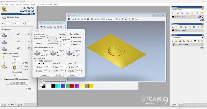
Stage 2: We establish the Z-zero position and machining boundaries. This setup is essential to instruct the CNC machine where to begin cutting and how deep to go. The alignment of the workpiece on the bed and the tooling origin are defined here.
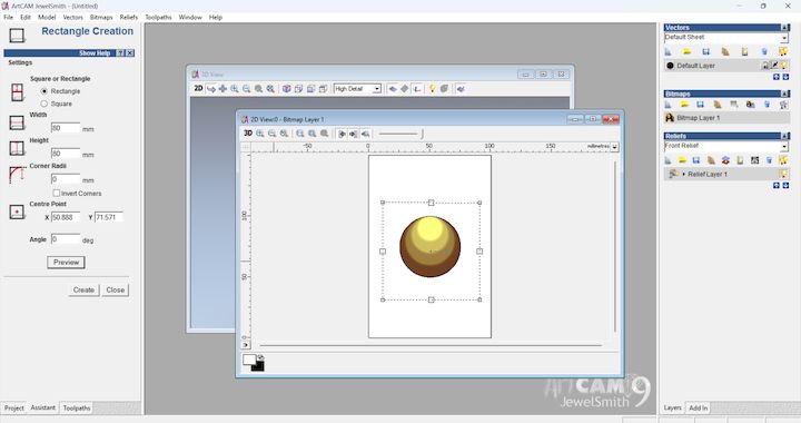
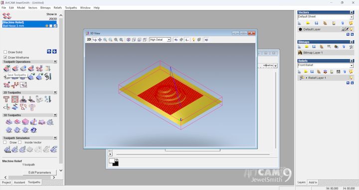
Stage 3: A roughing toolpath is generated using a larger end mill. This step removes the bulk of the material quickly, following a safe margin from the actual design to avoid damaging detailed areas. Parameters like step-down depth and tool overlap are carefully adjusted.

Stage 4: Once roughing is done, a finishing toolpath is created with a smaller tool, such as a ball-end mill. This toolpath follows the precise contour of the mold, ensuring that all intricate details and curved surfaces are milled with high accuracy.
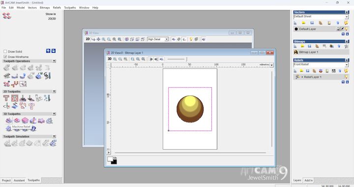
Stage 5: A simulation is run to visualize how the tool interacts with the material. This simulation is essential to preview the final finish and to spot any tool collisions or incomplete areas before committing to real machining. Adjustments are made based on this output.
Stage 6: A close-up view of the finishing simulation shows the precise ridges and depth transitions of the design. This stage validates the quality of surface finish and confirms that the machining strategy captures the fidelity of the original SolidWorks model.
Stage 7: Depth visualization is applied to the toolpaths, showcasing Z-axis movement. This allows better understanding of the cutting profile and ensures that each layer is milled progressively without overloading the tool.
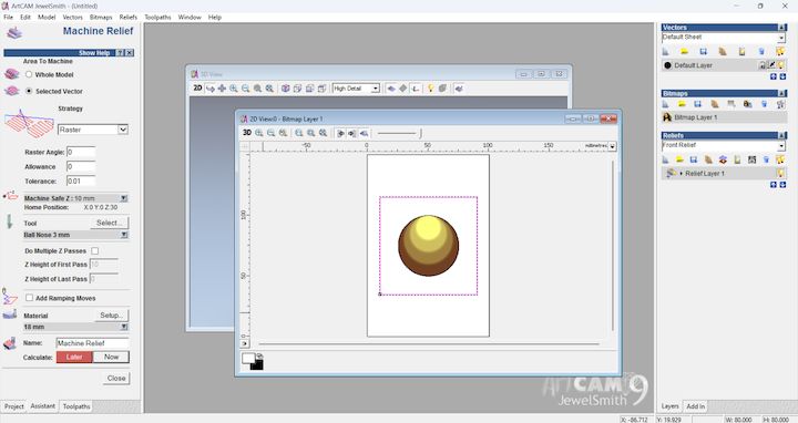
Stage 8: Final validation of toolpaths and selection of post-processor format compatible with your CNC machine (e.g., GRBL, Mach3). ArtCAM then generates the G-code, which is the instruction set that guides the CNC router to execute the mold carving process.
Stage 9: Toolpaths are exported, and the setup is now ready for physical machining. The result will be a precision-cut mold cavity, made from the CAD model and refined through CAM simulations, ready for casting processes like silicone, resin, or wax pouring.
Introduction
In the initial stages of mold fabrication, we opted to use CNC milling to create a precise mold. However, the process encountered a critical setback. During the milling operation, the tool bit fractured due to an excessive depth of cut. This tool failure not only delayed the timeline but also posed a risk of material wastage. To address this issue efficiently and continue progress, we decided to pivot from CNC milling to 3D printing for mold fabrication.
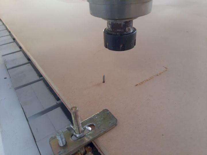
Switch to 3D Printing Method
The decision to switch to 3D printing was strategic. 3D printing provided a quicker alternative with a high degree of detail and accuracy. It also offered the benefit of avoiding further material wastage or equipment damage. Using PLA as the material of choice, we initiated the 3D printing process by first preparing the model.
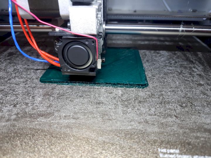
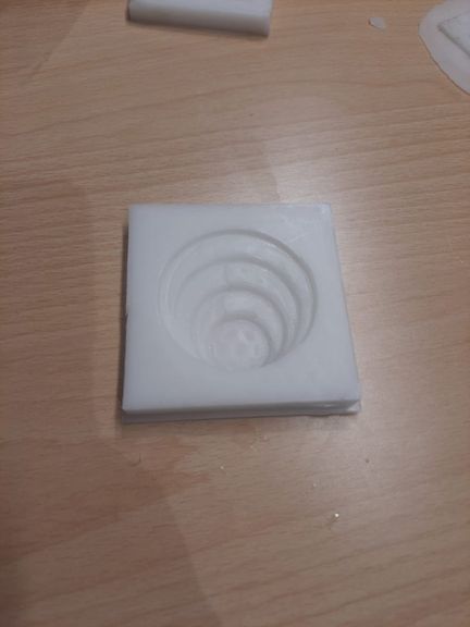
The STL file was exported from SolidWorks and imported into slicing software. Print settings were carefully optimized to ensure a high-quality finish. One critical setting was the layer height, which was adjusted to 0.1 mm. This fine resolution setting played a crucial role in capturing intricate surface details of the mold, ensuring that the final printed object met precision and quality expectations.
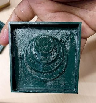
The 3D printing process concluded successfully, resulting in a mold that faithfully reproduced the design intent. The printed mold had a smooth surface and detailed contours, thanks to the optimized settings, particularly the layer height.
Preparation for Silicone Mold Casting
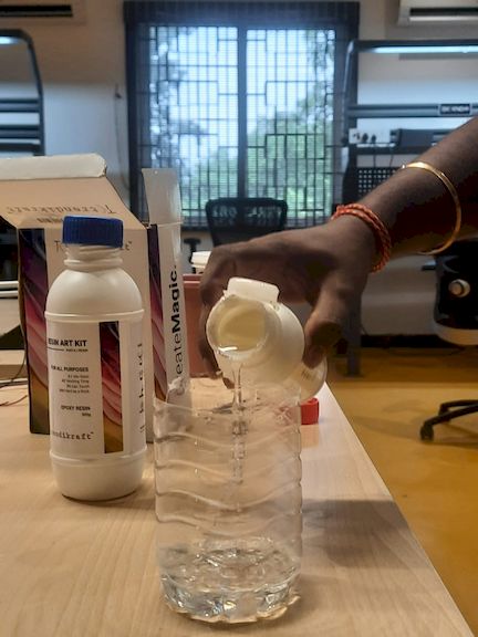
Before proceeding to cast silicone into the 3D printed mold, it was essential to estimate the required volume of silicone. Accurate measurement was vital to avoid material shortage or wastage.
To calculate the needed silicone volume, we filled the 3D printed cavity with water. This method allowed us to determine the mold's internal volume precisely. The water was then poured into a 250 ml measuring beaker to record the total volume.
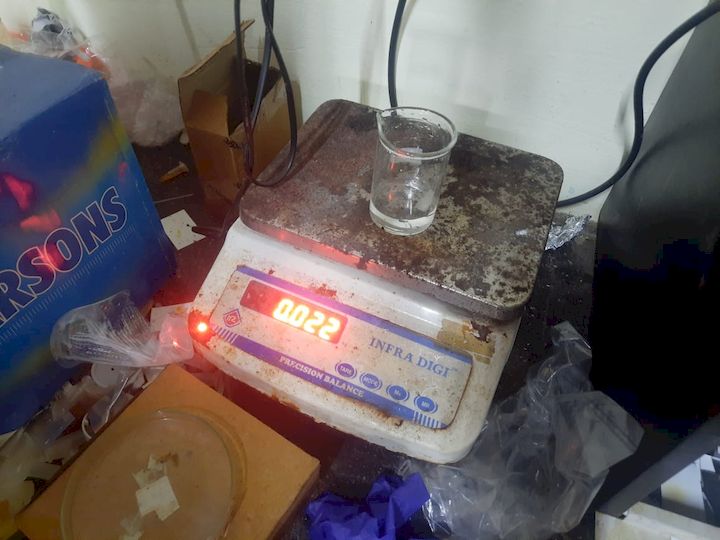
Prior to pouring the water, we tared the beaker by recording its empty weight. This ensured that the final volume measurement excluded the beaker's weight, giving a true representation of the mold's internal capacity.
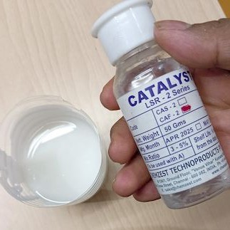
Using the recorded volume, we turned to an online silicone mold calculator to determine the appropriate quantities of silicone base and catalyst. The calculator helped derive the exact ratio and amounts for each component, ensuring the final mix would cure properly and produce a durable, bubble-free mold.
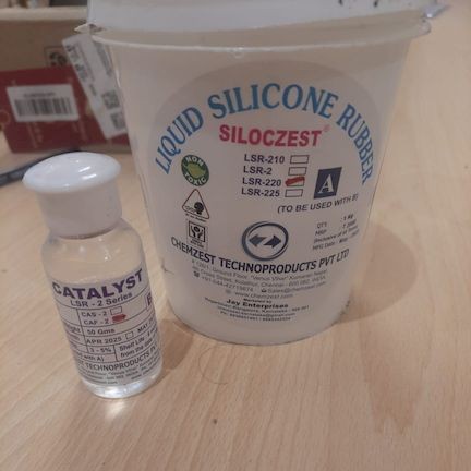
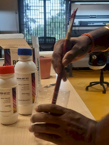
Silicone Mixing Process
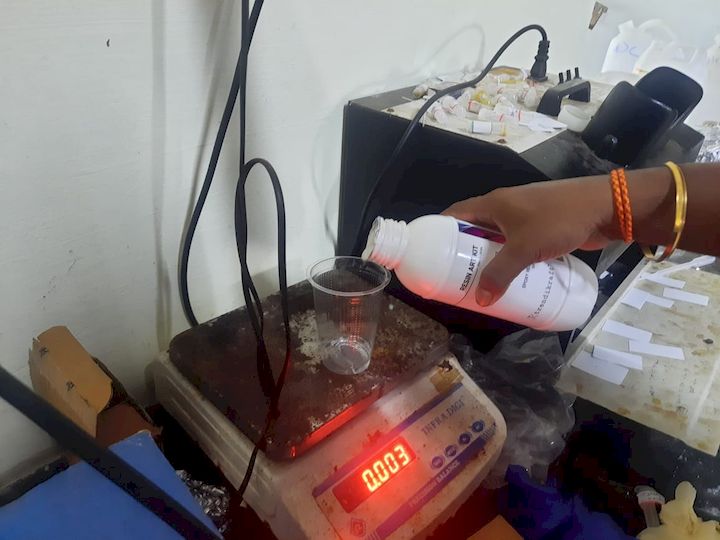
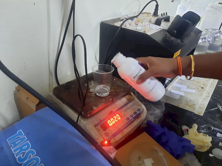
Equipped with protective gloves for safety, we began the silicone mixing process. The silicone base was poured into a clean plastic beaker. Once the base was added, we tared the beaker again to zero out the scale. This allowed us to measure the catalyst separately and accurately.
According to the calculated ratio, we added 2 grams of catalyst to the silicone base. Precision in this step is critical, as incorrect measurements can lead to curing failures or weak molds. The mixture was then stirred thoroughly to ensure an even distribution of catalyst throughout the base. Mixing was done slowly to minimize air bubble formation.
After the mixture was homogenous, it was left to settle briefly. This allowed any air bubbles that may have formed during stirring to rise to the surface and escape, reducing defects in the final mold.
Pouring the Silicone into the Mold
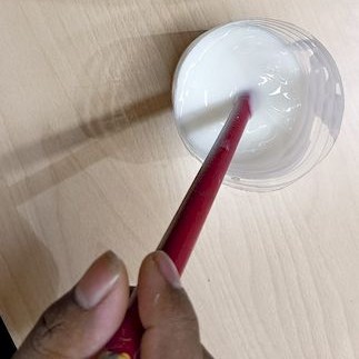
Before pouring, we applied a release agent inside the 3D printed mold cavity to prevent the silicone from bonding to the PLA surface. This would aid in easy demolding after curing.
The mixed silicone was then poured slowly into the mold cavity. Care was taken to pour from one corner, allowing the material to flow naturally and fill the mold uniformly. This technique also helped in pushing out any trapped air and ensured that fine details within the mold were filled accurately.
Curing and Demolding
The mold was left to cure undisturbed for the recommended time, as specified by the silicone manufacturer. After the curing period, the silicone had solidified well and conformed precisely to the shape of the mold cavity. The surface was smooth, and all design features were captured effectively.
The resulting negative mold was robust, clean, and ready for use in casting materials such as chocolate or resin.
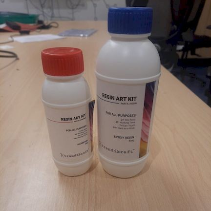
Preparation for Resin Casting
To cast resin into the silicone mold, we needed another round of precise measurement. Again, the 250 ml beaker was tared to ensure that only the resin's weight would be recorded.
Resin casting involved a two-part mixture using a 2:1 ratio of Part A (resin) to Part B (hardener). After measuring the required amount of Part A, we calculated and measured half that volume of Part B.
Accurate measurement is critical in resin casting. Any deviation from the ratio can result in incomplete curing, stickiness, or structural weakness. With careful weighing and verification, we ensured the proper amounts of both components.
Resin Mixing and Pouring
Once both components were measured, they were combined and mixed thoroughly. Mixing was done slowly and carefully to avoid introducing air bubbles. The mixed resin was then allowed to sit momentarily, letting any trapped air rise to the surface.
The mixed resin was poured into the silicone mold, starting from one side to allow a natural flow. This helped the resin fill every detail and reduced the chances of air pockets being trapped inside.
Resin Curing and Final Output
After the mold was filled, it was left to cure for the specified duration. The curing process was done undisturbed to ensure optimal strength and clarity in the final cast.
Once cured, the cast part was carefully demolded. The final product reflected a high-quality finish, with smooth surfaces and well-defined details, validating the effectiveness of the entire molding and casting process.
Conclusion
Despite the initial setback due to CNC tool failure, the project adapted efficiently by transitioning to 3D printing for mold fabrication. The use of precise measurement techniques, careful mixing, and attention to detail in the casting process led to the successful creation of both a high-quality silicone mold and a resin-cast final product. This experience underlined the importance of flexibility and accuracy in fabrication workflows.
Finally Leaving my files here
Version 2 - Mold Using Resin 3D Printing
Why We Redesigned the Mold
During the review process, the previously fabricated mold using FDM 3D printing was not approved because the layer lines produced by the FDM process were visible on the mold surface. These surface imperfections were transferred into the final casted part, affecting the overall finish and quality.
To improve the mold quality and obtain a smoother surface finish, we decided to redesign and fabricate the mold using a resin 3D printing process. Resin printing provides significantly higher resolution and smoother surfaces compared to FDM printing, making it more suitable for mold fabrication.
Reference Selection and CAD Design
To create the new mold design, I first collected a reference image from Pinterest. Based on this reference, the complete 3D model was recreated in Fusion 360. The design process involved creating the base geometry, defining the required mold cavity, and ensuring that the final model could be manufactured successfully using a resin 3D printer.

After completing the CAD design, the model was exported as an STL file for further processing in slicing software.
SketchFab View
Resin 3D Printer Used
For fabricating the mold, we used the Phrozen Sonic Mega 8K resin 3D printer. This machine offers extremely high printing resolution and is capable of producing smooth surfaces and fine details that are difficult to achieve using conventional FDM printing methods.
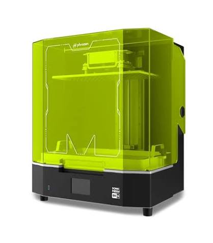
Phrozen Sonic Mega 8K Specifications
| Specification | Value |
|---|---|
| Machine Name | Phrozen Sonic Mega 8K |
| Technology | LCD Resin 3D Printing |
| LCD Resolution | 8K Mono LCD |
| Build Volume | 330 × 185 × 400 mm |
| XY Resolution | 43 µm |
| Layer Thickness | 0.01 – 0.30 mm |
| Light Source | Linear Projection LED Module |
| Slicing Software | Chitubox |
| File Format | .ctb |
| Application | High-Detail Prototyping, Mold Making, Miniatures, Industrial Parts |
Comparison Between FDM and Resin 3D Printing
The initial mold was fabricated using an FDM 3D printer. However, the visible layer lines and surface roughness produced by the FDM process affected the quality of the silicone mold and were transferred to the final casted component. To achieve a smoother mold surface and better casting quality, the mold was redesigned and fabricated using a resin 3D printer.
| Parameter | FDM 3D Printing | Resin 3D Printing |
|---|---|---|
| Printing Technology | Extrusion of Thermoplastic Filament | Photopolymer Resin Curing |
| Surface Finish | Visible Layer Lines | Very Smooth Surface Finish |
| Printing Accuracy | Moderate | High Precision |
| Detail Resolution | Limited for Small Features | Excellent Fine Detail Reproduction |
| Mold Quality | Requires Post Processing | Ready for Mold Making |
| Support Marks | Generally Minimal | Requires Careful Support Placement |
| Post Processing | Minimal | Cleaning and UV Curing Required |
| Best Application | Functional Prototypes | Molds and High-Detail Parts |
Based on these factors, resin printing was selected for the final mold fabrication because it provides significantly better surface quality, dimensional accuracy, and detail reproduction, which are essential requirements for molding and casting applications.
Chitubox Software
To prepare the mold for resin 3D printing, I used Chitubox, a slicing software specifically developed for LCD and resin-based 3D printers. The software is used to import STL files, configure printing parameters, generate supports, and prepare the final machine-readable file for the resin printer.
The latest version of Chitubox was downloaded from the official website and installed on the workstation used for the project.

Figure: Official Chitubox website used for downloading the slicing software.
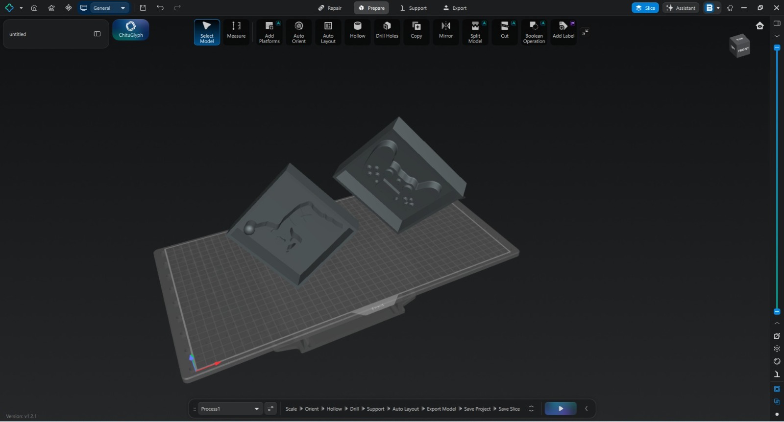
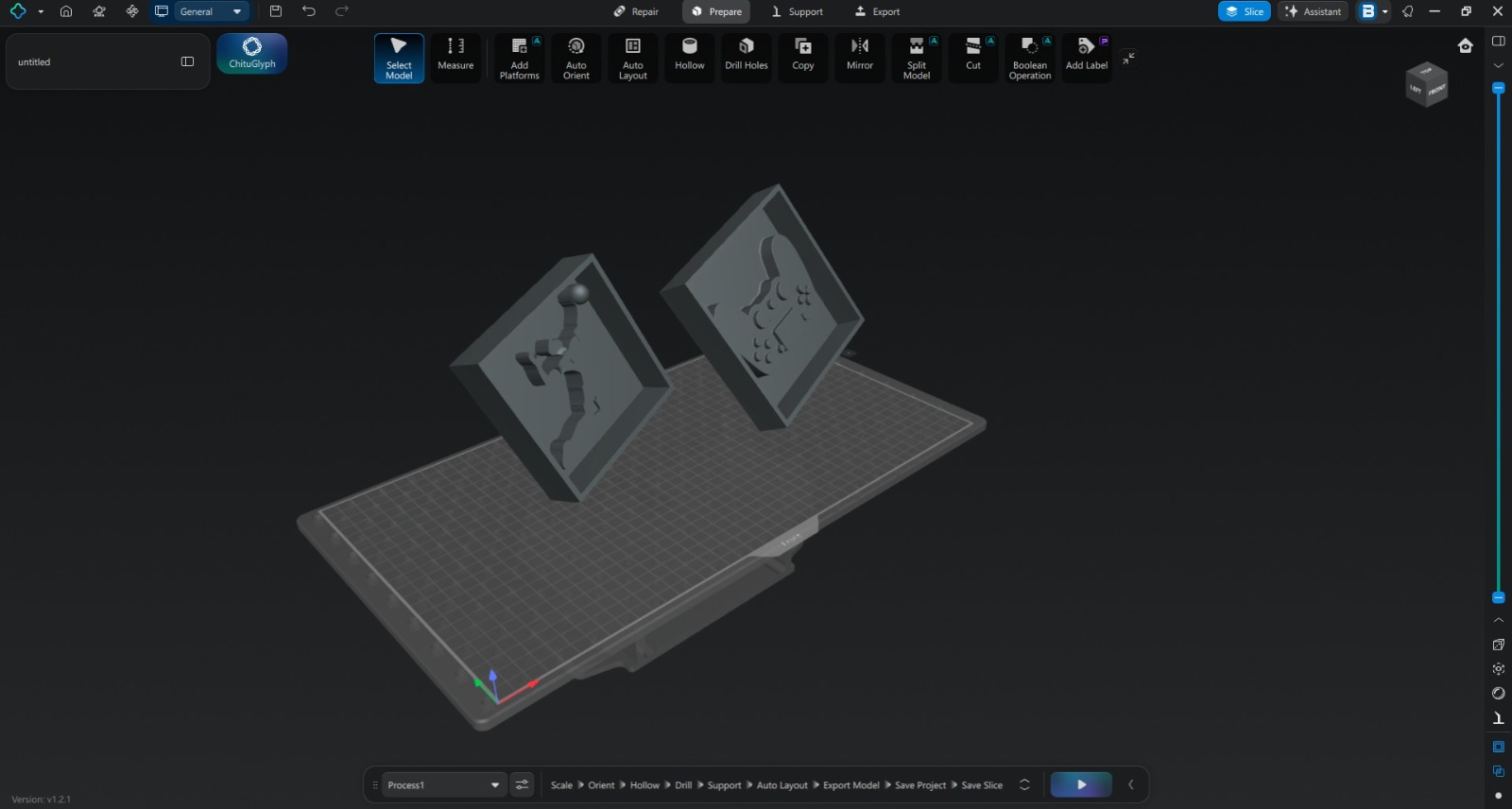
After installation, the software was launched and configured for the Phrozen Sonic Mega 8K resin printer. The STL model exported from Fusion 360 was then imported into Chitubox for further preparation.
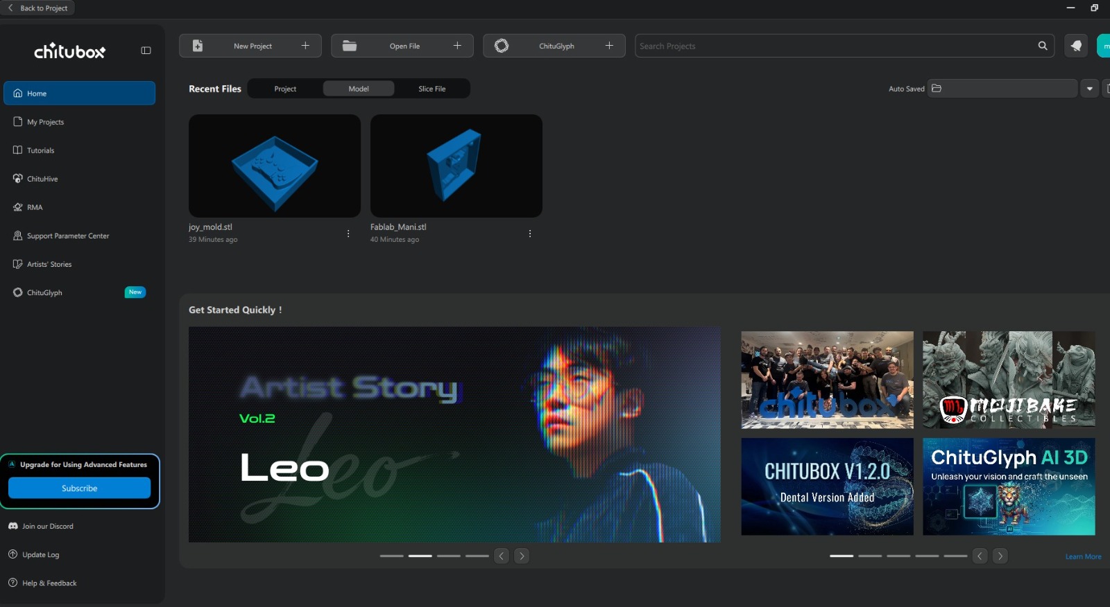
Figure: Chitubox software interface after importing the STL model.
The imported model was verified for scale and orientation before proceeding to the resin printing workflow.
Software Download: https://www.chitubox.com/
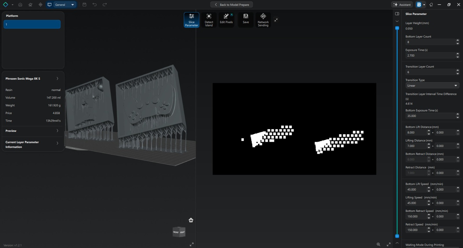
Model Slicing Using Chitubox
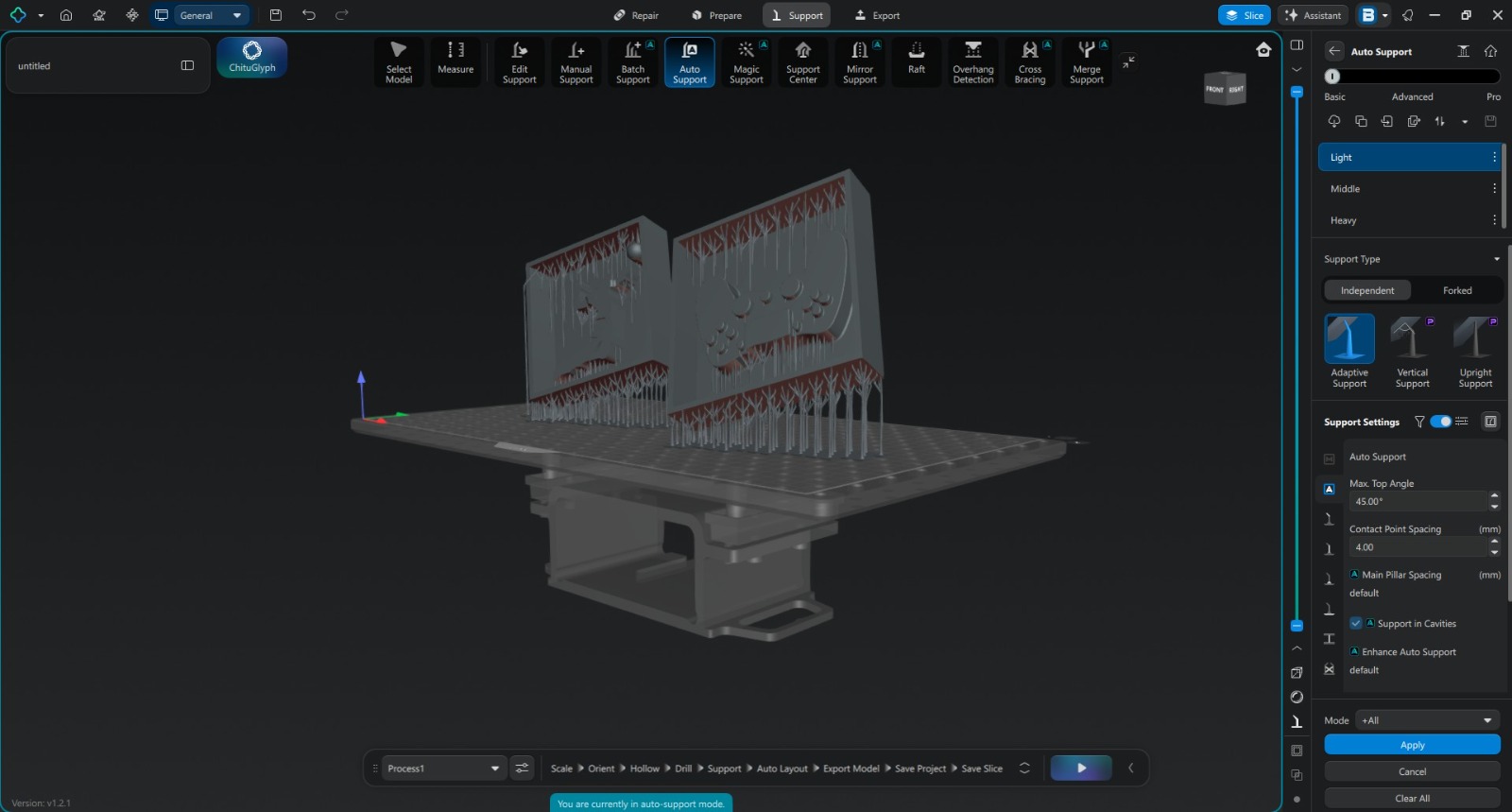
The STL file generated from Fusion 360 was imported into Chitubox slicer software. Chitubox was used to orient the model, generate support structures, and prepare the print file for the resin printer.
After verifying the model orientation and supports, the slicing process was completed and the final print file was transferred to the Phrozen Sonic Mega 8K printer for fabrication.
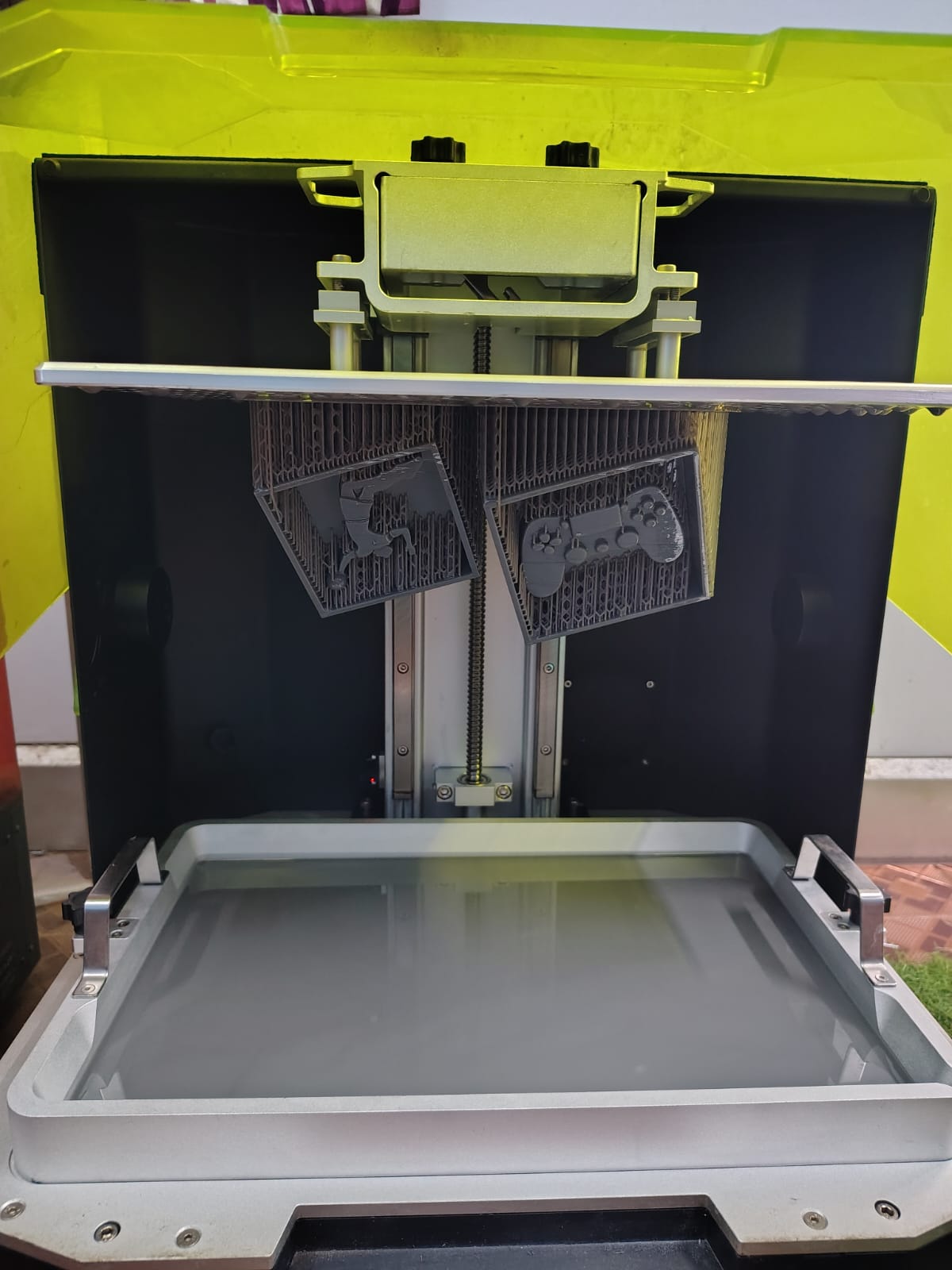
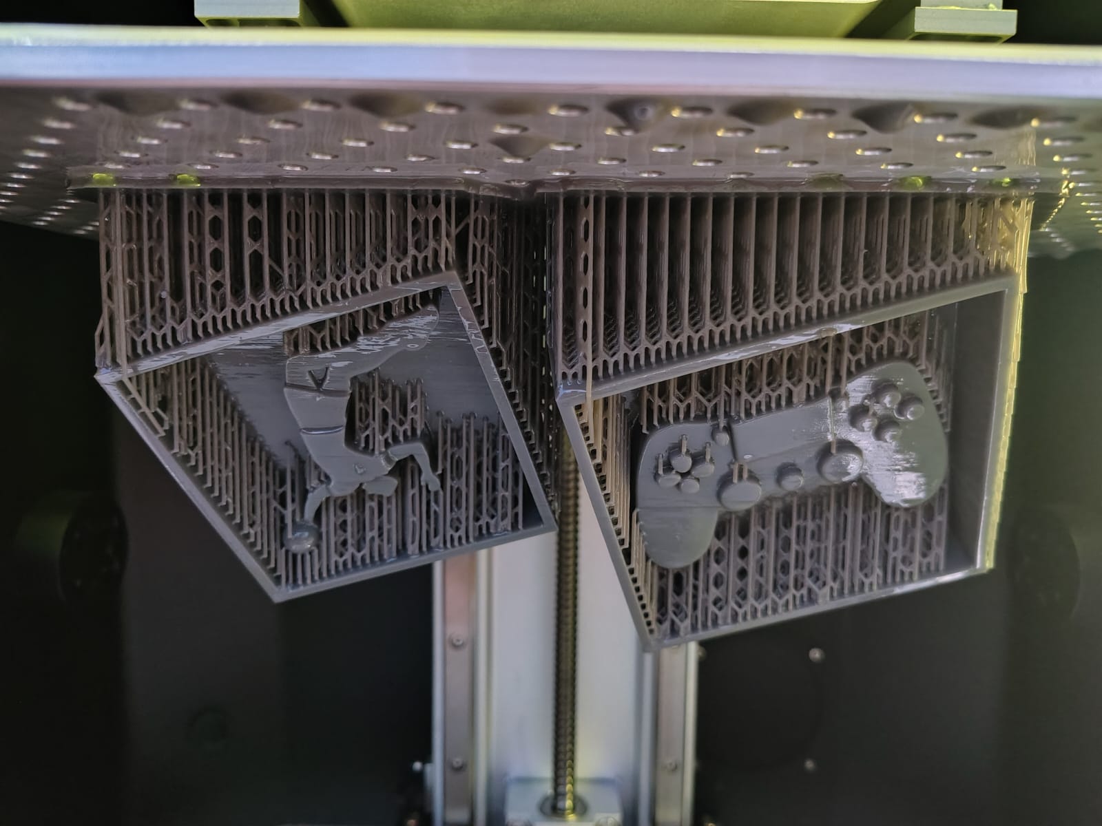
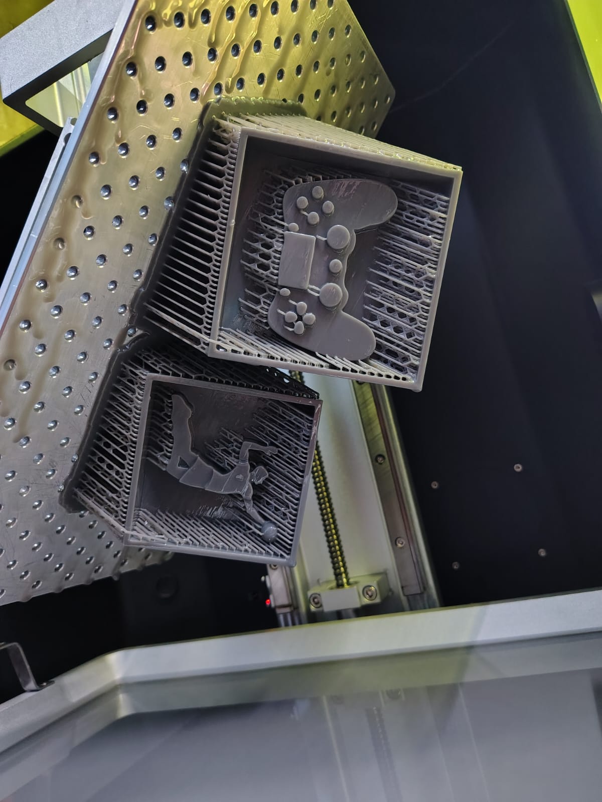
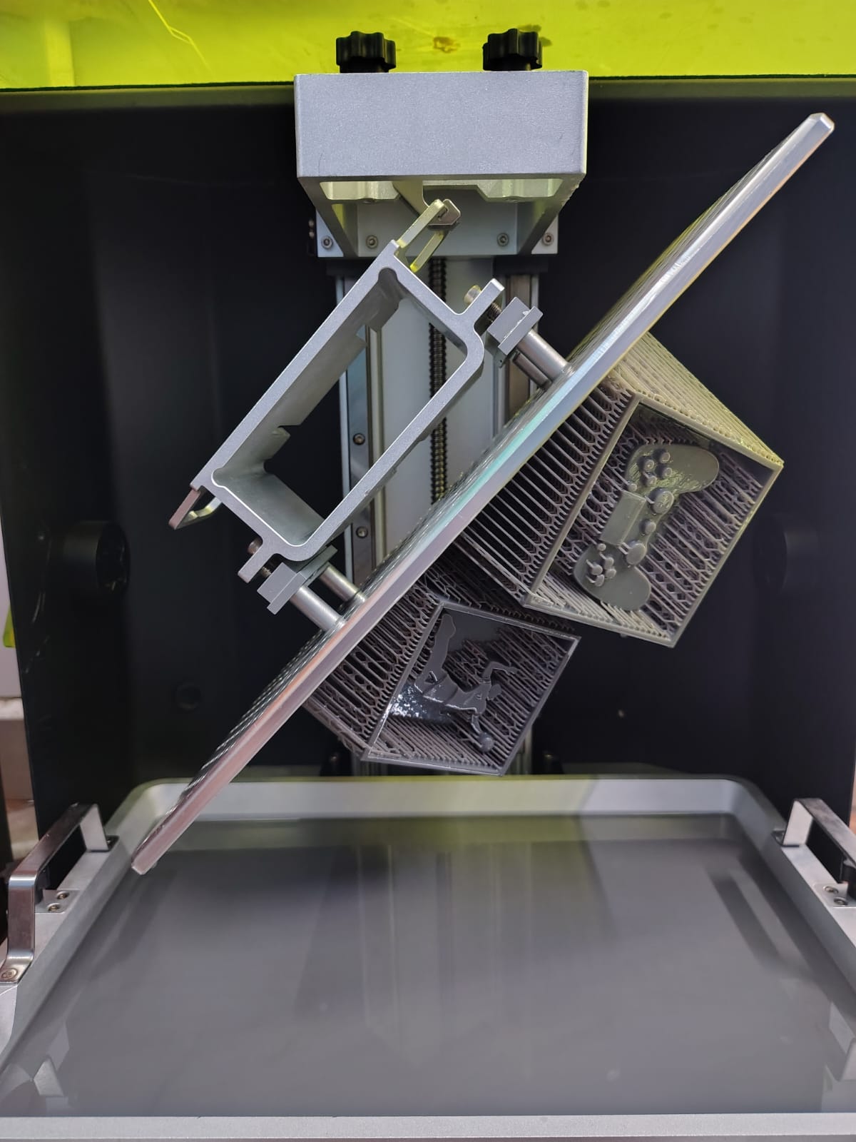
Resin Mold Fabrication
After slicing, the print job was started on the Phrozen Sonic Mega 8K resin printer. The printing process successfully produced the mold with excellent dimensional accuracy and a significantly smoother surface finish compared to the earlier FDM version.
After printing, the mold was cleaned and post-processed before being prepared for silicone molding operations.
Silicone Mold Fabrication
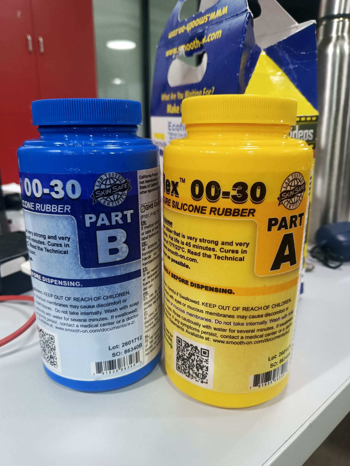
Ecoflex Silicone Rubber
For creating the flexible mold, Ecoflex Silicone Rubber Part A and Part B were used. Ecoflex is a platinum-cure silicone rubber known for its flexibility, durability, and ease of use in molding and casting applications.
The material was mixed in a 1:1 ratio by volume according to the manufacturer's instructions. After thorough mixing, the silicone was poured into the resin-printed mold and allowed to cure at room temperature to form a flexible negative mold.
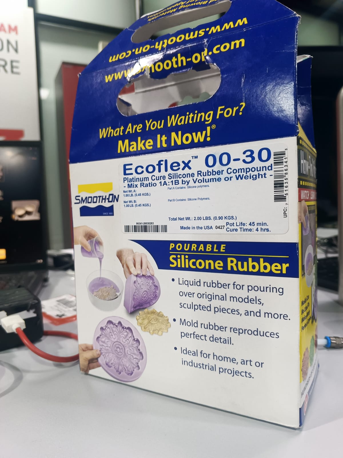
Ecoflex Technical Data Sheet
| Property | Value |
|---|---|
| Material Type | Platinum-Cure Silicone Rubber |
| Mix Ratio | 1A : 1B (by volume) |
| Pot Life | Approximately 30 Minutes |
| Cure Time | Approximately 4 Hours (Room Temperature) |
| Color | Translucent |
| Hardness | Shore 00-30 |
| Application | Mold Making, Special Effects, Casting |
The complete material safety and technical information was reviewed before handling the material to ensure safe mixing, curing, and mold fabrication procedures.
Technical Data Sheet: Download Ecoflex Technical Data Sheet
Silicone Mold Preparation
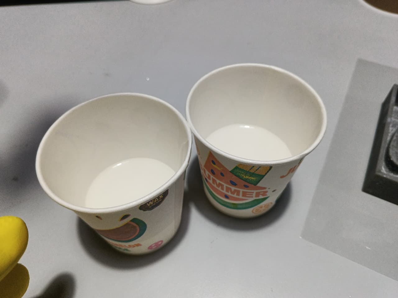
For creating the flexible mold, Ecoflex Silicone Rubber Part A and Part B were used. The manufacturer recommended a mixing ratio of 1:1.
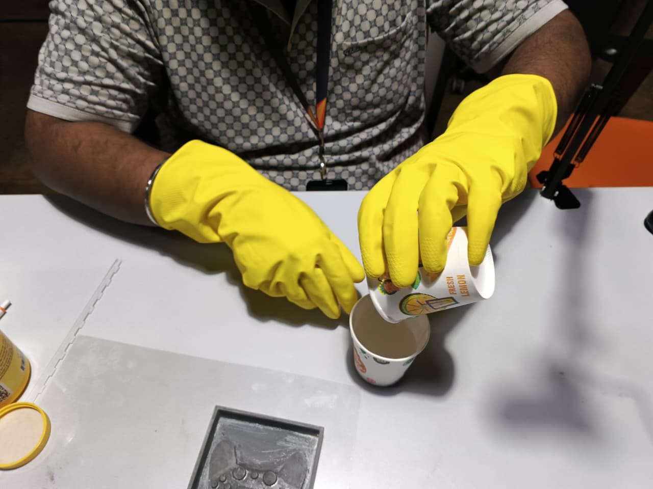
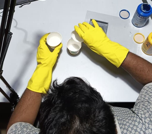
A 210 ml paper cup was used for measurement. Equal quantities of Part A and Part B were poured into separate cups and then combined into a mixing container.
The mixture was stirred thoroughly until a uniform consistency was achieved. Care was taken to avoid excessive air bubble formation during mixing.
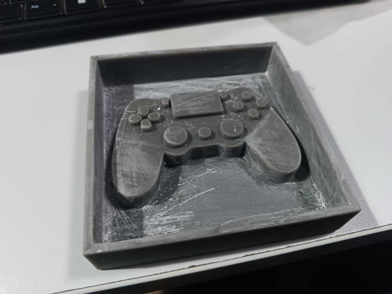
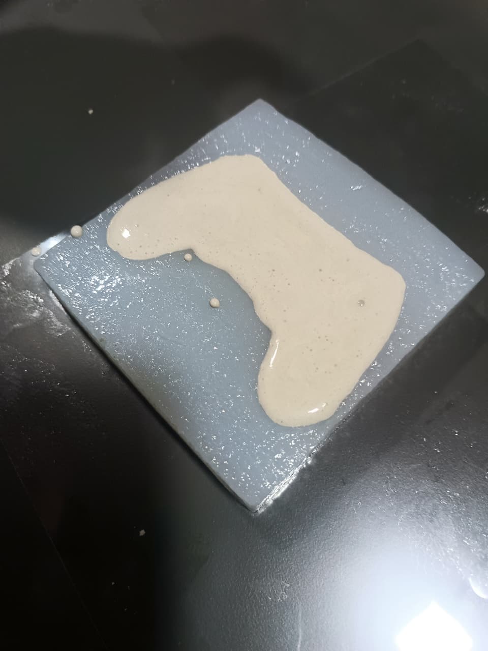
Silicone Pouring and Curing
The mixed silicone was carefully poured into the resin printed mold. The mold was gently tapped to release trapped air bubbles and ensure complete filling of the cavity.
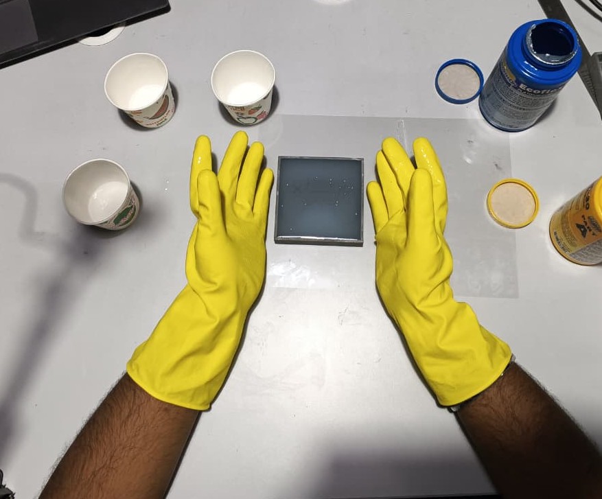
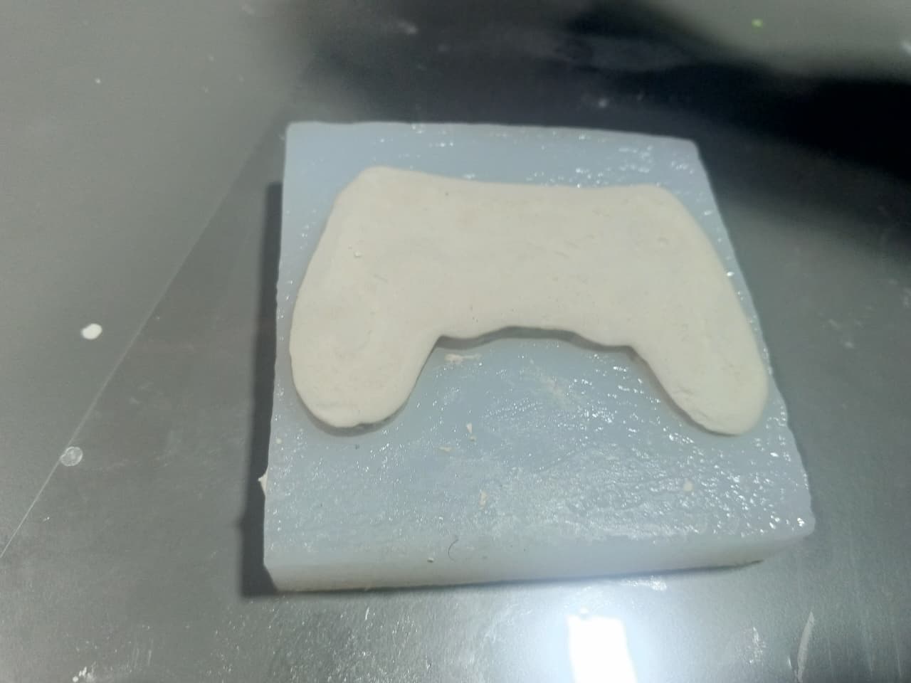
The silicone mold was then left undisturbed for approximately 12 hours at room temperature to achieve complete curing.
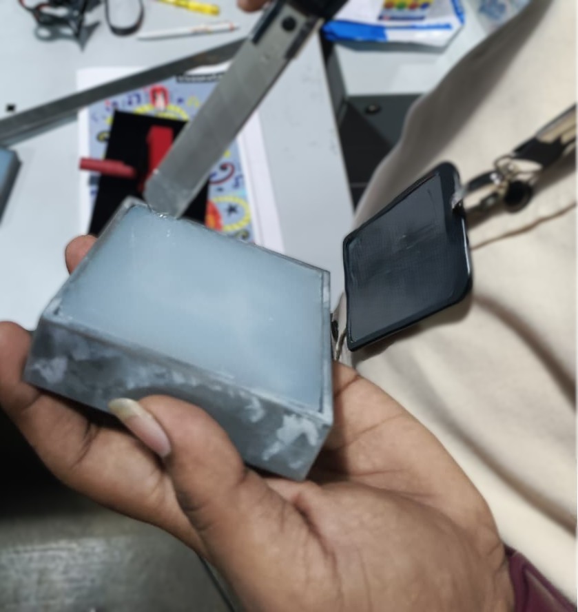
After curing, the silicone mold was carefully removed from the resin master mold and inspected for defects.
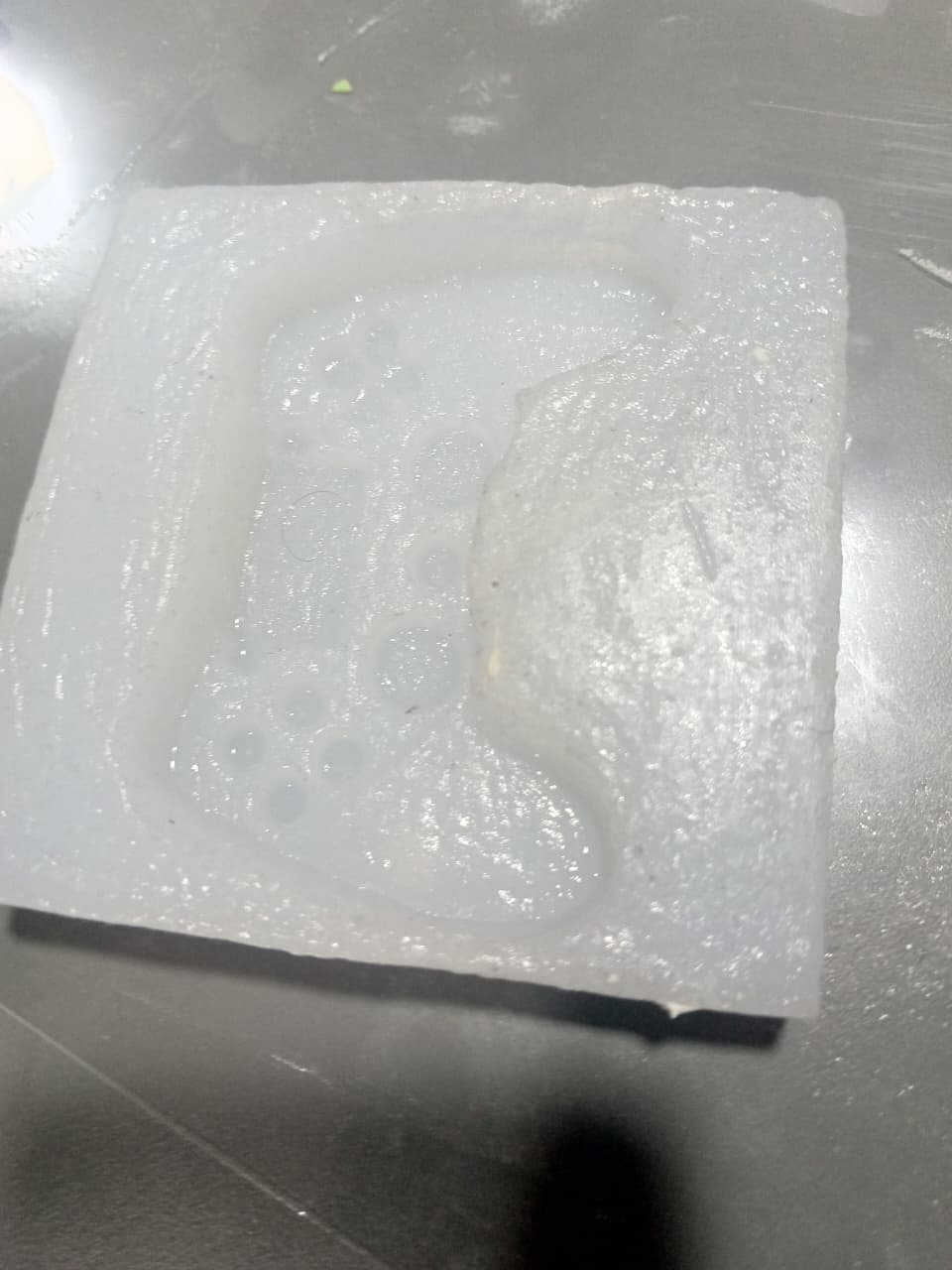
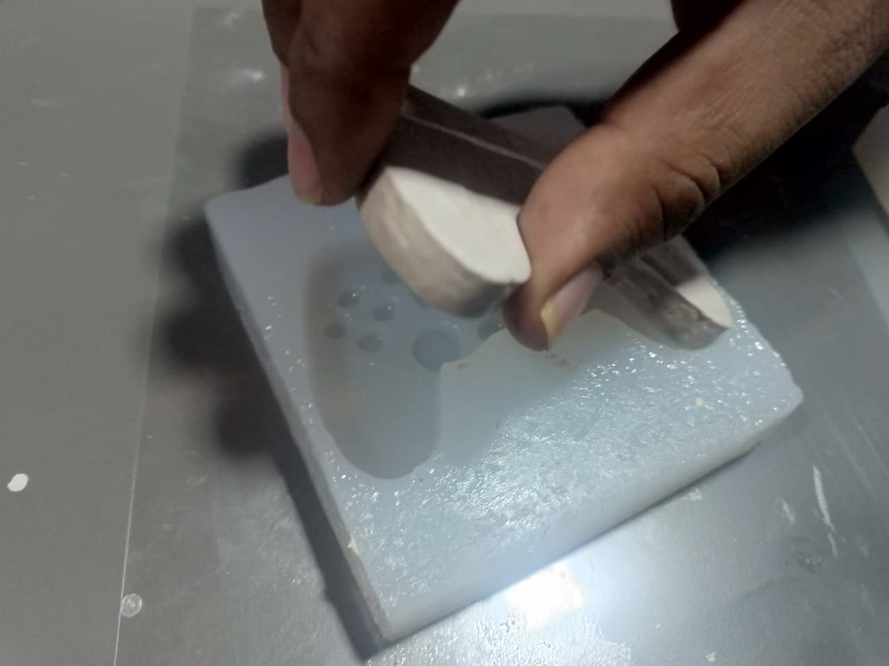
Plaster of Paris Casting
Once the silicone mold was prepared, Plaster of Paris (POP) was selected as the casting material.
A 60 ml paper cup was used for measuring the material quantities. Approximately three-fourths of a cup of Plaster of Paris powder was mixed with one-fourth cup of water.
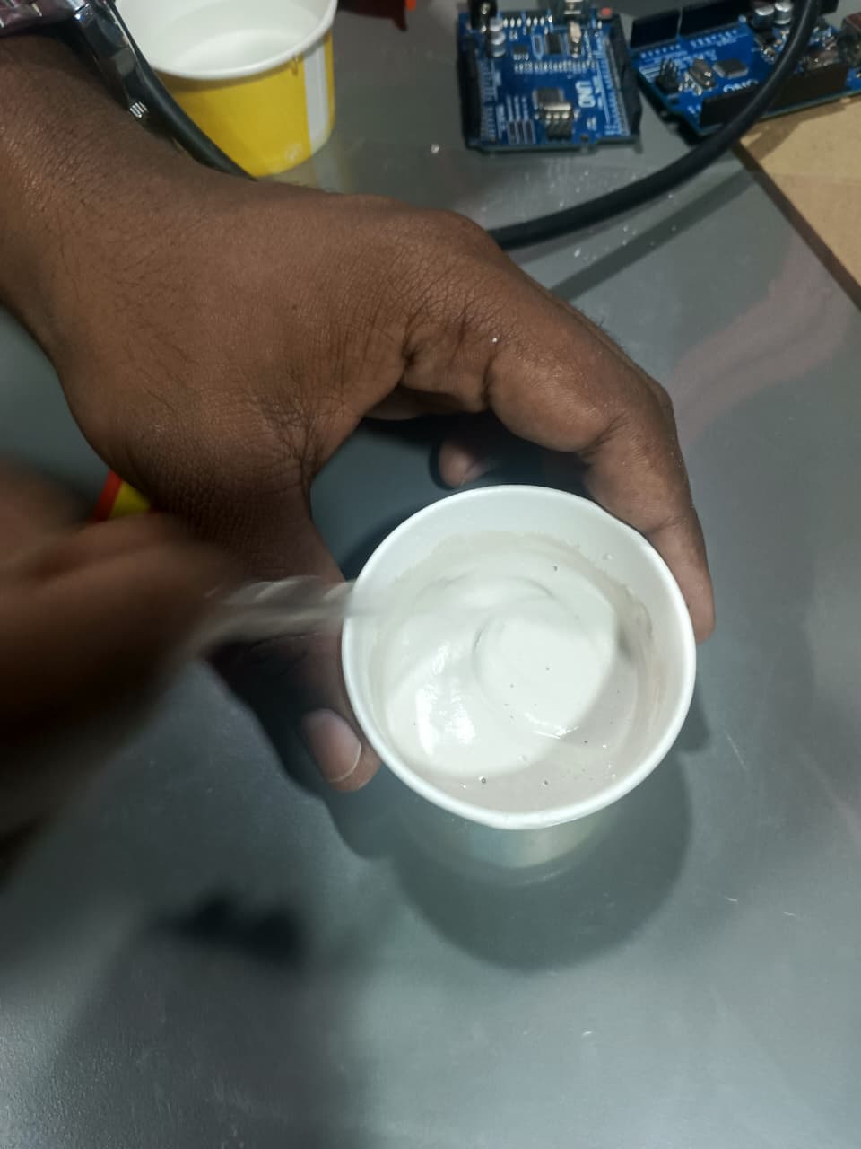
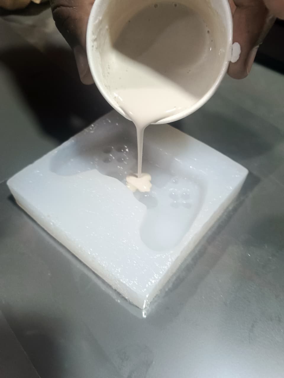
The mixture was stirred thoroughly until a smooth consistency was obtained and then poured into the silicone mold cavity.
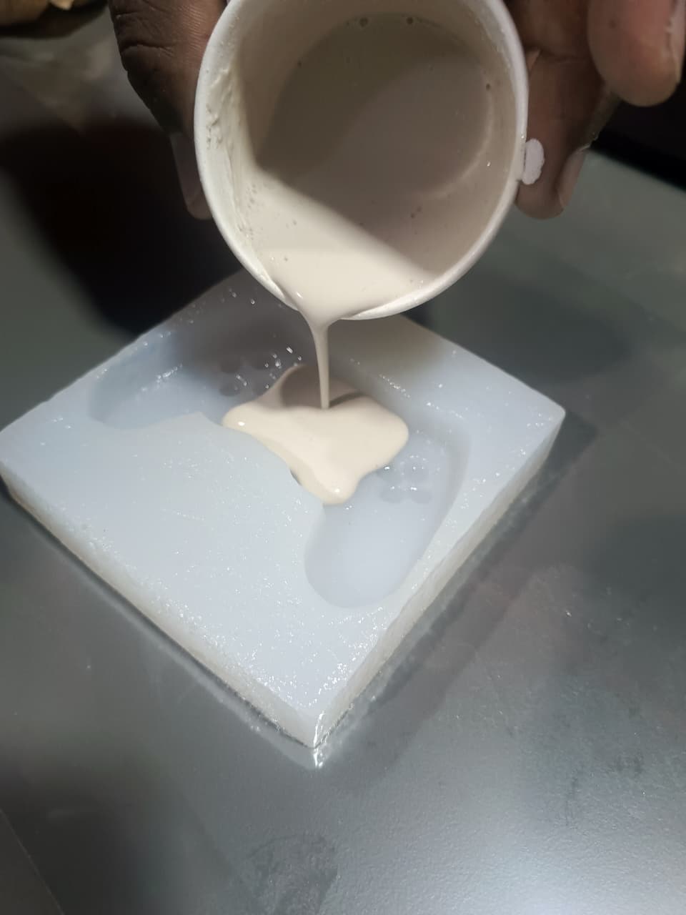
The mold was left for approximately two hours to allow the plaster to solidify completely.
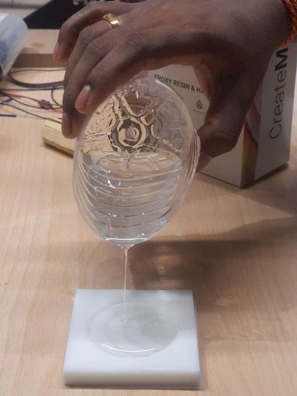
Final Output and Observations
After curing, the casted component was carefully removed from the silicone mold. The overall geometry and dimensional features were successfully reproduced.
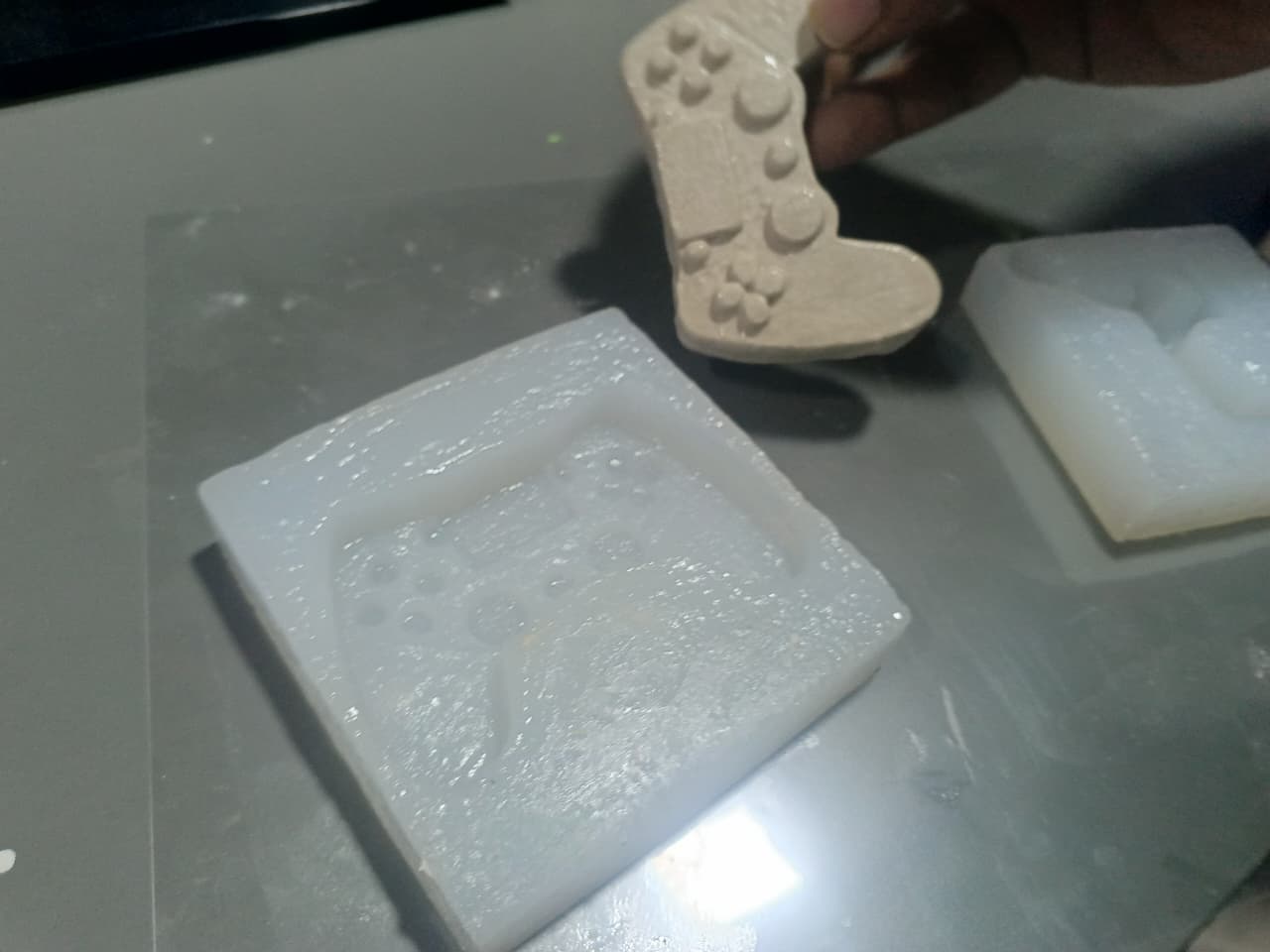
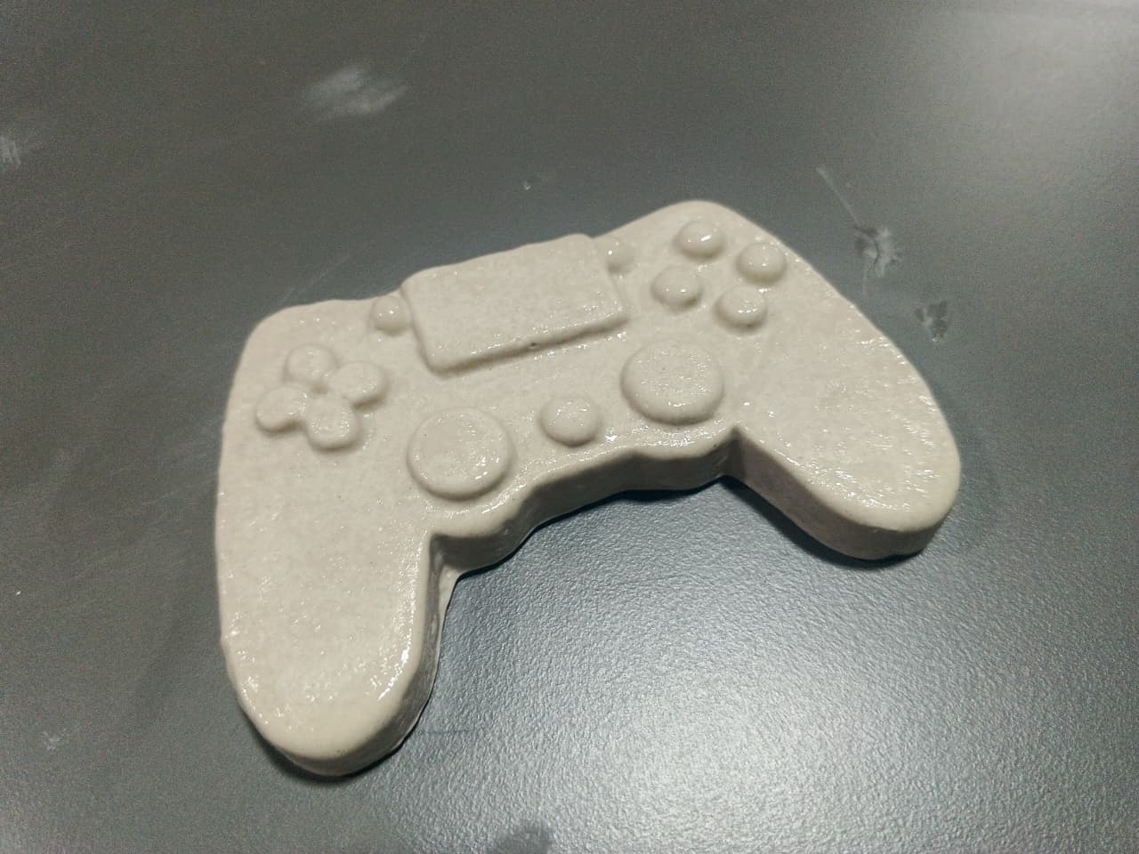
Although the casting process was successful, minor surface imperfections were observed. This was primarily caused by incomplete curing of certain regions of the silicone mold due to the relatively cool room temperature during the curing process.
Despite these minor defects, the final casting demonstrated the effectiveness of resin-based mold fabrication and silicone molding for producing detailed cast components.
Hero Shot
The final outcome of this assignment demonstrates the complete molding and casting workflow, beginning with a high-resolution resin 3D printed master mold, followed by the fabrication of a flexible silicone mold using Ecoflex silicone rubber, and finally producing a casted object using Plaster of Paris. The resin printed mold provided excellent surface quality and fine detail reproduction, making it highly suitable for mold-making applications.
The silicone mold successfully captured the intricate features of the resin master, while the final cast accurately reproduced the original geometry. This workflow highlights the advantages of combining resin 3D printing, silicone molding, and casting techniques to create detailed and repeatable components.
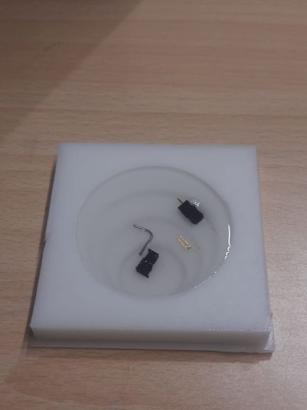
Resin Printed Master Mold
Final Plaster of Paris Cast
Figure: Final resin-printed mold and the completed casted component produced using the molding and casting workflow.
Learning Summary
- Learned the complete workflow of resin mold fabrication.
- Designed a custom mold using Fusion 360.
- Used Chitubox for resin print preparation and slicing.
- Operated a Phrozen Sonic Mega 8K resin printer.
- Prepared and mixed Ecoflex silicone in a 1:1 ratio.
- Created a flexible silicone mold from a resin master.
- Performed Plaster of Paris casting.
- Observed the influence of curing conditions on final mold quality.
- Compared FDM and resin printing methods for mold fabrication.
Downloads
The design files, printable model files, and material documentation used throughout this molding and casting workflow can be downloaded from the links below.
| S.No | File Name | Description | Download |
|---|---|---|---|
| 1 | Resin_Mold_Design.f3d | Fusion 360 source design file used for creating the resin printed master mold. | Download |
| 2 | Resin_Mold_STL.stl | STL file exported from Fusion 360 and used for resin printing in Chitubox. | Download |
| 3 | Ecoflex_TDS.pdf | Technical Data Sheet (TDS) and safety information for Ecoflex Silicone Rubber. | Download |