- Week 1 : Project Management
- Week 2 : Computer-aided
- Week 3 : Computer Controlled Cutting
- Week 4 : Embedded Programming
- Week 5 :3D Scanning and Printing
- Week 6 : Electronic Design
- Week 7 : Computer Controlled Machining
- Week 8 : Electronics Production
- Week 9 : Input Devices
- Week 10 : Output Devices
- Week 11 : Networking and Communication
- Week 12 : Mechanical Design and Machine Design
- Week 14 : Molding and Casting
- Week 15 : Interface and Application Programming
- Week 16 : System Integeration
- Week 17 : Wildcard Week
- Week 18 : Applications and Implications, Project Development
- Week 19 : Invention, Intellectual property and Income
- Week 20 : FInal Project Requirements
Week 10 : Output Devices
Objectives of the Week
- Linked to the group assignment page.
- Documented how you determined power consumption of an output device with your group.
- Documented what you learned from interfacing output device(s) to microcontroller and controlling the device(s).
- Linked to the board you made in a previous assignment or documented your design and fabrication process if you made it.
- Explained the programming process/es you used.
- Explained any problems you encountered and how you fixed them.
- Included original source code and any new design files.
- Included a 'hero shot' of your board.
Group Assignment Contribution
For More about Group Assignment
Individual Assignment Contribution
LCD Display 16*2
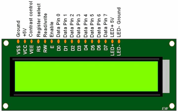
16x2 LCD Display Datasheet
Usage
Liquid Crystal Displays (LCDs) are widely used in electronic projects, embedded systems, consumer electronics, industrial equipment, and automotive dashboards. These displays work by using liquid crystals that align to block or allow light through. Common LCD types include character LCDs (like 16x2) and graphic LCDs. They are often controlled using microcontrollers like Arduino, Raspberry Pi, or STM32 and are suitable for displaying text, menus, and basic graphics.
Advantages
- Low Power Consumption: LCDs consume less power, making them ideal for battery-operated devices.
- Wide Availability: Available in various sizes and formats (character, graphic, TFT).
- Readable in Sunlight: Many LCDs have good visibility under direct light.
- Cost-Effective: Affordable and widely used in educational and industrial settings.
- Simple Interface: Easy to interface with most microcontrollers using parallel or I2C communication.
Disadvantages
- Limited Viewing Angles: LCDs tend to have narrow viewing angles compared to newer technologies.
- Lower Contrast: Not as vibrant or sharp as OLED displays.
- Slow Response Time: May not be suitable for fast-refresh applications like gaming or animations.
- Backlight Dependency: Requires a backlight for visibility in the dark, increasing power consumption.
OLED Display
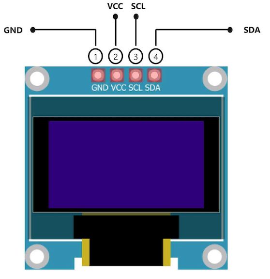
OLED Datasheet
Usage
Organic Light Emitting Diode (OLED) displays are modern, energy-efficient screens used in smartphones, smartwatches, embedded systems, and premium consumer electronics. OLEDs emit light directly from the pixels, eliminating the need for a backlight. Common types include 0.96" and 1.3" I2C OLEDs, frequently used with microcontrollers for displaying text, icons, and small graphics.
Advantages
- High Contrast Ratio: Displays true black by turning off pixels entirely.
- Wide Viewing Angles: Maintains visibility and clarity from multiple angles.
- Thin and Lightweight: Extremely compact, ideal for space-constrained applications.
- Faster Response Time: Excellent for animations and real-time interfaces.
- Low Power for Dark Themes: Consumes less power when displaying black or fewer lit pixels.
Disadvantages
- Cost: Generally more expensive than LCD displays of similar size.
- Burn-in Risk: Static images over long periods may cause pixel burn-in.
- Lower Brightness in Sunlight: Can be less readable under direct sunlight than LCDs.
- Limited Lifespan: Organic compounds degrade over time, especially blue pixels.
MG995 Servo Motor
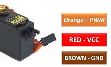
MG995R datasheet
Usage
The MG995 is a popular high-torque digital servo motor commonly used in robotics, RC cars, automation systems, and DIY mechanical projects. It provides precise control over angular position using PWM signals and is compatible with microcontrollers like Arduino. It's ideal for controlling joints, arms, and mechanisms in robotic applications requiring torque and durability.
Advantages
- High Torque Output: Offers up to 10 kg-cm of torque, suitable for heavy mechanical loads.
- Metal Gears: Durable gear assembly ensures longer operational life and resistance to wear.
- Wide Compatibility: Easily integrated with Arduino, Raspberry Pi, and other platforms.
- Digital Control: Provides precise angle control using PWM.
- Affordable: Budget-friendly for hobbyists and educational use.
Disadvantages
- No Continuous Rotation: Limited to 180° movement, not suitable for full rotation tasks.
- Power Hungry: Requires a stable 5–6V power supply with sufficient current.
- Vibration and Noise: Can be noisy and jittery under load or incorrect signal.
- Weight: Slightly bulky for very compact applications.
Making Interface with Microcontroller
From the last week, we have done a Input board that used for controlling the Joystick with microcontroller
Now in thie week, we have done a Output board that used for controlling the Oled with microcontroller
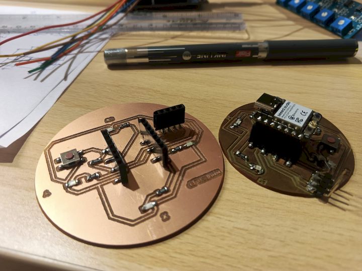
We have used this board for our Electronic production now we are gonna use the same for the Output device by attaching it with OLed Display
Click here to how I made this BoardProgramming Processs
First we have to include the necessary libraries from the Arduino IDE
#include <WiFi.h>This includes the WiFi library necessary for ESP32 to connect to a wireless network.
#include <Wire.h>This includes the I2C communication library, which is used for interfacing with the OLED display.
#include <Adafruit_GFX.h>This is the core graphics library from Adafruit used for drawing text, shapes, and images on displays.
#include <Adafruit_SSD1306.h>This library is specifically for the SSD1306-based OLED displays to control how content is displayed.
#include <time.h>This includes time-related functions, especially for syncing and formatting time from the internet using NTP (Network Time Protocol).
#define SCREEN_WIDTH 128
#define SCREEN_HEIGHT 64
Defines the width and height of the OLED display in pixels.
Adafruit_SSD1306 display(SCREEN_WIDTH, SCREEN_HEIGHT, &Wire, -1);Initializes the OLED display object with defined width, height, I2C communication using Wire, and no reset pin (-1).
const char* ssid = "Muhesh";
const char* password = "876543219";
Stores the WiFi network name (SSID) and password as constant character pointers.
int currentScreen = 0;
unsigned long lastSlideTime = 0;
const int slideInterval = 3000;
Variables used to manage screen transitions: the current screen index, the last time the screen changed, and the slide interval (3 seconds).
void connectToWiFi()This function attempts to connect the ESP32 to the specified WiFi network.
WiFi.begin(ssid, password);Starts the WiFi connection using the given SSID and password.
while (WiFi.status() != WL_CONNECTED && retry < 40)Retries the connection 40 times with a 500ms delay between each attempt.
void setupTime()This function sets up internet time using NTP servers with GMT offset for IST (19800 seconds).
configTime(19800, 0, "pool.ntp.org", "time.nist.gov");Configures the ESP32 to get the time from internet time servers with Indian Standard Time offset.
void setup()This is the main setup function which runs once. It initializes the serial monitor, OLED display, WiFi connection, and time sync.
Serial.begin(115200);Begins serial communication at 115200 baud rate for debugging purposes.
if (!display.begin(SSD1306_SWITCHCAPVCC, 0x3C))Initializes the OLED screen with I2C address 0x3C. If it fails, it prints an error message and enters an infinite loop.
display.clearDisplay();
display.display();
Clears the OLED screen and refreshes it to make it blank initially.
String getTimeString()Fetches the current time from the ESP32's internal clock and formats it as HH:MM:SS.
String getDateString()Returns the current date in DD-MM-YYYY format.
String getDayString()Returns the current day of the week (e.g., Monday, Tuesday).
void drawIndicators(int activeIndex)Draws three indicator dots at the bottom of the screen to show which screen (time, date, or day) is currently active. The active screen dot is drawn larger.
void loop()This is the main loop function that runs continuously. It updates the OLED screen every 3 seconds to show either the time, date, or day.
if (currentMillis - lastSlideTime >= slideInterval)Checks if 3 seconds have passed since the last screen change to proceed with the next screen.
switch (currentScreen)Determines which data (time, date, or day) to display based on the current screen index.
display.setTextSize(2);Sets the size of the text to be drawn on the OLED screen.
display.setCursor((SCREEN_WIDTH - (textToShow.length() * 12)) / 2, yPos);Calculates the horizontal position to center the text on the screen and sets the cursor position accordingly.
display.print(textToShow);Displays the selected string (time, date, or day) on the OLED screen.
drawIndicators(currentScreen);Displays the current screen indicator dots to indicate the active screen visually.
currentScreen = (currentScreen + 1) % 3;Cycles the screen index between 0, 1, and 2 repeatedly to rotate through time, date, and day.
Complete Code
        #include <WiFi.h>
        #include <Wire.h>
        #include <Adafruit_GFX.h>
        #include <Adafruit_SSD1306.h>
        #include <time.h>

        #define SCREEN_WIDTH 128
        #define SCREEN_HEIGHT 64
        Adafruit_SSD1306 display(SCREEN_WIDTH, SCREEN_HEIGHT, &Wire, -1);

        const char* ssid = "Muhesh";
        const char* password = "876543219";

        int currentScreen = 0;
        unsigned long lastSlideTime = 0;
        const int slideInterval = 3000;

        void connectToWiFi() {
        Serial.print("Connecting to WiFi");
        WiFi.begin(ssid, password);
        int retry = 0;
        while (WiFi.status() != WL_CONNECTED && retry < 40) {
            delay(500);
            Serial.print(".");
            retry++;
        }
        if (WiFi.status() == WL_CONNECTED) {
            Serial.println("\nWiFi connected");
            Serial.print("IP: ");
            Serial.println(WiFi.localIP());
        } else {
            Serial.println("\nFailed to connect WiFi");
        }
        }

        void setupTime() {
        configTime(19800, 0, "pool.ntp.org", "time.nist.gov");
        struct tm timeinfo;
        if (!getLocalTime(&timeinfo)) {
            Serial.println("Failed to get time");
        } else {
            Serial.println("Time synced");
        }
        }

        void setup() {
        Serial.begin(115200);

        if (!display.begin(SSD1306_SWITCHCAPVCC, 0x3C)) {
            Serial.println("OLED init failed");
            while (true);
        }
        display.clearDisplay();
        display.display();

        connectToWiFi();
        setupTime();
        }

        String getTimeString() {
        struct tm timeinfo;
        if (!getLocalTime(&timeinfo)) return "No Time";
        char buf[10];
        strftime(buf, sizeof(buf), "%H:%M:%S", &timeinfo);
        return String(buf);
        }

        String getDateString() {
        struct tm timeinfo;
        if (!getLocalTime(&timeinfo)) return "No Date";
        char buf[12];
        strftime(buf, sizeof(buf), "%d-%m-%Y", &timeinfo);
        return String(buf);
        }

        String getDayString() {
        struct tm timeinfo;
        if (!getLocalTime(&timeinfo)) return "No Day";
        char buf[12];
        strftime(buf, sizeof(buf), "%A", &timeinfo);
        return String(buf);
        }

        void drawIndicators(int activeIndex) {
        int dotY = SCREEN_HEIGHT - 10;
        int startX = (SCREEN_WIDTH - (3 * 16)) / 2;

        for (int i = 0; i < 3; i++) {
            if (i == activeIndex) {
            display.fillCircle(startX + i * 16, dotY, 5, SSD1306_WHITE);
            } else {
            display.fillCircle(startX + i * 16, dotY, 2, SSD1306_WHITE);
            }
        }
        }

        void loop() {
        unsigned long currentMillis = millis();

        if (currentMillis - lastSlideTime >= slideInterval) {
            lastSlideTime = currentMillis;

            String textToShow;
            switch (currentScreen) {
            case 0: textToShow = getTimeString(); break;
            case 1: textToShow = getDateString(); break;
            case 2: textToShow = getDayString(); break;
            }

            display.clearDisplay();
            display.setTextSize(2);
            display.setTextColor(SSD1306_WHITE);
            int yPos = (SCREEN_HEIGHT - 16) / 2;
            display.setCursor((SCREEN_WIDTH - (textToShow.length() * 12)) / 2, yPos);
            display.print(textToShow);

            drawIndicators(currentScreen);

            display.display();

            currentScreen = (currentScreen + 1) % 3;
        }
        }
Interfaceing the OLED Display with PCB board
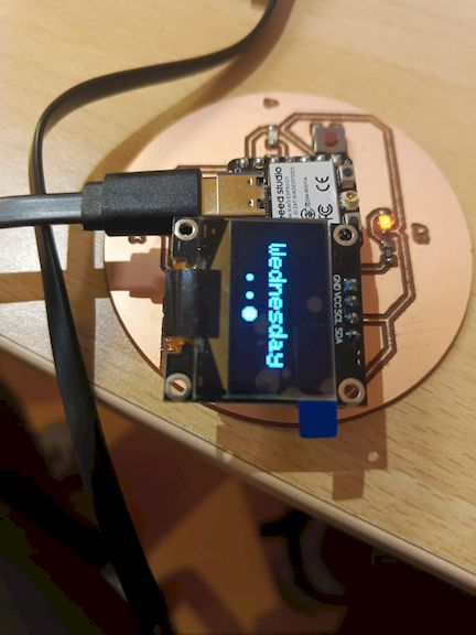
After uploading the code to Esp32c3 I have determined to to show it like a watch so I have planned to show time date and day in the OLED display like a sliding with dealy of 3 seconds
This can be done by doing the wifi connect with the online interface and then syncing the time from the NTP server