- Week 1 : Project Management
- Week 2 : Computer-aided
- Week 3 : Computer Controlled Cutting
- Week 4 : Embedded Programming
- Week 5 :3D Scanning and Printing
- Week 6 : Electronic Design
- Week 7 : Computer Controlled Machining
- Week 8 : Electronics Production
- Week 9 : Input Devices
- Week 10 : Output Devices
- Week 11 : Networking and Communication
- Week 12 : Mechanical Design and Machine Design
- Week 14 : Molding and Casting
- Week 15 : Interface and Application Programming
- Week 16 : System Integeration
- Week 17 : Wildcard Week
- Week 18 : Applications and Implications, Project Development
- Week 19 : Invention, Intellectual property and Income
- Week 20 : FInal Project Requirements
Week 8: Electronic Production
This week describes my understanding of how to use Input Devices. It also includes how to generate an analog output (PWM) using pin 9, how to use an oscilloscope and multimeter for analysis, and how to integrate different sesnor with the microcontroller.
Objectives of the Week
Group Assignment Contribution
Through the group assignment, I learned how machine limitations directly influence PCB design decisions. Understanding trace width, clearance, tool diameter, and manufacturing constraints helped me create PCB layouts that are more reliable and easier to fabricate. I also gained a better understanding of the differences between in-house PCB milling and professional board-house fabrication workflows.
For More about Group AssignmentAs part of this week's group assignment, I contributed by defining the design rules tailored for our in-house PCB fabrication process.
Overview of Wegstr CNC Machines
CNC (Computer Numerical Control) machines have significantly transformed how we approach manufacturing and prototyping by offering high precision and repeatability. Among the trusted names in this domain is Wegstr, a Czech-based company recognized for its compact and user-friendly CNC milling machines. In this section, I’ll be sharing insights into the core features, available models, and use cases of Wegstr CNC machines, and why they’re a reliable choice for educational and small-scale manufacturing setups.
Main Features of Wegstr CNC Machines
Wegstr machines come equipped with multiple features that make them efficient and easy to use. The table below outlines the main technical specifications that set them apart from other desktop CNC machines:
| Feature | CNC Wegstr LIGHT | CNC Wegstr DARK |
|---|---|---|
| Spindle Speed | 11,000 RPM | 11,000 RPM |
| Working Area | 140 x 200 mm | 140 x 200 mm |
| Total Power Input | 30 W | 30 W |
| Rated Input Power of Spindle | 25 W | 25 W |
| Maximal Height Under Spindle | 40 mm | 40 mm |
| Axis Speed (X, Y, Z) | 170 mm/min | 170 mm/min |
| Tool Holding Diameter | 3.175 mm | 3.175 mm |
| Software Compatibility | Windows, Mac, Linux | Windows, Mac, Linux |
| Price | €3,190 | €3,190 |
These features make Wegstr CNC machines suitable for a wide range of applications, from PCB milling to intricate designs in various materials.
Types of Wegstr CNC Machines
Wegstr offers different types of CNC machines tailored to specific needs and applications. Below is a comparison table of the various types available:
| Type | Description | Ideal For |
|---|---|---|
| CNC Wegstr LIGHT | A versatile machine for light materials. | Hobbyists and small workshops. |
| CNC Wegstr DARK | Designed for heavier materials and industrial use. | Professional and industrial applications. |
| CNC Milling Machine | General-purpose milling machine. | Various milling tasks. |
| CNC PCB Milling Machine | Specialized for PCB fabrication. | Electronics and PCB prototyping. |
Each type of machine is designed to cater to different user requirements, ensuring that there is a suitable option for everyone, from hobbyists to professionals.
Applications of Wegstr CNC Machines
Wegstr CNC machines are widely used across various industries due to their versatility and precision. They are particularly popular in:
– Electronics: For milling PCBs and creating intricate electronic components.
– Woodworking: Ideal for crafting detailed wooden designs and furniture.
– Metalworking: Capable of milling metals for parts in machinery and automotive applications.
– Prototyping: Used in R&D for rapid prototyping of new designs.
Individual Assignment
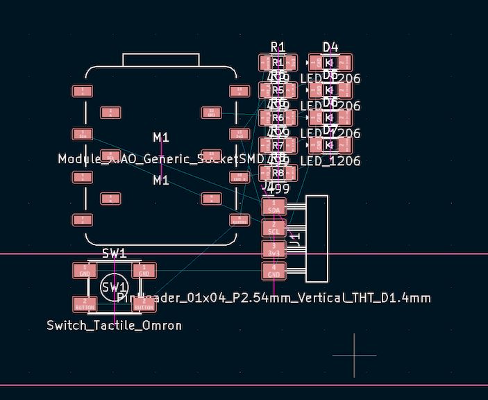
As we have done form the PCB Design 2 weeks back we are gonna bring that back in KiCAD
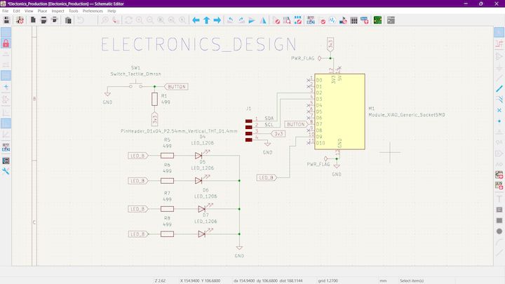
This is the Schematic Diagram. We have done in the last week what was the actual concept is to glow up the Light from one by one like a Circular thing. What I have done is like giving the connection to the D4 pin and then Individually blinking with Time delays
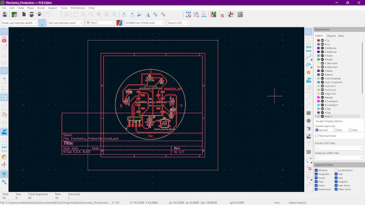
Now What we are gonna do this change to the PCB Production mode and then Import the Module
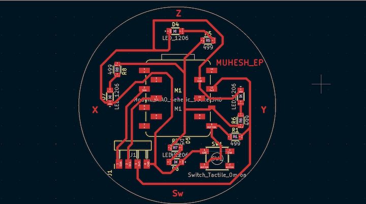
In the Previous week, we have done this Assembling all the things what we are gonna do is Just make some adjustments to Get this into Real World
Step 1
In our Machine there will be a Track width Constraint. So what we need to do is to change the track width to 0.6mm
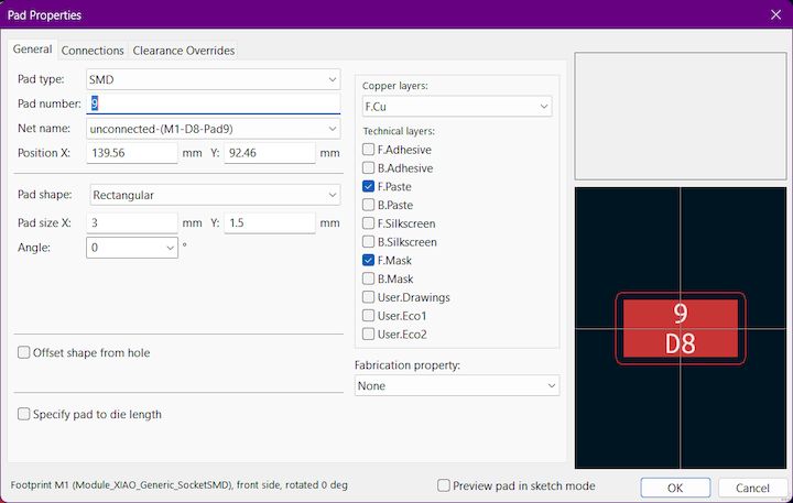
Step 2
So next we will change the Xiao - Seeed studio ESP32C3 pad size from X : 3mm to Y : 1.5mm. This will help us to place the Xiao Board accurate
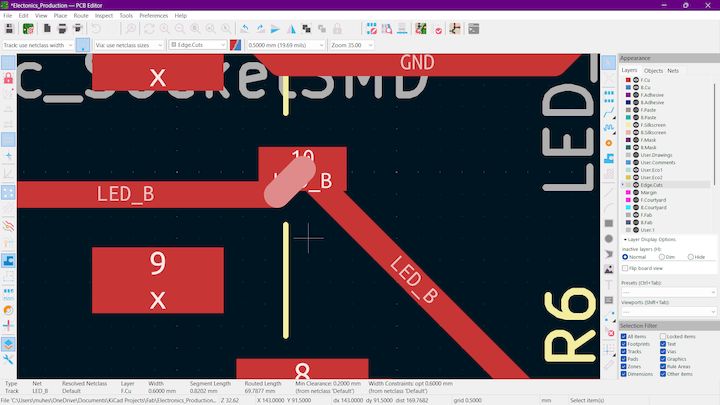
Step 3
And we have to check traces and It should not be connected like this
Step 4
Next we are gonna change the page to the actual bed size of our machine to print it accurately. Our bed size is within 100*100 mm. So we are gonna setup to that
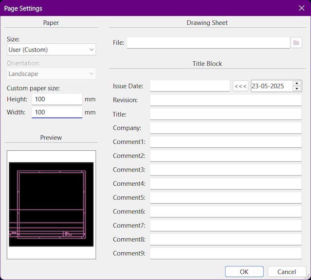
Step 5
Then fit the PCB inside like the below image
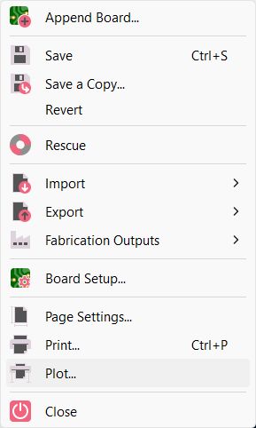
Step 6
Then we move to File -> Plot
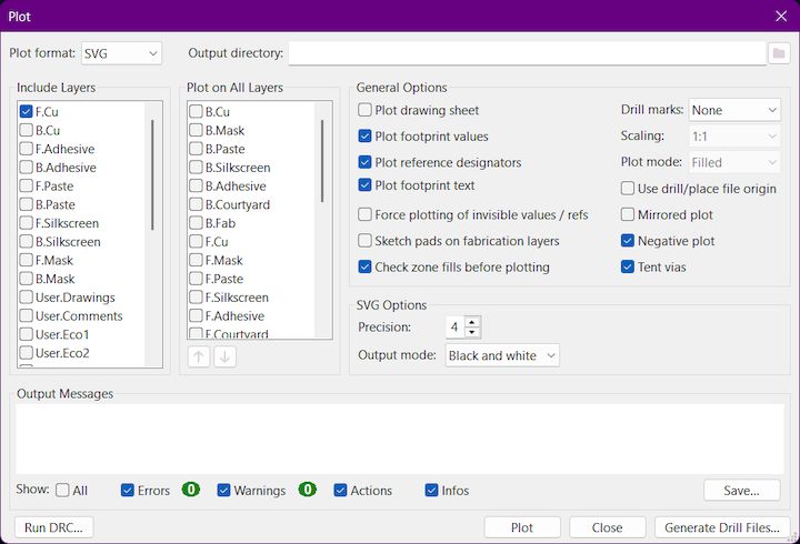
Step 7
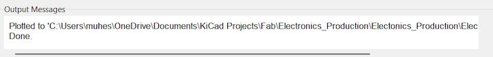
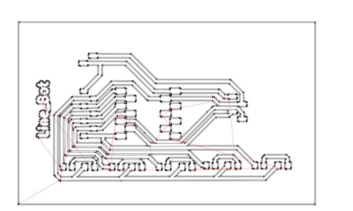
Next in the Plot Window, We have to select what are the layers that we are gonna print here we print F.Cu layer so we select that alone and then select the desired Output Directory and then Make sure to check the Negative Plot then only It will be easy for us to print the file in Wegster anthen output mode s black and white then select plot and then in output messages shown will be the directory and File name
This is the what we got as a Output
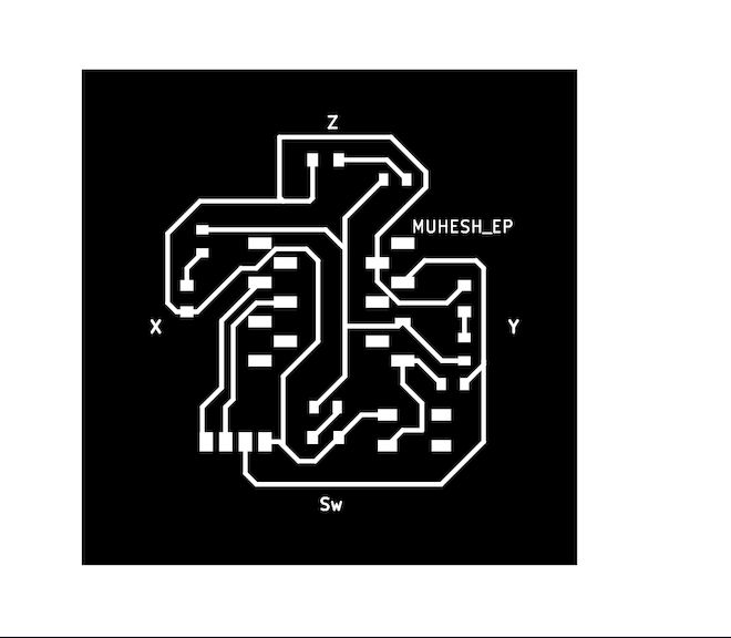
MODS CE Overview
MODS CE is a powerful web-based platform designed for controlling and interfacing with digital fabrication machines. It provides a modular interface for creating custom workflows that can be tailored to specific machines and processes.
With MODS CE, users can configure toolpaths, simulate processes, and manage machine settings all within a single, cohesive environment. It is particularly well-suited for educational settings and maker spaces, thanks to its flexibility and ease of use.
Advantages of MODS CE
- User-Friendly Interface: MODS CE offers an intuitive graphical interface that simplifies the process of machine configuration and control.
- Modular Design: The platform's modularity allows users to create custom workflows and adapt the system to a wide range of machines and tasks.
- Web-Based Access: Being web-based, MODS CE can be accessed from any device with a web browser, making it convenient and versatile.
- Educational Tool: It serves as an excellent educational resource, supporting hands-on learning and experimentation with digital fabrication technologies.
- Open Source: As an open-source platform, MODS CE encourages community contributions and continuous improvement.
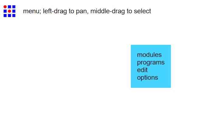
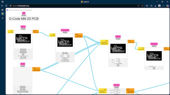
Then let’s move on to MoDSCE initally while get into this Interface I have reloaded my website that as it doesn't showed up anything
Then only read the Instructions to right click into get into options
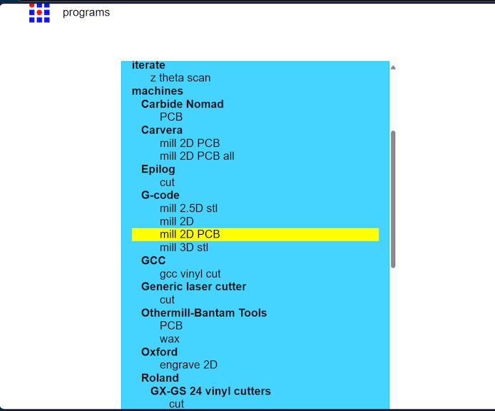
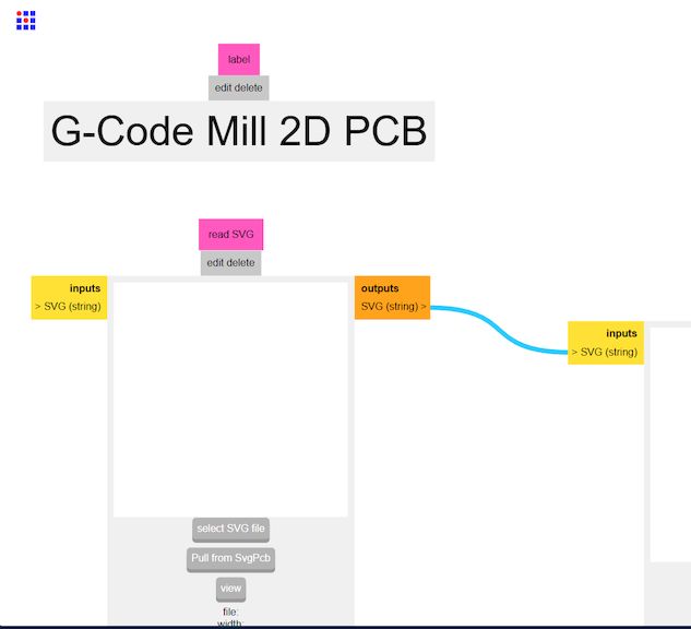
First we right click on the empty area and there will be a lot of pop ups from thee select the Programs
Then Click on the Mill 2D PCB and then Select the SVG file from your last week design
Then we move on to the offset selection for the board production as the board will be slightly deviate from actually see it om as a Design
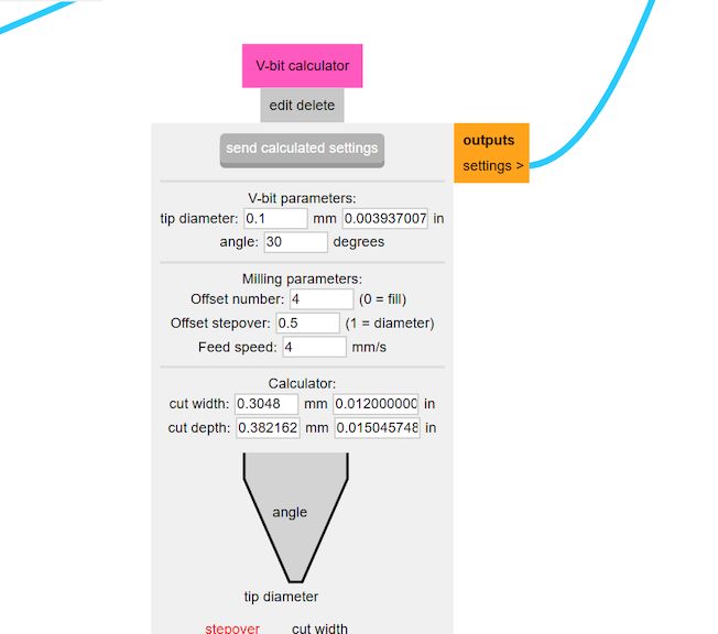
Then nwxt what we are gonna do is make some calculations and then provide a Proper result of how the things will be
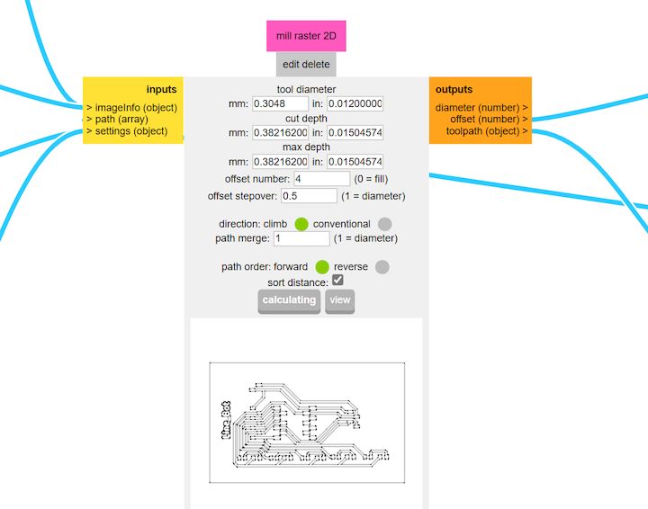
Then finally get a NC File in the output and save the output file that is the G-Code thats we need to be generated
PCB Milling
PCB milling involves mechanically removing material from a copper-clad board to create electrical isolation and form circuit patterns. Unlike traditional etching methods, which use chemical solutions to dissolve unwanted copper, milling uses precision-controlled milling bits to physically carve out the desired traces. The process is typically carried out using a Computer Numerical Control (CNC) milling machine, which is programmed to follow a specific design layout to guarantee accuracy and repeatability.
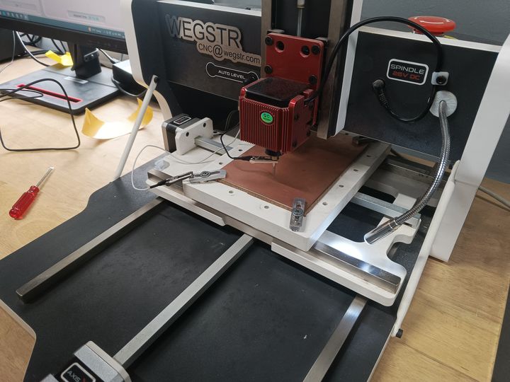
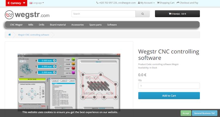
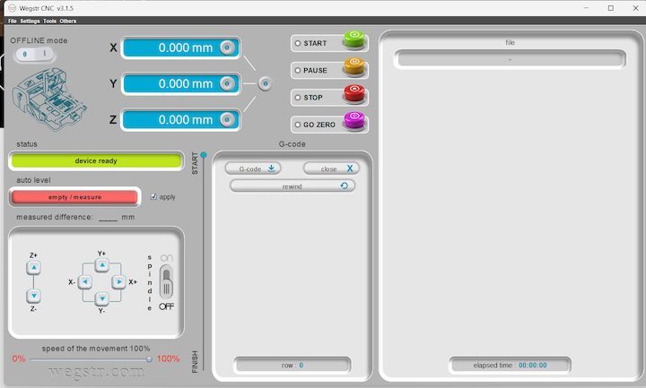
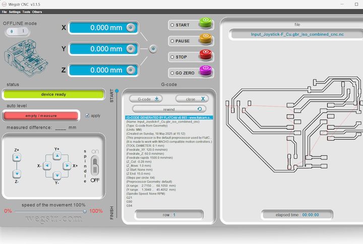
Introduction about Wegstr Machine and Software
The Wegstr PCB milling machine is a compact desktop CNC designed specifically for rapid PCB prototyping. It allows users to fabricate circuit boards by milling copper-clad boards instead of traditional chemical etching. This is ideal for makers, engineers, and students who want to quickly test their circuit designs. The Wegstr software complements the machine by providing an intuitive interface to load, simulate, and control the CNC toolpaths (usually in G-code format). Users can import files generated from FlatCAM (like the front copper and edge cuts), visualize the milling process, set spindle speeds, and control axis movements with precision. Together, the Wegstr machine and software offer a clean, fast, and eco-friendly approach to producing custom PCBs directly from your digital designs.
Our Machine Specification

Our Tool Bits
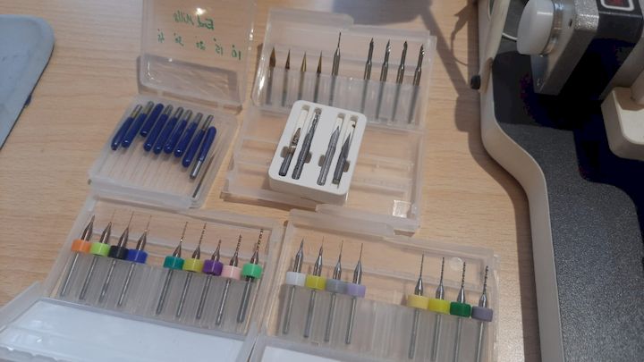
PCB Milling Bits – Introduction
PCB milling bits are precision cutting tools used in CNC milling machines to engrave, cut, and drill printed circuit boards (PCBs). These bits come in various shapes and sizes, each designed for specific operations like trace isolation, hole drilling, or edge cutting. Common types include engraving bits, V-bits, and end mills. Engraving Bits: Used for isolating copper traces. End Mills: Ideal for drilling and cutting board outlines. V-Bits: Provide sharp and clean traces for finer details. Material is usually tungsten carbide for durability. Bit selection depends on trace width, depth, board material, and required precision.
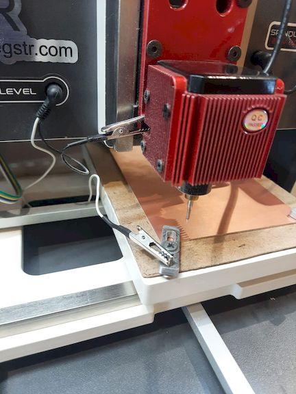
Auto Levelling
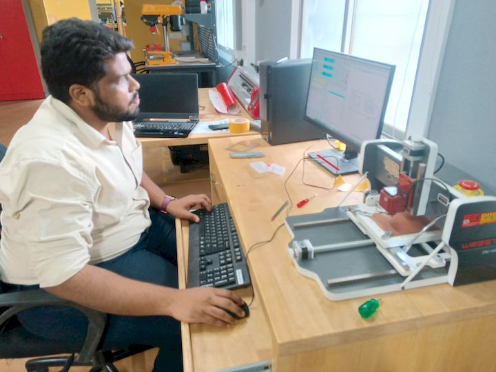
I connected the PCB milling machine to the PC and prepared it for fabrication. I securely fixed the copper-clad board onto the machine's bed using proper fixtures to ensure stability during milling. This alignment is crucial to prevent shifting, ensuring accurate cutting and precise trace isolation throughout the milling process.
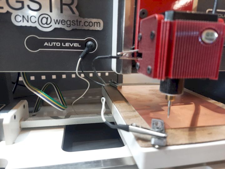
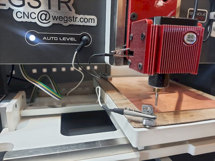
I manually verified the auto-leveling of the machine to ensure the milling bit would maintain accurate depth across the PCB surface. I carefully set the Z-axis zero position by gently lowering the bit until it just touched the copper surface, ensuring precise engraving during the PCB fabrication process.
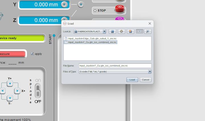
Then, I imported the F.Cu (front copper) file into the Wegstr software to verify auto-leveling across all test points. This step ensures the copper surface is uniformly leveled and aligned with the toolpath, preventing uneven milling and improving the accuracy and quality of the PCB engraving during fabrication.
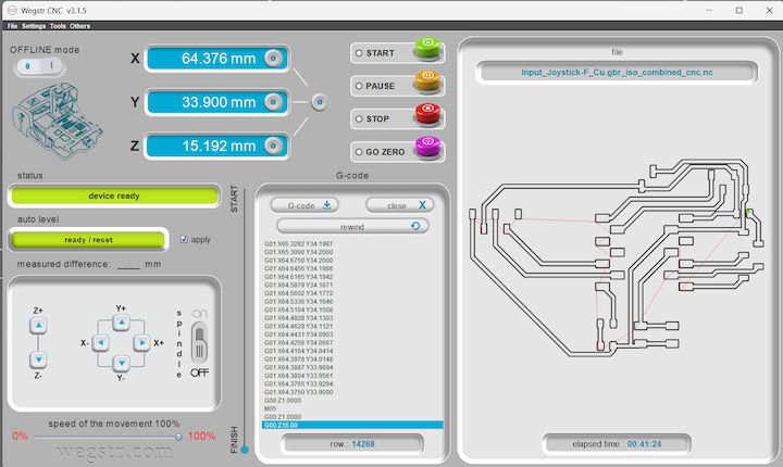
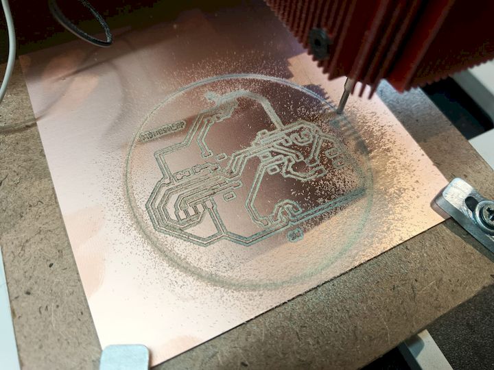
Milling Operation
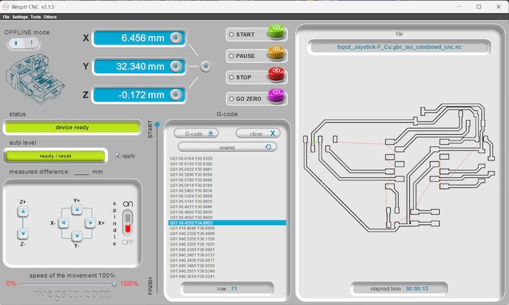
During the milling operation, the spindle rotated at 11,000 RPM while moving along the X and Y axes according to the generated NC code. The software automatically indicated completion once the milling process finished. The resulting PCB accurately reflected the generated toolpath and demonstrated successful fabrication.
Soldering & Assembly
After completing the PCB milling process, I prepared all the required components for assembly. Before soldering, I verified the component values and organized them according to the PCB layout to ensure a smooth assembly process.
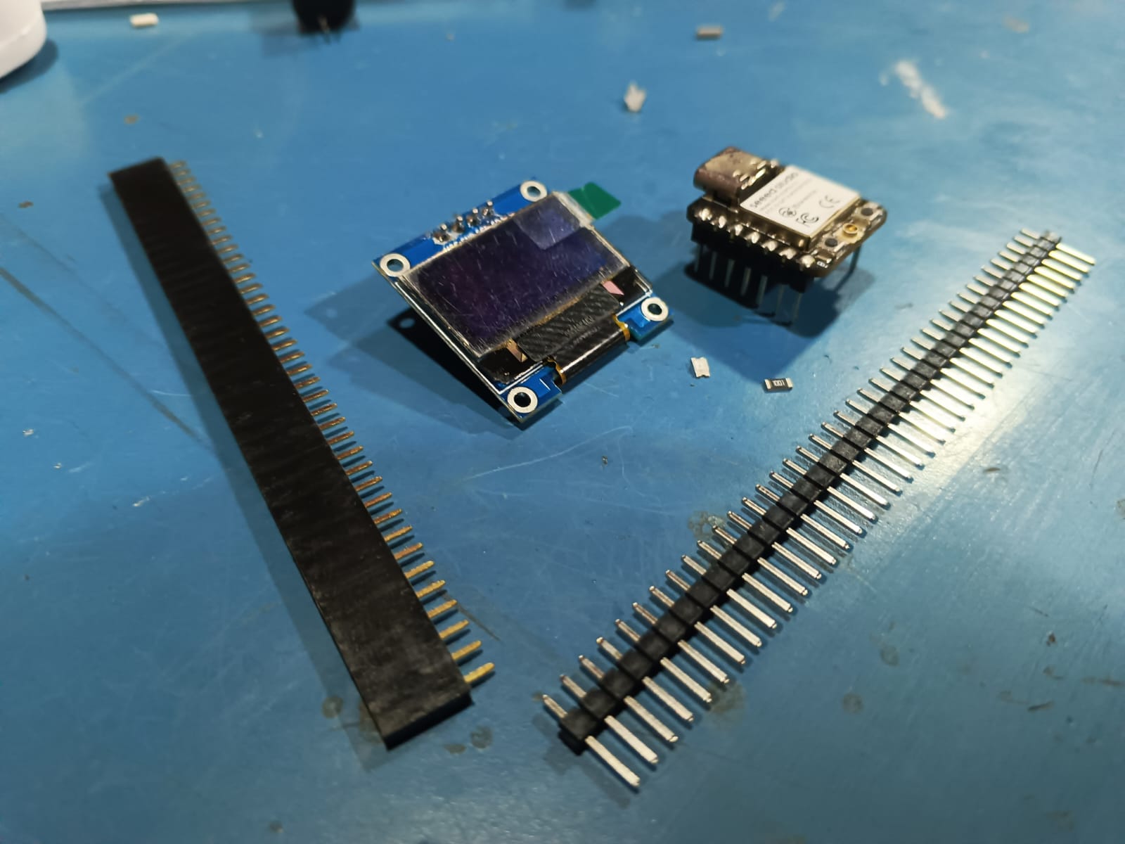
Electronic components used for assembly
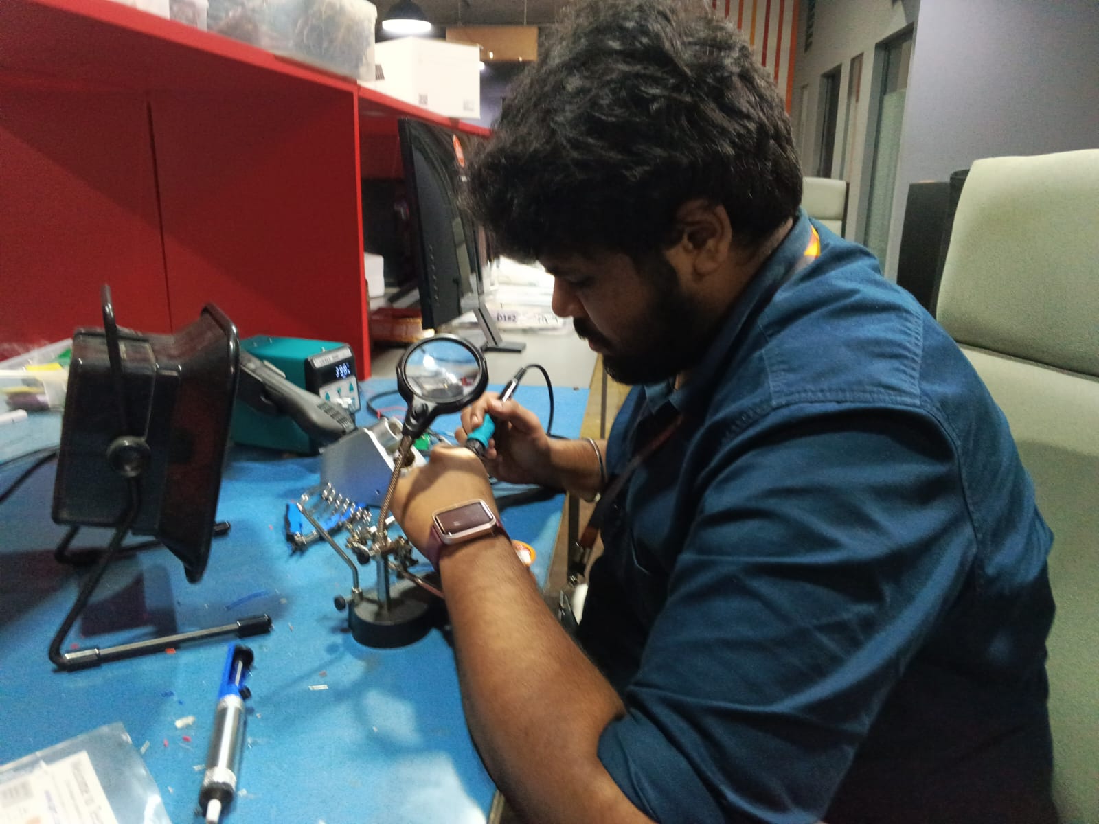
Soldering the fabricated PCB
Using a temperature-controlled soldering iron, I carefully soldered the components onto the fabricated PCB. Special attention was given to component orientation, solder joint quality, and proper placement of the XIAO ESP32-C3 module. Flux was used where necessary to improve solder flow and ensure reliable electrical connections.
After completing the assembly, the board was visually inspected for solder bridges, cold joints, and alignment issues. Once all connections were verified, the PCB was ready for testing and programming.
Board Testing and Validation
After completing the PCB fabrication and assembly process, the board was tested to verify the functionality of the XIAO ESP32-C3 microcontroller, OLED display, Wi-Fi connectivity, and output LED. A demonstration program was developed to display the current time, date, and day on the OLED screen using Network Time Protocol (NTP) synchronization.
The program automatically connects to a Wi-Fi network and obtains the current time from an NTP server. The OLED display cycles through three different screens:
- Time Display – Shows the current time in HH:MM:SS format.
- Date Display – Shows the current date in DD-MM-YYYY format.
- Day Display – Shows the current weekday.
Three indicator dots are displayed at the bottom of the OLED screen. The active dot highlights the currently displayed screen, providing a simple slide-show style user interface. The onboard LED was also used to confirm successful program execution and board functionality.
This test verified the following hardware and software functions:
- Power distribution and PCB connectivity.
- XIAO ESP32-C3 microcontroller operation.
- OLED display communication through I²C.
- Wi-Fi connectivity and internet access.
- NTP time synchronization.
- LED output operation.
Arduino IDE Test Program
The following Arduino IDE program was uploaded to the fabricated PCB to verify the functionality of the XIAO ESP32-C3 microcontroller, OLED display, Wi-Fi connectivity, and onboard LED. The program synchronizes time from an NTP server and displays the current time, date, and day on the OLED screen in a slideshow format.
                #include <WiFi.h>
                #include <Wire.h>
                #include <Adafruit_GFX.h>
                #include <Adafruit_SSD1306.h>
                #include <time.h>

                #define SCREEN_WIDTH 128
                #define SCREEN_HEIGHT 64

                Adafruit_SSD1306 display(SCREEN_WIDTH, SCREEN_HEIGHT, &Wire, -1);

                const char* ssid = "Muhesh";
                const char* password = "876543219";

                const int ledPin = D10;

                int currentScreen = 0;
                unsigned long lastSlideTime = 0;
                const int slideInterval = 3000;

                void connectToWiFi() {
                Serial.print("Connecting to WiFi");

                WiFi.begin(ssid, password);

                int retry = 0;

                while (WiFi.status() != WL_CONNECTED && retry < 40) {
                    delay(500);
                    Serial.print(".");
                    retry++;
                }

                if (WiFi.status() == WL_CONNECTED) {
                    Serial.println("\nWiFi Connected");
                    Serial.print("IP Address: ");
                    Serial.println(WiFi.localIP());

                    digitalWrite(ledPin, HIGH);
                } else {
                    Serial.println("\nWiFi Connection Failed");
                }
                }

                void setupTime() {
                configTime(19800, 0, "pool.ntp.org", "time.nist.gov");

                struct tm timeinfo;

                if (!getLocalTime(&timeinfo)) {
                    Serial.println("Failed to get time");
                } else {
                    Serial.println("Time synchronized");
                }
                }

                void setup() {

                Serial.begin(115200);

                pinMode(ledPin, OUTPUT);
                digitalWrite(ledPin, LOW);

                if (!display.begin(SSD1306_SWITCHCAPVCC, 0x3C)) {
                    Serial.println("OLED initialization failed");
                    while (true);
                }

                display.clearDisplay();
                display.display();

                connectToWiFi();
                setupTime();
                }

                String getTimeString() {

                struct tm timeinfo;

                if (!getLocalTime(&timeinfo))
                    return "No Time";

                char buffer[10];
                strftime(buffer, sizeof(buffer), "%H:%M:%S", &timeinfo);

                return String(buffer);
                }

                String getDateString() {

                struct tm timeinfo;

                if (!getLocalTime(&timeinfo))
                    return "No Date";

                char buffer[15];
                strftime(buffer, sizeof(buffer), "%d-%m-%Y", &timeinfo);

                return String(buffer);
                }

                String getDayString() {

                struct tm timeinfo;

                if (!getLocalTime(&timeinfo))
                    return "No Day";

                char buffer[15];
                strftime(buffer, sizeof(buffer), "%A", &timeinfo);

                return String(buffer);
                }

                void drawIndicators(int activeIndex) {

                int dotY = SCREEN_HEIGHT - 10;
                int startX = (SCREEN_WIDTH - (3 * 16)) / 2;

                for (int i = 0; i < 3; i++) {

                    if (i == activeIndex) {
                    display.fillCircle(startX + i * 16, dotY, 5, SSD1306_WHITE);
                    } else {
                    display.fillCircle(startX + i * 16, dotY, 2, SSD1306_WHITE);
                    }
                }
                }

                void loop() {

                unsigned long currentMillis = millis();

                if (currentMillis - lastSlideTime >= slideInterval) {

                    lastSlideTime = currentMillis;

                    String textToShow;

                    switch (currentScreen) {

                    case 0:
                        textToShow = getTimeString();
                        break;

                    case 1:
                        textToShow = getDateString();
                        break;

                    case 2:
                        textToShow = getDayString();
                        break;
                    }

                    display.clearDisplay();

                    display.setTextSize(2);
                    display.setTextColor(SSD1306_WHITE);

                    int yPos = (SCREEN_HEIGHT - 16) / 2;

                    display.setCursor(
                    (SCREEN_WIDTH - (textToShow.length() * 12)) / 2,
                    yPos
                    );

                    display.print(textToShow);

                    drawIndicators(currentScreen);

                    display.display();

                    currentScreen = (currentScreen + 1) % 3;
                }
                }
Hero Shot
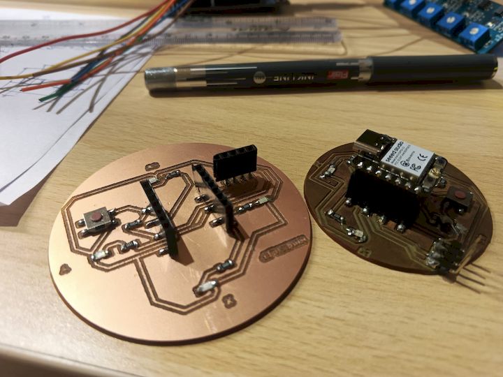
Initially, the first fabricated PCB developed a greenish surface layer. To improve the overall quality and reliability, I repeated the milling process and produced a second version, resulting in a cleaner and more accurate final board.
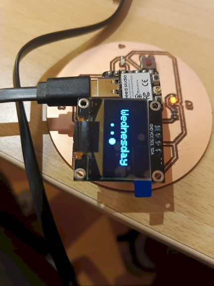
And the Board is working Properly
Learning Summary
This week helped me understand the complete PCB production workflow, from designing a circuit in KiCad to fabricating a functional PCB using the Wegstr CNC milling machine.
I learned how to modify design rules, adjust track widths and pad sizes, generate plot files, and prepare manufacturing-ready outputs. Through MODS CE, I gained experience in generating toolpaths and NC files required for PCB milling.
During fabrication, I learned machine setup, auto-levelling, tool selection, and the importance of accurate Z-axis calibration. I also understood how milling parameters affect trace quality and overall board reliability.
Overall, this assignment improved my skills in PCB design, CNC-based PCB manufacturing, troubleshooting fabrication issues, and producing a working electronic board from a digital design.
Finally Leaving my files here
Tip: Before sending to a manufacturer, use a Gerber Viewer to check your files.
Navigate Here
- Objectives of the Week
- Group Assignment Contribution
- Wegstr CNC Overview
- PCB Toolpath Preparation
- KiCad Adjustments
- MODS CE Workflow
- PCB Milling
- Wegstr Machine & Software
- Machine Specifications
- PCB Milling Bits
- Auto Levelling
- Milling Operation
- Soldering & Assembly
- Board Testing & Validation
- Hero Shot
- Learning Summary
- Design Files