- Week 1 : Project Management
- Week 2 : Computer-aided
- Week 3 : Computer Controlled Cutting
- Week 4 : Embedded Programming
- Week 5 :3D Scanning and Printing
- Week 6 : Electronic Design
- Week 7 : Computer Controlled Machining
- Week 8 : Electronics Production
- Week 9 : Input Devices
- Week 10 : Output Devices
- Week 11 : Networking and Communication
- Week 12 : Mechanical Design and Machine Design
- Week 14 : Molding and Casting
- Week 15 : Interface and Application Programming
- Week 16 : System Integeration
- Week 17 : Wildcard Week
- Week 18 : Applications and Implications, Project Development
- Week 19 : Invention, Intellectual property and Income
- Week 20 : FInal Project Requirements
Week 7: Computer Controlled Machining
Objectives of the Week
Group Assignment
Individual Assignment
Group Assignment Contribution
To Know More About How I make this....
In this Week, I have Contributed in doing the CAM toolpath for my CNC Machine for making different type of Joints to my Wood Fabricated things
Common Wood Joints
1. Butt Joint
The butt joint is the simplest type of wood joint where two pieces of wood are joined by simply butting them together. They are usually glued, nailed, or screwed, and are often reinforced for strength.
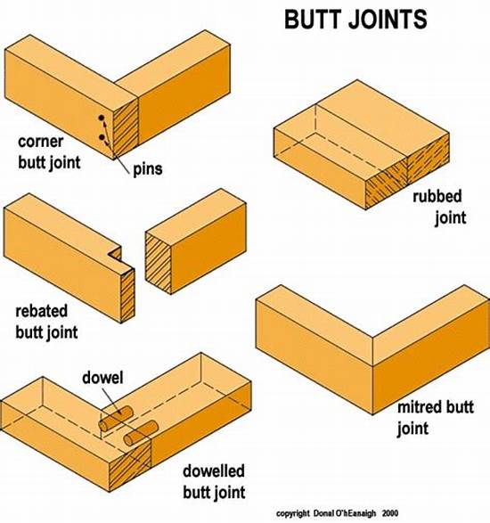
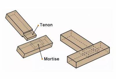
2. Mortise and Tenon Joint
This is a strong and traditional joint where a projecting tenon fits into a matching mortise (hole) cut into the other piece. It’s commonly used in furniture for its durability and precise fit.
3. Dovetail Joint (Main Focus)
The dovetail joint is known for its strength, resistance to pulling apart, and aesthetic appeal. It is often used in drawers, boxes, and fine woodworking.
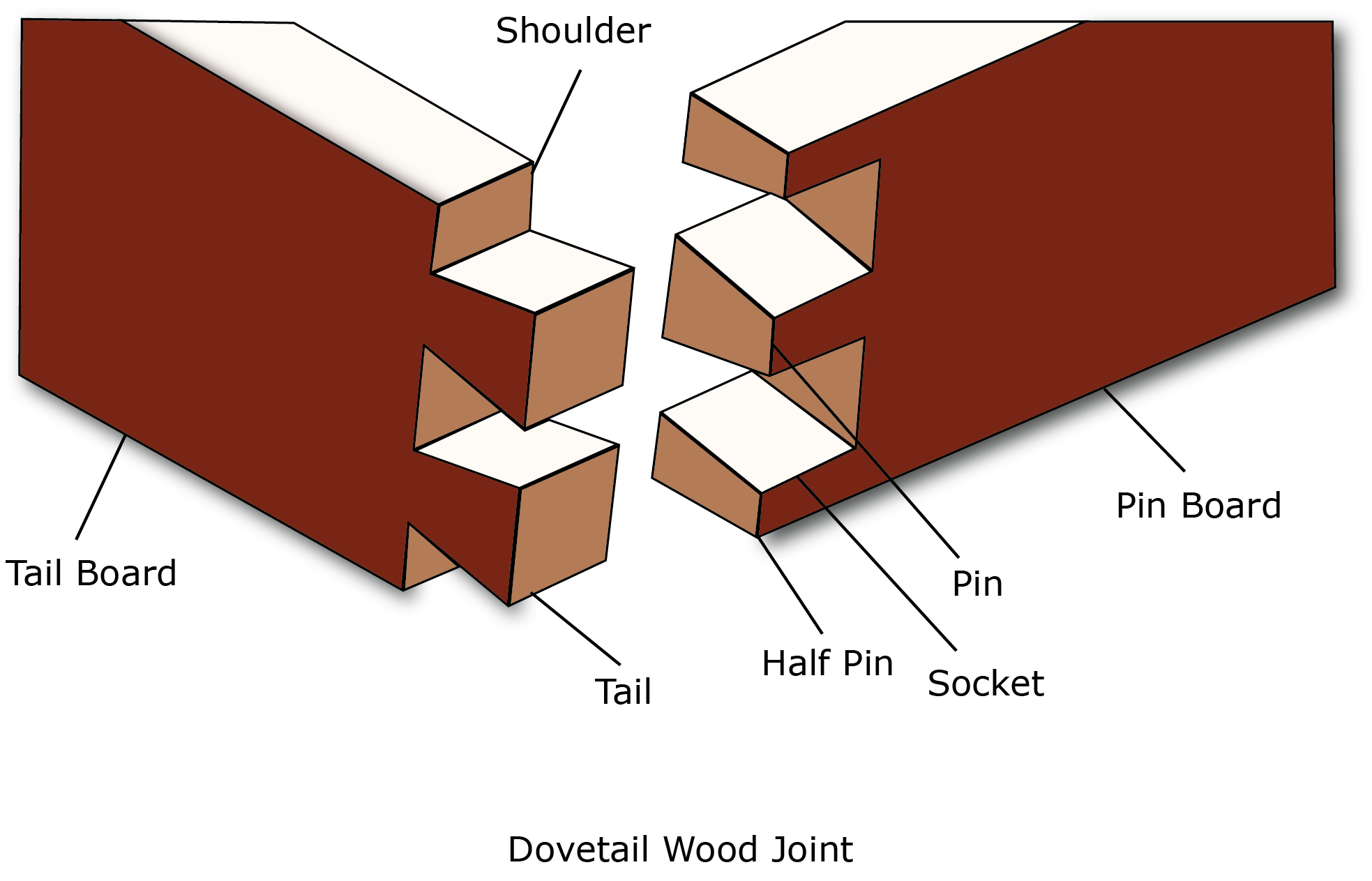
Key Features of Dovetail Joints:
- Consists of interlocking "tails" and "pins" cut at angles.
- Creates a mechanical lock without needing nails or screws.
- Excellent resistance to tension (pulling apart).
- Often used in visible joints because of its decorative look.
- Requires skill and precision to cut, traditionally done by hand or with a jig.
Types of Dovetail Joints:
- Through Dovetail: Both ends of the joint are visible.
- Half-Blind Dovetail: Only one side shows the joint, common in drawer fronts.
- Secret Mitered Dovetail: Hidden from all sides, used for elegant boxes.
Advantages of Dovetail Joints:
- Strong and durable without hardware.
- Resistant to wear and tear over time.
- Enhances the craftsmanship and value of woodwork.
In summary, while there are many ways to join wood, the dovetail joint stands out as a hallmark of traditional woodworking mastery due to its strength, longevity, and beautiful appearance.
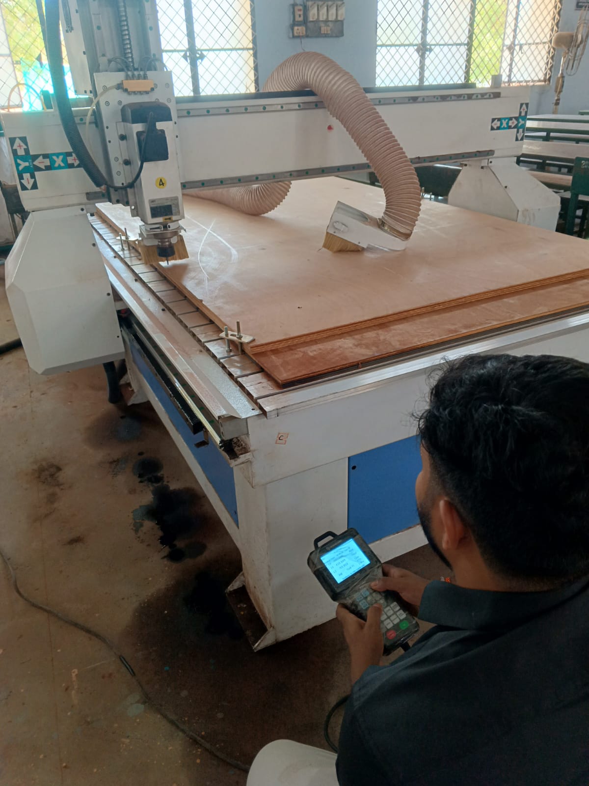
CNC Wood Router
A CNC (Computer Numerical Control) Wood Router is a computer-controlled machining system used for cutting, drilling, engraving, and shaping wooden materials with high precision. Unlike conventional woodworking tools, CNC routers follow programmed toolpaths generated from CAD/CAM software, enabling accurate and repeatable manufacturing of complex parts.
CNC routers are widely used in furniture manufacturing, interior design, signage production, cabinet making, and digital fabrication laboratories. They are capable of machining materials such as plywood, MDF, acrylic, composites, and certain non-ferrous materials.
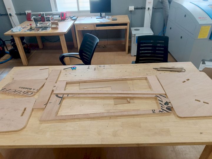
For this assignment, a large-format CNC wood router was used to manufacture the components of the BYTES Table from plywood sheets. The machine enabled precise cutting of press-fit joints and large structural components that would be difficult to produce manually.
Working Principle
The CNC router operates by converting digital designs into machine movements. The workflow begins with creating a 2D or 3D model using CAD software. The design is then processed in CAM software to generate toolpaths and G-code instructions.
The machine controller interprets the G-code and moves the spindle along the X, Y, and Z axes. The rotating cutting tool removes material according to the programmed toolpath, producing the desired shape with high accuracy.
- CAD Design Creation
- CAM Toolpath Generation
- G-Code Export
- Material Setup and Clamping
- Machine Homing and Zero Setting
- Automated Machining Operation
- Part Removal and Finishing
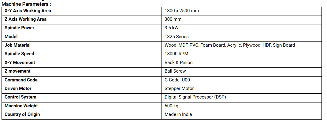
Machine Specifications
| Specification | Value |
|---|---|
| Machine Type | 3-Axis CNC Wood Router |
| Working Axes | X, Y and Z |
| Machine Bed | T-Slot Aluminium Bed |
| Control Method | CNC Controller with Handheld Pendant |
| Dust Collection | Integrated Dust Extraction System |
| Workpiece Material | Plywood, MDF, Acrylic and Wood |
| Spindle Type | High-Speed Router Spindle |
| Cooling Method | Air Cooled |
| Programming Input | G-Code |
| Tool Holding | ER Collet System |
Why CNC Routing?
The BYTES Table contains large structural components and multiple press-fit joints that require precise dimensions. CNC routing provided high accuracy, repeatability, and efficient material utilization while significantly reducing manual fabrication time. The machine was able to produce all parts directly from a single plywood sheet with minimal post-processing.
- High dimensional accuracy
- Fast manufacturing process
- Repeatable results
- Excellent edge quality
- Suitable for large plywood sheets
- Efficient material utilization
Individual Assignment
Now Let's jump into the Individual Assignment
Design a BYTES Table
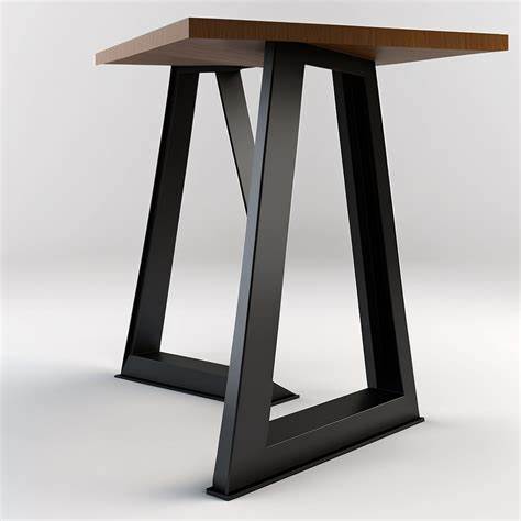
I just got much more thinking, How we will work while having a sip of coffee or have a nice dehyradation time. So I want myself to design something that can be used while working on laptops while having quick bytes
Concept to Design
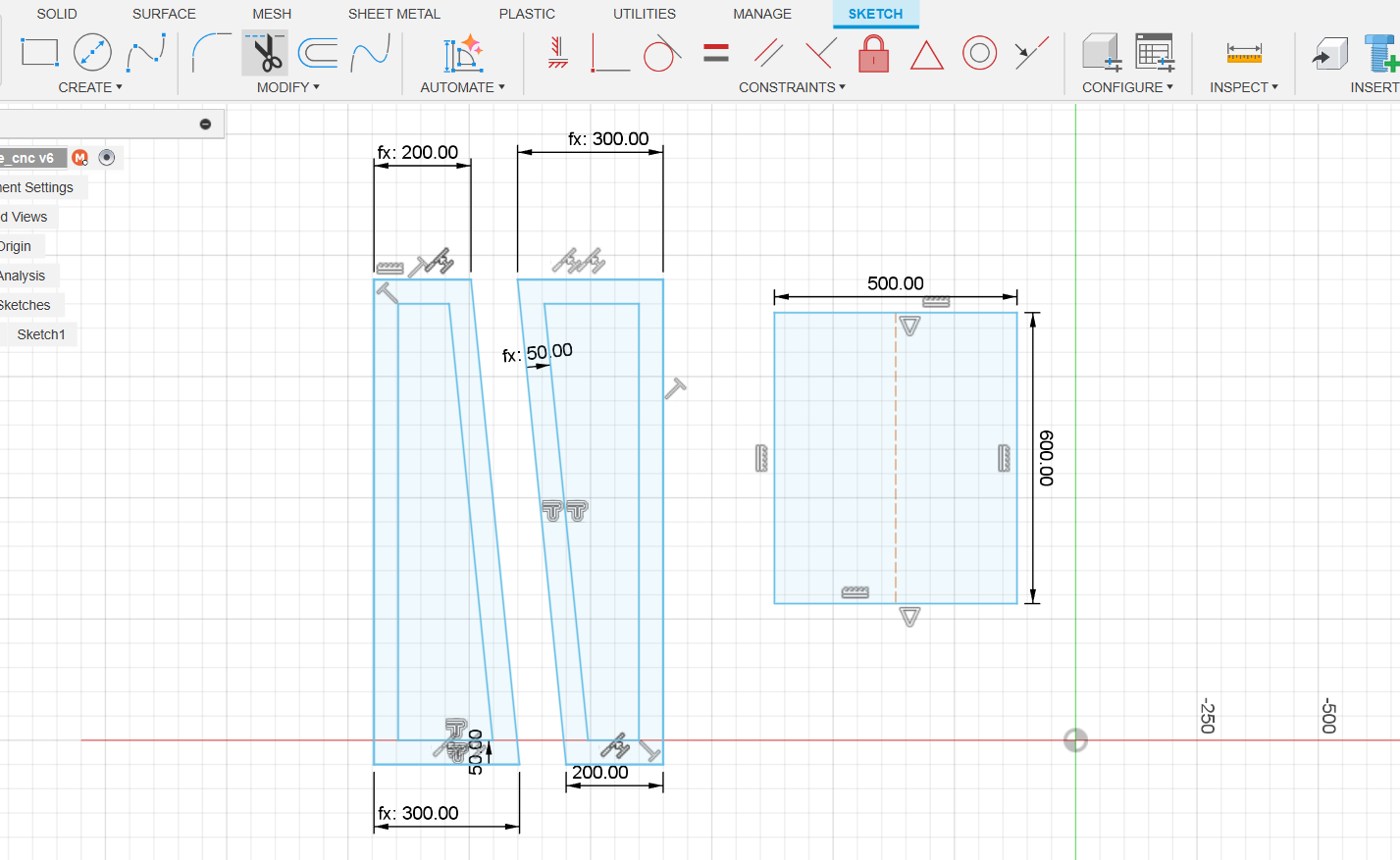
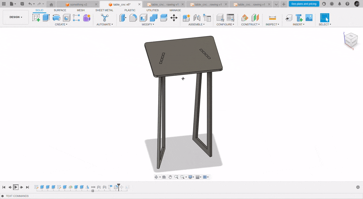
I have used the Fusion 360 Software to design this thing
- Its just a simple thing nothing much complicates in design
- Initially got an experienve in 3D Design Week
- And then I just Take imaginary measurements and some measurements according to my laptop and my working space
- And then we have considered our Plywood things 8*4 Inch with 18mm thickness
Artcam Software
ArtCAM is a software for designing and manufacturing 2D and 3D models. It is a powerful tool for creating complex designs and models with ease. It is used by designers, engineers, and manufacturers to create detailed designs and models quickly and easily.
ArtCAM can be used to create 2D and 3D models from scratch, as well as to modify existing designs. It has a wide range of tools and features that make it easy to create complex designs and models. It also has a powerful rendering engine that allows users to see their designs in high-quality 3D.
Download Artcam Software
To download the Artcam software, click here.
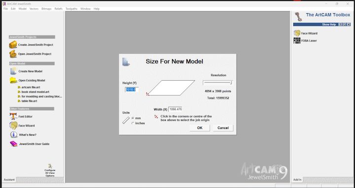
In this step, I set up the material size in millimeters (mm) for my model in ArtCAM Jewelsmith 9.1. I carefully defined the width, height, and thickness of the material to ensure the design fits accurately within the working area, enabling precise cutting and alignment during fabrication.
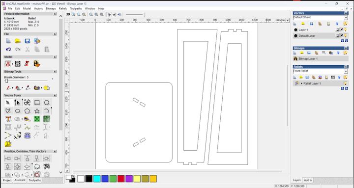
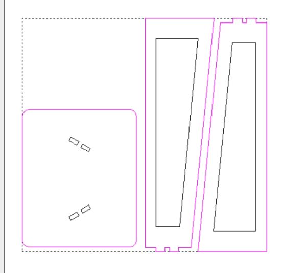
In the Vector option of ArtCAM Jewelsmith 9.1, I clicked on “Load Vector” to import my DXF file. This allowed me to bring in the design I created earlier and prepare it for toolpath creation and further operations like engraving or cutting.
Importing Files in Artcam
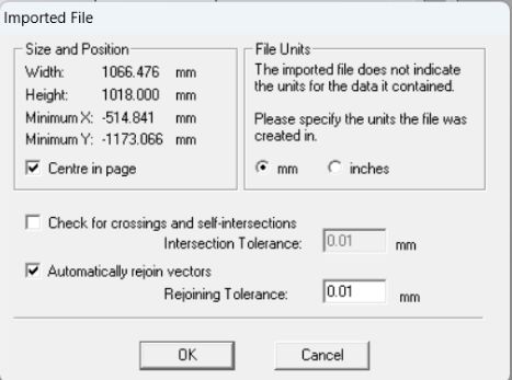
Imported File
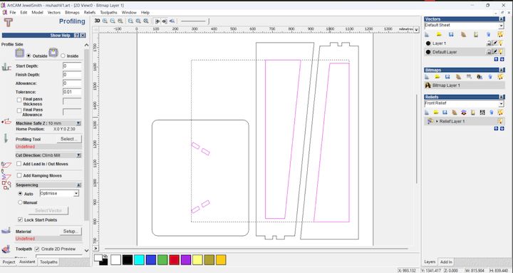
Tool Path for Internal Cutting
I aligned it properly within the material workspace to ensure accurate machining. Proper alignment ensures the design fits within the set material boundaries and is positioned correctly for toolpath generation and cutting operations.
Material Cut area selection
Tool bit Selection
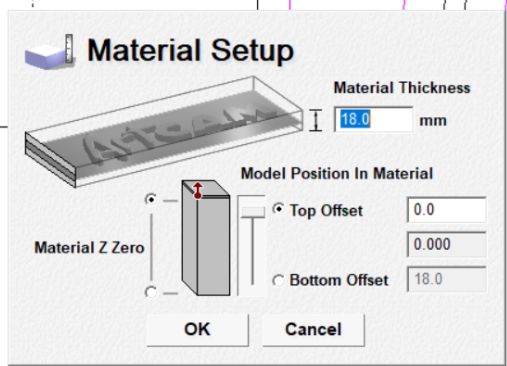
Based on the material thickness, I set the finish depth to 18 mm to ensure complete cutting through the stock. This depth setting aligns with the actual material size, allowing precise machining without leaving any excess material at the base.
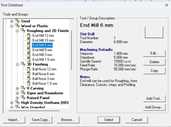
In this step, I selected the tool bit that I wanted to use for cutting and its come around 6mm ball mill cutting tool
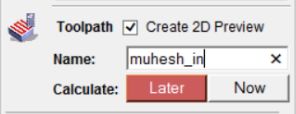
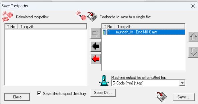
Saving the Tool Path
And I am Going to save the tool path that we have previously developed for working on and going to name it as "muhesh_in"
External Tool Path Cutting
Now we are gonna repeat the same process that we were using for the internal tool path and create the External tool path
Machining Process
Now Let's see How machining process were done for the Design developed
The below mentioned image is the Specifications of our Woood Routing CNC Machine
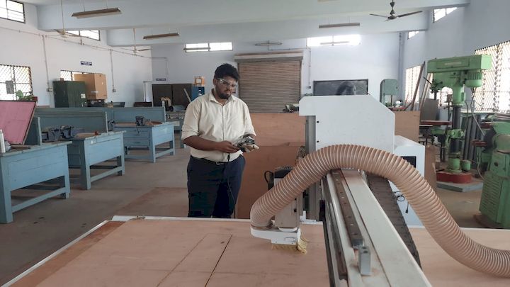
Initial Setup
Before getting into the actual works, Initially we need to setup the machine like checking the tools and setting the spindle speed
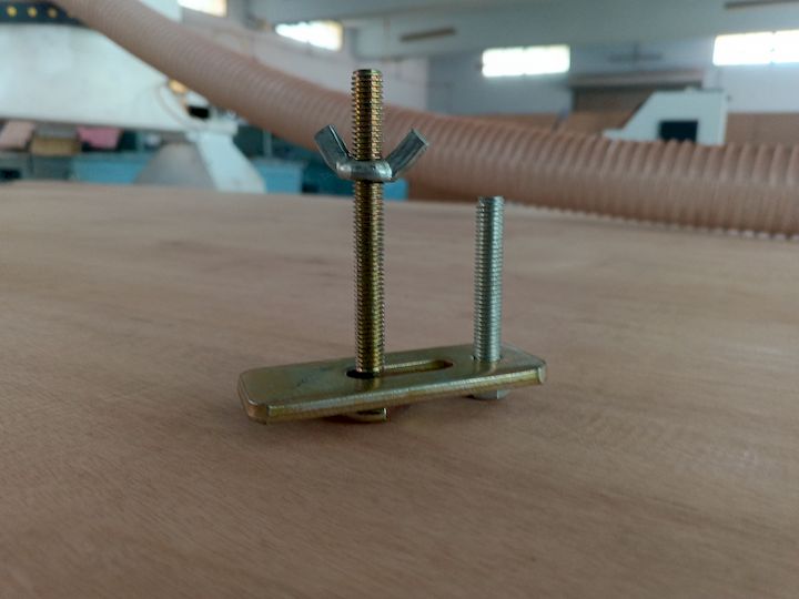
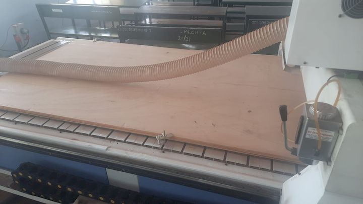
Now what are gonna do is clamp the material with the bed using the clamps and then having the material ready for the machining
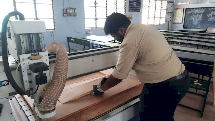
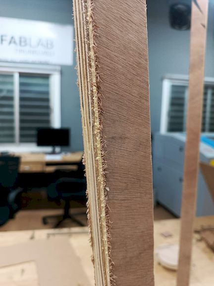
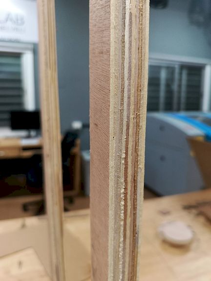
I secured the 18mm plywood using appropriate fixtures to ensure it remained stable during the machining process. This helped prevent any movement or vibration, allowing for accurate and precise cuts. Proper fixturing is essential for maintaining alignment and achieving consistent results in fabrication.
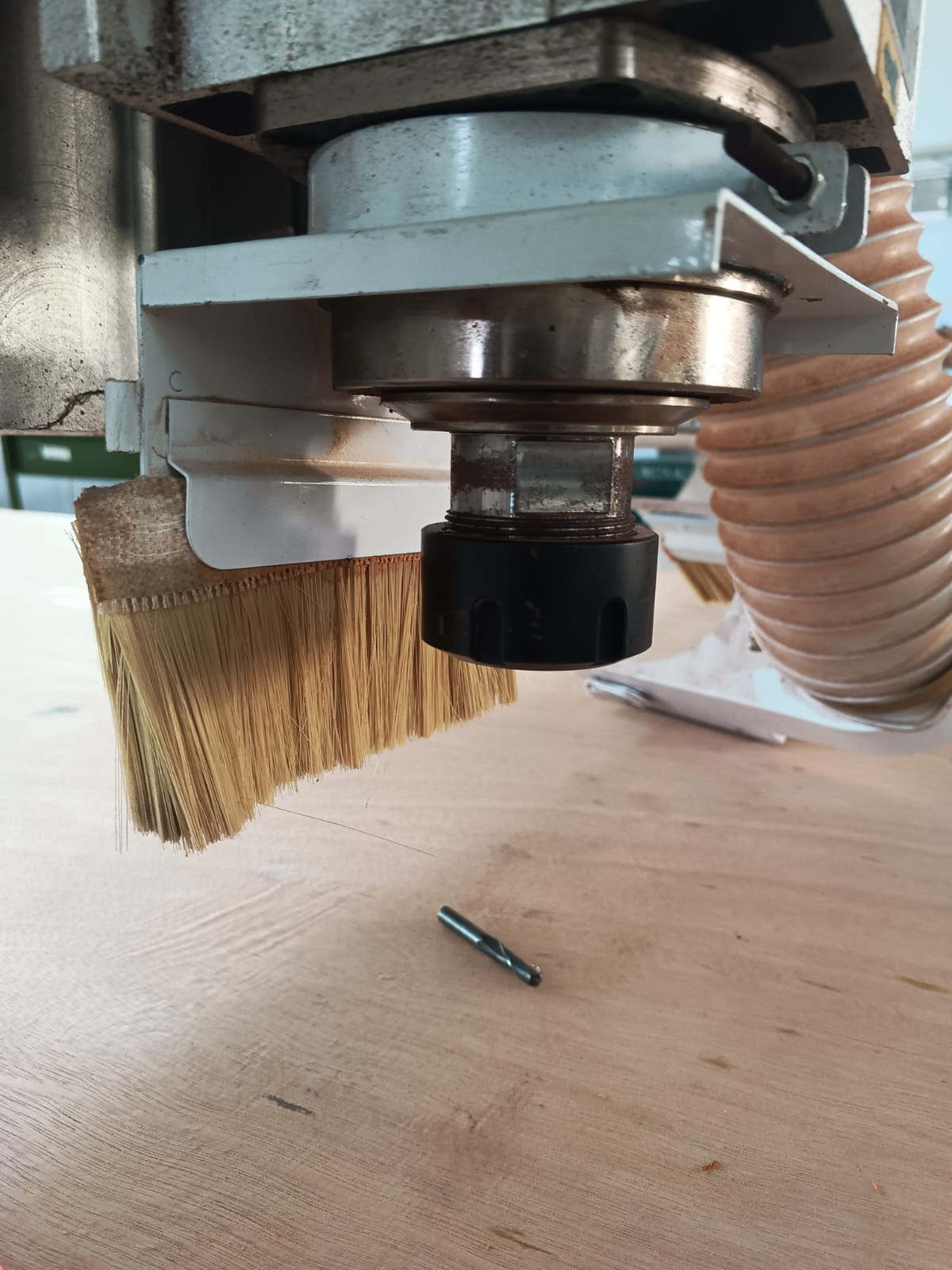
Milling Tools Used
For machining the BYTES table, a flat end mill was used to perform both the pocketing and profile cutting operations. The tool was selected based on the material thickness, cutting requirements, and machine capabilities.
| Parameter | Value |
|---|---|
| Tool Type | Flat End Mill |
| Diameter | 6 mm |
| Flutes | 2 |
| Operation | Profile Cutting |
The 6 mm flat end mill provided sufficient rigidity for machining plywood while maintaining good cutting quality and dimensional accuracy. The same tool was used throughout the machining process to create the internal slots and external profiles required for the press-fit assembly.
Using the teach pendant, I controlled the CNC wood routing machine to accurately set the origin point. This step ensures that the machine starts cutting from the correct reference position, allowing for precise alignment of the toolpath with the material. Proper origin setting is critical for accurate machining.
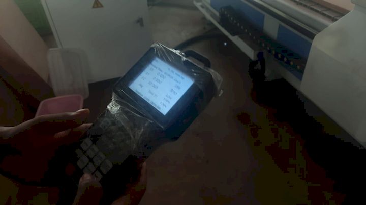
To set up the tool at the proper origin, I verified the alignment by checking the X, Y, and Z coordinates manually. I ensured the tool touched the surface accurately without damaging the material. This verification step is essential to maintain cutting precision and avoid any misalignment during machining.
After transferring the file to the CNC machine using a pen drive, I loaded the program and initiated the run. I closely monitored the initial steps to ensure proper execution, verifying that the toolpath aligned with the material setup to achieve accurate cutting results without any errors.
Inside Cut Operation
After generating and verifying the toolpath, I started the inside cut operation. During this process, the CNC router followed the predefined internal contours and slots within the design. I continuously monitored the machine to ensure the cutting depth, feed rate, and tool alignment remained accurate throughout the machining process. Proper supervision helped prevent tool deflection and ensured that all internal features were machined precisely according to the design specifications.
Outside Cut Operation
Once the internal features were completed, I proceeded with the outside cut operation. This final machining step followed the external profile of each component, separating the finished parts from the plywood sheet. Care was taken to maintain the correct work origin and machining parameters to achieve clean edges and dimensional accuracy. Tabs were retained during cutting to prevent the parts from shifting until the machining process was fully completed.
Post Processing
After machining was completed, all the components were carefully removed from the plywood sheet by cutting the holding tabs and separating the individual parts. The edges were then cleaned using sandpaper to remove burrs and machining marks. This post-processing step ensured proper fitting of joints and improved the overall surface finish of the final product.
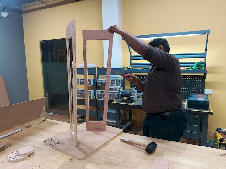
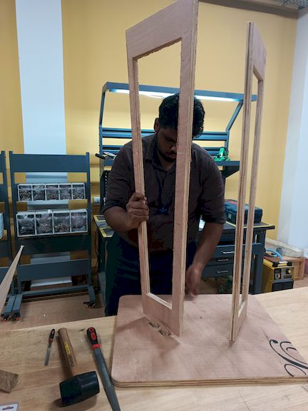
Assembly
After completing the post-processing operations, all the machined components were assembled according to the design. The press-fit joints were aligned carefully and fitted together to form the final structure. Minor adjustments were made where necessary to achieve a stable and rigid assembly.
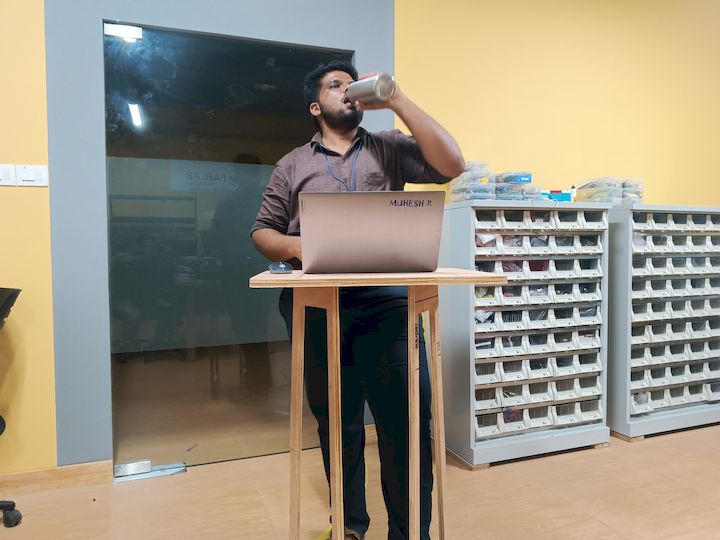
Hero Shot
The final assembled BYTES Table fabricated using CNC machining.

Learning Summary
This week provided me with practical experience in large-format CNC machining and digital fabrication workflows. I learned how to transform a CAD model into a manufacturable product by creating toolpaths, selecting machining parameters, and preparing material for CNC operations.Through the group assignment, I gained knowledge about different woodworking joints such as butt joints, mortise and tenon joints, and dovetail joints. Understanding these joints helped me appreciate how mechanical strength and assembly methods influence furniture and structural design.
During the individual assignment, I designed and fabricated the BYTES Table using Fusion 360 and ArtCAM. This process improved my skills in 2D and 3D design, DXF export, toolpath generation, material setup, and CNC machining workflows.
I learned the importance of selecting appropriate feeds, speeds, cutting depths, and tooling parameters. Small mistakes in toolpath generation or material alignment can significantly affect the final result, making machine setup and verification critical steps before machining.
This week also strengthened my understanding of press-fit construction techniques and how tolerance affects assembly quality. Testing and refining joints allowed me to achieve a stable structure without relying heavily on additional fasteners.
Overall, this assignment helped me develop confidence in operating CNC machinery, planning manufacturing processes, and producing large-scale functional objects from sheet materials using digital fabrication techniques.
Download Files
The complete project files, including the original design files, CAM toolpath files, and the combined project archive, are provided below for reference and future use.