Week 7 : Computer Controlled Machining
Objectives of the Week
- Complete your lab’s safety training
- Test runout, alignment, fixturing, speeds, feeds, materials and toolpaths for your machine
- Document your work to the group work page and reflect on your individual page what you learned
CNC Wood Router Overview
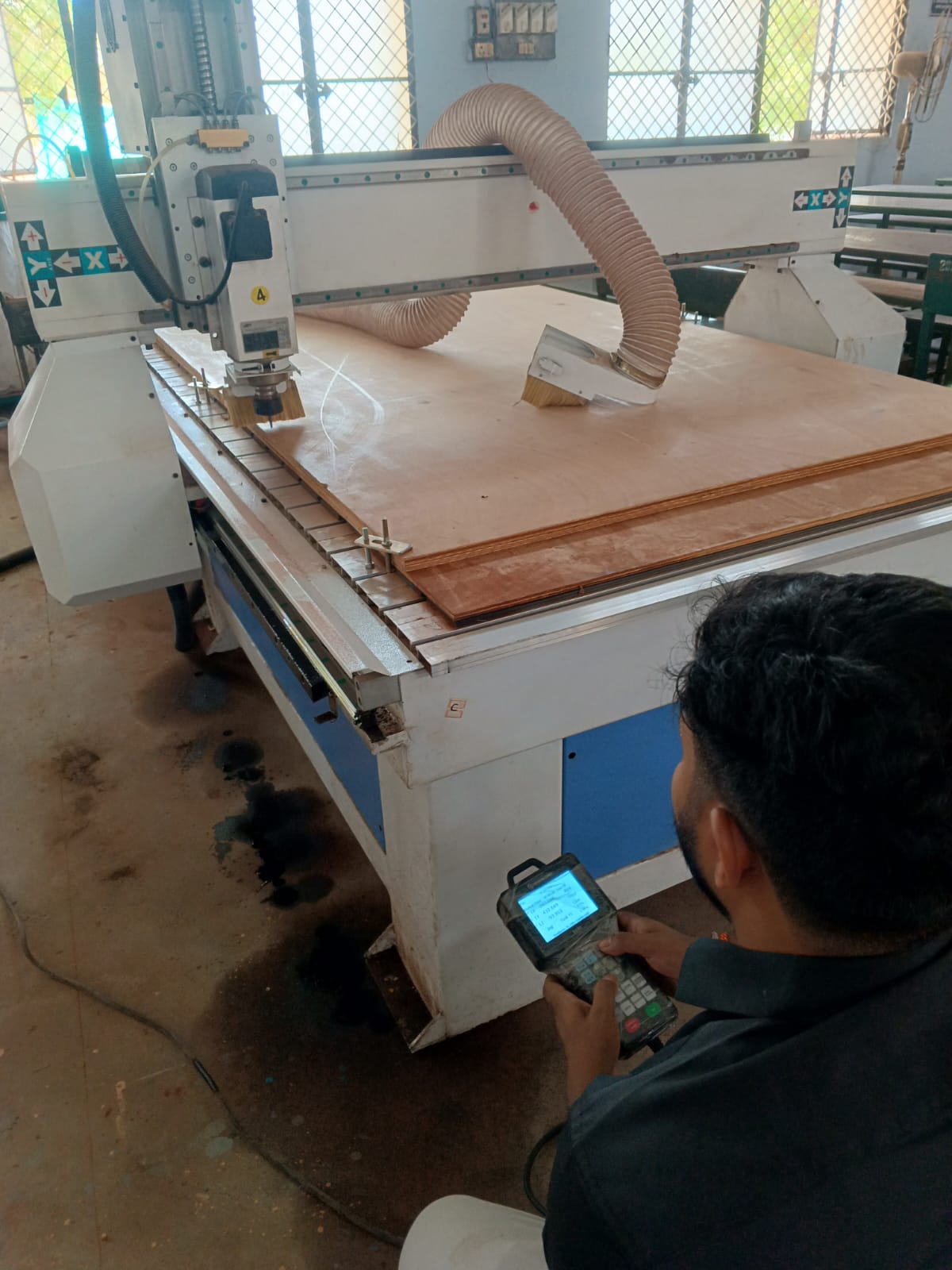
For this week's group assignment, we characterized the CNC Wood Router available in our lab. The objective was to understand machine behaviour by evaluating alignment, workholding methods, spindle operation, feeds and speeds, tooling, and machining quality. The machine was tested using plywood material and various cutting parameters to determine suitable operating conditions.
The CNC router is capable of performing profile cutting, pocketing, drilling, engraving, and 2.5D machining operations on wood-based materials. Proper machine setup and parameter selection are essential to achieve dimensional accuracy and surface quality.
Why Use a CNC Milling Machine?
Traditional machining and woodworking machines often require significant manual operation, skill, and setup time to achieve accurate results. In contrast, a CNC (Computer Numerical Control) machine automates the machining process using computer-generated toolpaths, enabling precise, repeatable, and efficient manufacturing.
CNC machines can process a wide range of materials including wood, plywood, MDF, acrylic, engineering plastics, foam, composites, and, with sufficiently rigid machines and appropriate tooling, even metals such as aluminium. This flexibility makes CNC machining one of the most widely used digital fabrication technologies for prototyping and production.
| Advantages | Disadvantages |
|---|---|
| High precision and repeatability | High initial machine investment cost |
| Increased productivity and faster manufacturing | Requires knowledge of CAD, CAM, and machine operation |
| Capable of producing complex and intricate designs | Regular maintenance of cutting tools and machine components |
| Efficient material utilization with minimal waste | Generates wood dust and noise, requiring proper dust extraction systems |
| Seamless integration with CAD/CAM software workflows | Generally limited to flat-sheet and shallow 3D machining operations |
Due to these advantages, CNC milling machines have become an essential tool in modern digital fabrication environments, enabling rapid prototyping, accurate manufacturing, and efficient production workflows.
Machine Specifications
| Parameter | Specification |
|---|---|
| Machine Type | CNC Wood Router |
| Axis Configuration | 3-Axis (X, Y, Z) |
| Control System | DSP / Mach3 Controller |
| Spindle Type | High Speed Router Spindle |
| Materials Tested | Plywood, MDF |
| Operations | Profile, Pocket, Drilling |
Common CNC Cutting Tools
Various cutting tools are used in CNC wood routing depending on the machining operation and desired surface finish. Selecting the correct tool improves machining quality, dimensional accuracy, cutting efficiency, and tool life. Each tool is designed for a specific purpose such as profiling, pocketing, engraving, drilling, surfacing, or 3D carving.
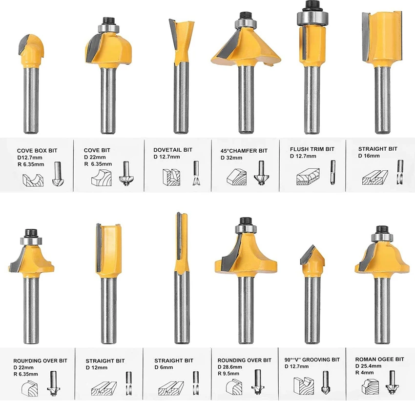
Figure: Common cutting tools used in CNC woodworking applications.
- End Mill (Straight Cutter): Used for profile cutting, pocketing, and contour machining with flat-bottomed results.
- Ball Nose Bit: Suitable for 3D contouring and curved surfaces, producing smooth rounded finishes.
- V-Bit (Engraving Bit): Used for engraving, lettering, chamfering, and decorative carvings.
- Upcut Bit: Pulls chips upward for efficient chip removal and deep cutting operations.
- Downcut Bit: Pushes chips downward, providing cleaner top surface finishes and reduced tear-out.
- Compression Bit: Combines upcut and downcut flutes to achieve clean top and bottom edges, especially in plywood.
- Fly Cutter (Surfacing Bit): Used for flattening spoilboards and surfacing large wooden panels.
- Tapered Ball Nose Bit: Ideal for detailed 3D carving with increased rigidity and reduced tool deflection.
- Dovetail Bit: Designed for creating dovetail joints and angled slots used in woodworking joinery.
- Drill Bit: Used for producing vertical holes for dowels, fasteners, and hardware installation.
Machine Operation Checklist

To ensure safe and efficient CNC machining, a systematic inspection was performed before, during, and after every machining operation. This checklist helped verify machine readiness, material stability, operator safety, and overall machining quality.
Before Starting the Machine
- Machine: Verify that the cutting tool is in good condition and securely mounted. Ensure there are no obstacles around the machine and that the machine bed is clean and free from dust or debris.
- Material: Confirm that the selected material is suitable for machining and securely fixed to the machine bed using appropriate clamping methods to prevent movement during cutting.
- Movement: Check the movement of all machine axes (X, Y, and Z) to ensure smooth operation and correct positioning.
- File Verification: Review spindle speed, feed rate, cutting depth, and machine limits before machining. Perform an air-cut test by keeping the Z-axis above the workpiece to verify the toolpath. Test the pause function to ensure proper machine response before starting the actual cut.
- Operator Readiness: Be physically and mentally prepared for machine operation. Wear appropriate personal protective equipment (PPE) such as safety glasses, hearing protection, and suitable clothing.
During Machine Operation
- Machine Monitoring: Continuously observe the toolpath, spindle operation, and cutting depth to ensure proper machining performance.
- Material Monitoring: Watch for excessive chip accumulation, vibration, or material movement. Ensure chips and debris do not interfere with the machining process.
- Operator Safety: Maintain a safe distance from the machine while keeping it under constant supervision. Pay attention to unusual sounds, vibrations, or burning smells that may indicate a problem.
After Completing the Machining Operation
- Machine: Clean all dust and debris from the machine bed, spindle area, and dust collection system. Inspect the machine axes and overall condition before shutting down.
- Material: Inspect the machined workpiece for quality and accuracy. Also examine the sacrificial layer (spoilboard) to determine whether resurfacing or replacement is required for future operations.
- Tool Inspection: Check the cutting tool for wear, chipping, or breakage. Damaged tools should be replaced before the next machining operation.
Following this machine operation checklist helped ensure safe working conditions, improved machining quality, reduced tool damage, and maintained the reliability of the CNC milling machine throughout the characterization process.
After Machine Run Testing
Material Used
For machine characterization and machining tests, we selected 12 mm plywood as the workpiece material. Plywood is one of the most commonly used materials in CNC woodworking because it is cost-effective, dimensionally stable, easy to machine, and widely used for furniture and structural applications.
The layered construction of plywood provides better strength and reduces warping compared to solid wood.
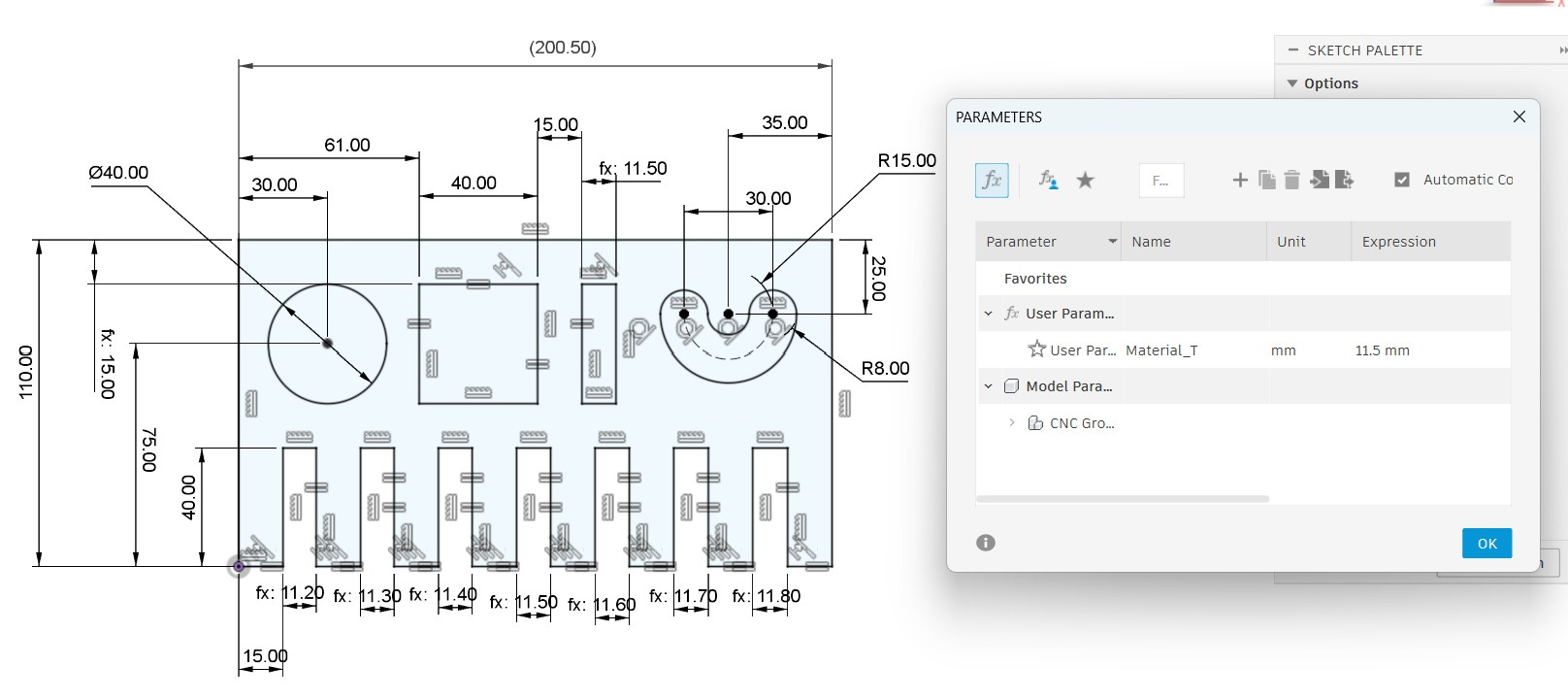
Fusion 360
We design the testing file to test our CNC millilng machine by using the Fusion 360 software
After designing it set the dimensions for testing the workpiece outcome.
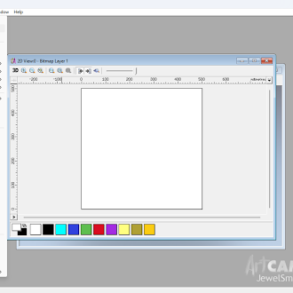
Artcam
For the tool path generation we used the Artcam software
We upload the file into the software and setting up the required parameters
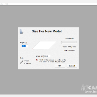
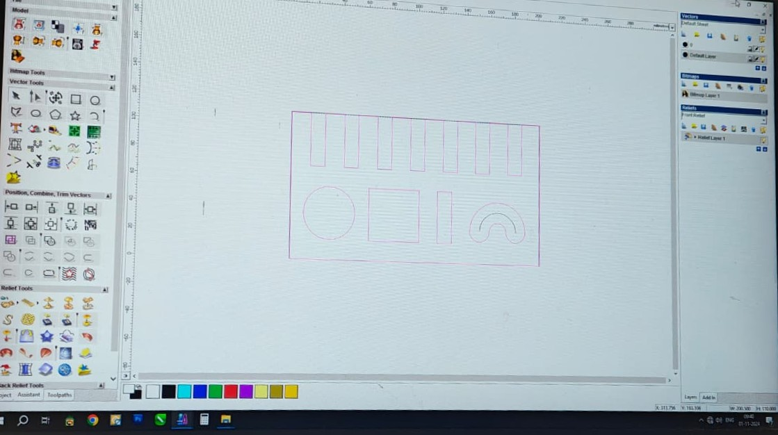
Then we converted it into gcode for the milling operation.
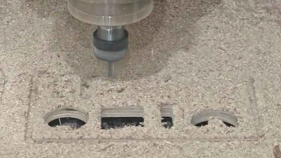
Machining
Workholding and Fixturing
Proper fixturing is important to prevent vibration and movement during machining.
- The 12 mm plywood sheet was placed parallel to the CNC machine bed.
- The workpiece was secured using C-clamps at multiple locations.
- The clamps were positioned away from the cutting path to avoid tool collisions.
- Before machining, the material was checked manually to ensure there was no movement.
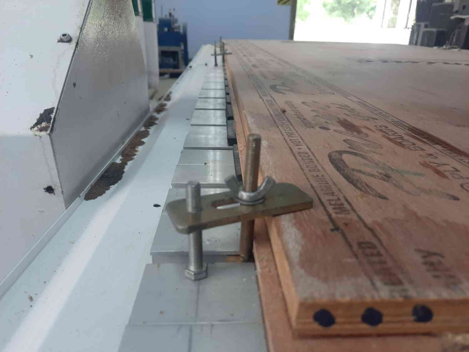
To ensure the plywood remained completely flat during machining, the sheet was first visually inspected for warping before mounting. The material was then pressed firmly against the sacrificial spoilboard while tightening the C-clamps around the perimeter. Multiple clamps were used to distribute the holding force evenly across the sheet. Before starting the machining operation, we manually checked several locations across the plywood surface to verify that no gaps existed between the material and the spoilboard. This ensured that the workpiece remained flat and prevented variations in cutting depth during machining.
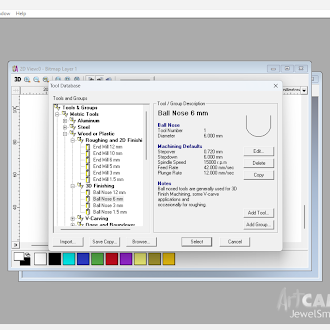
Tool Selection
For this machining test, a 6 mm flat end mill was selected as the cutting tool.
- Suitable for machining plywood materials.
- Provides clean profile and contour cutting.
- Offers a good balance between cutting speed and tool rigidity.
Machining Parameters
| Parameter | Value |
|---|---|
| Material | 12 mm Plywood |
| Tool Diameter | 6 mm End Mill |
| Spindle Speed | 12,000 RPM |
| Feed Rate | 1,500 mm/min |
| Depth per Pass | 6 mm |
Dimension Checking
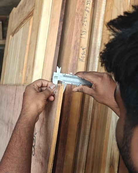
After completing the machining process, a dimensional inspection was carried out to evaluate the accuracy of the fabricated components. A Vernier caliper was used to measure the critical dimensions of the machined parts and compare them with the original CAD design values.
The inspection primarily focused on the finger joints, as they play a significant role in determining the assembly quality and fit between mating components. During the design stage, a clearance allowance of approximately 0.1 mm was incorporated to compensate for machining tolerances and material behavior.
The designed finger joint dimensions ranged from 11.2 mm to 11.8 mm. Each finger joint was individually measured using the Vernier caliper, and the recorded values were compared with the intended design dimensions to identify any deviations introduced during the machining process.
The measurements indicated that the fabricated parts closely matched the CAD design dimensions, confirming the dimensional accuracy of the CNC milling machine and the effectiveness of the selected machining parameters.
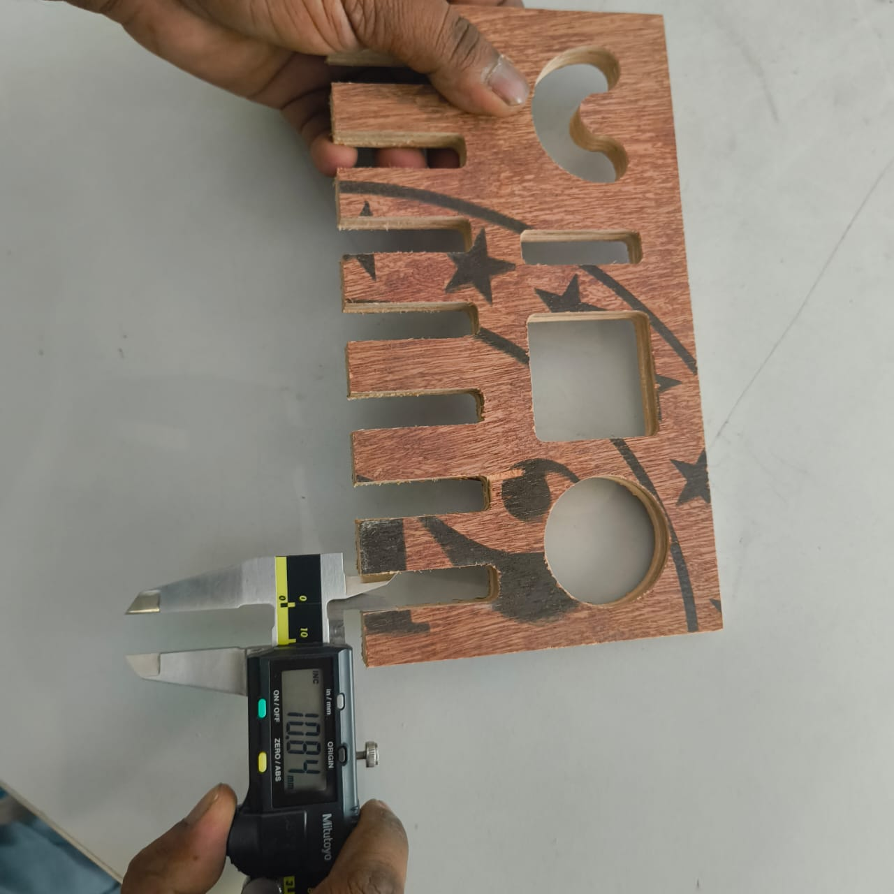
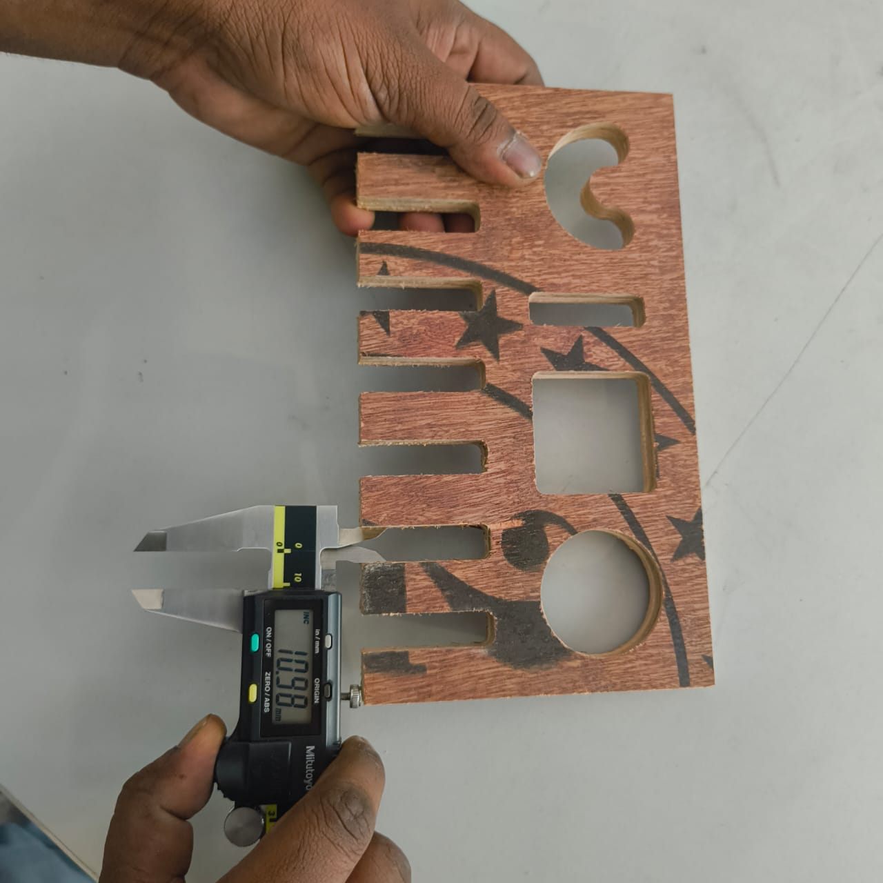
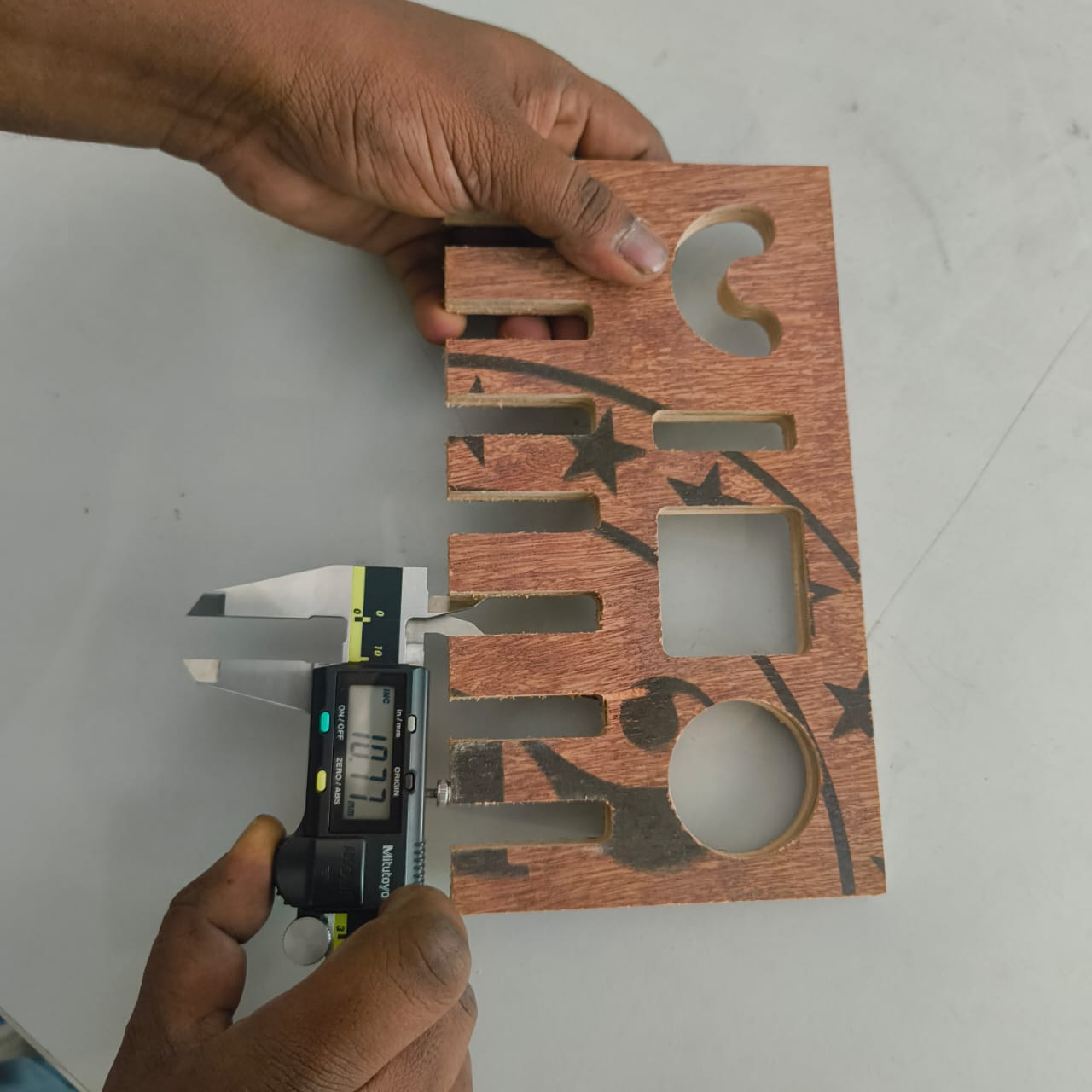
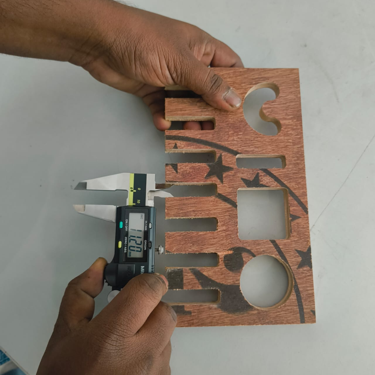
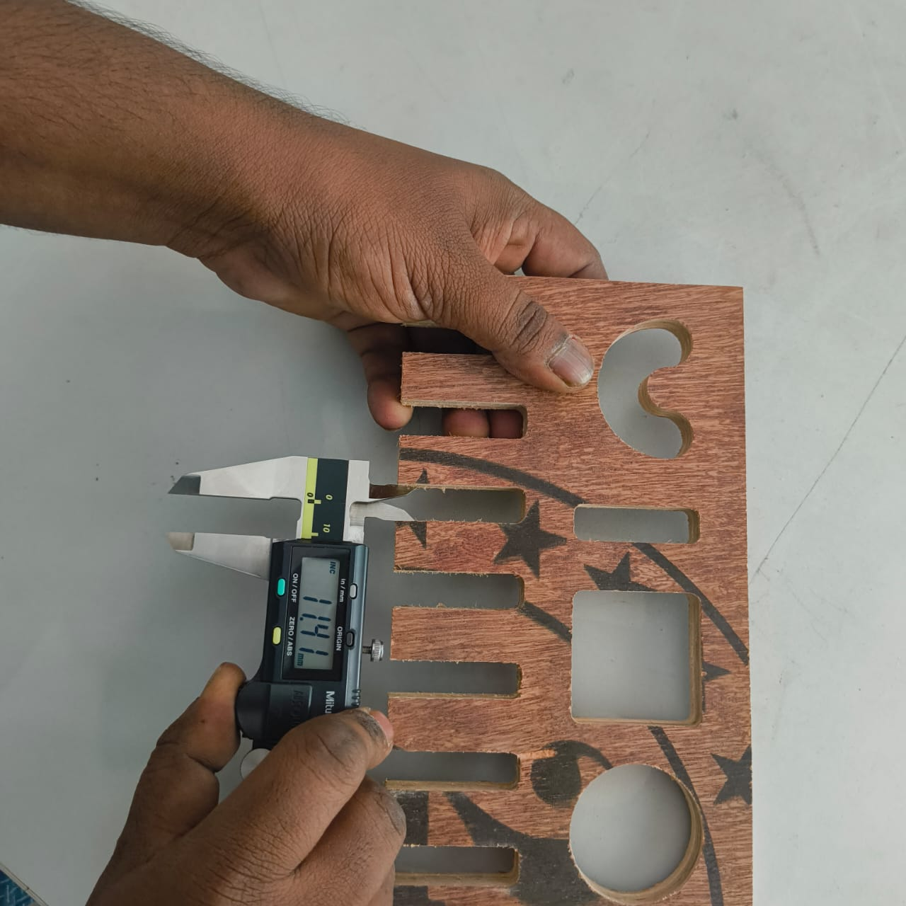
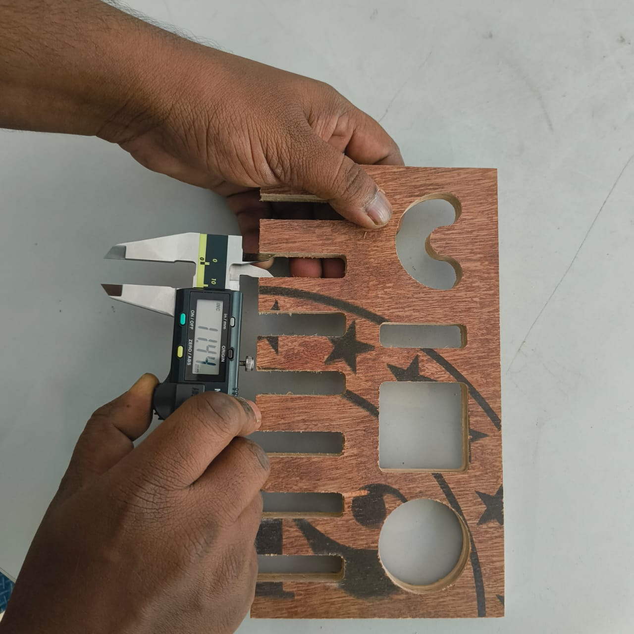
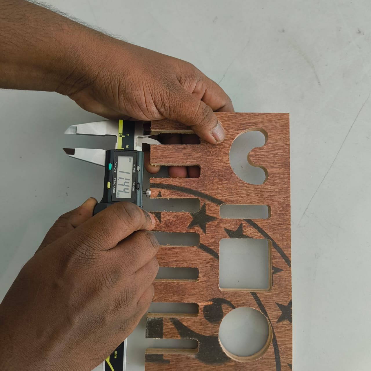
As per the finsihed outcome 11.4 and 11.5 are good to fit we find out.
Reference Files
Here is our CNC wood routing machine testing file Download