Final Project Documentation
Line Bot – Indoor Payload Delivery Robot
Line Bot
Line Bot - Smarter Than Your Average Cart
Concept Idea
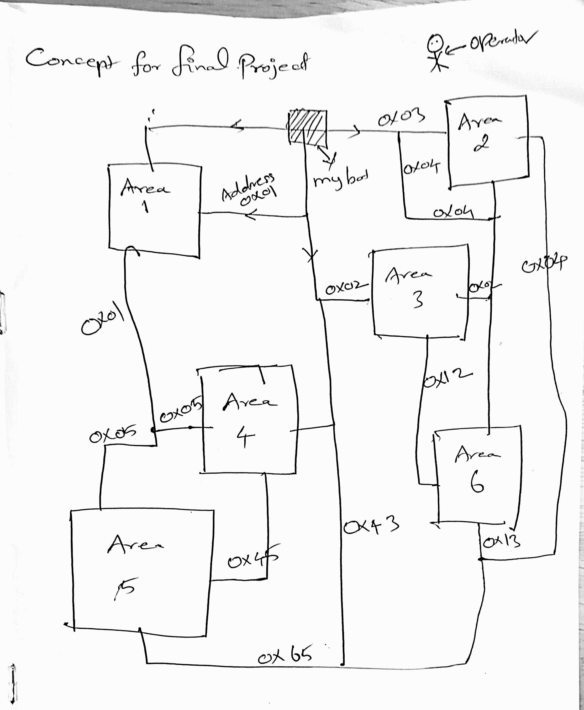
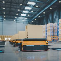
"What we are gonna do is not the Normal thing. Just like How we're gonna home, We have some pathway to go. We have a thing on Top of our head to do that. Like wise we are gonna put that thing to understand the bot to move to the area, where should go. It like putting an RFID Reader there by If we put the tag then It will capture data and then it will move from that area where we have address in each trace".
Jump to System Integeration
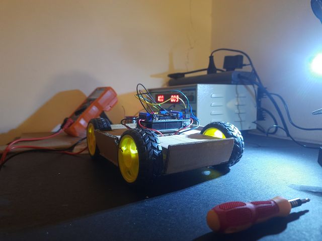
Initial Model
Final project presentation video

1. Introduction and Motivation
The Line Bot is an autonomous, line-following mobile robot developed as the final project for the Fab Academy 2025 cycle. The motivation behind the project is to demonstrate how embedded systems, digital fabrication, and sensor-actuator integration can be combined into a compact, educational robotics platform.
Autonomous robots that can follow a designated path are often the first step in teaching robotic behavior, path planning, and feedback-based control systems. The project embodies this concept while enhancing it with modern tools like custom PCB design, ESP32-based microcontroller integration, and real-time data display through an OLED interface.
The bot showcases the fusion of mechanical, electrical, and programming skills required in modern embedded product development.
2. Project Objectives
The primary goals of the Line Bot project include:
- To design and fabricate a compact robot that can follow a line autonomously using IR sensors.
- To develop a custom microcontroller-based electronics system using the XIAO ESP32-C3.
- To fabricate a custom PCB integrating motor drivers and IR sensors.
- To implement reliable line-following logic using PWM and real-time feedback.
- To visualize sensor data using an onboard OLED display.
- To validate the system through performance testing in different conditions.
- To document all aspects of design, development, testing, and learning.
Line Follower Bot Gantt Chart
Subsystem 1: Mechanical Design and Fabrication
| Task | Week 1 | Week 2 | Week 3 | Week 4 |
|---|---|---|---|---|
| Rough Sketch | ||||
| CAD Modelling | ||||
| Component Selection | ||||
| 3D Printing | ||||
| Assembly & Fitting |
Subsystem 2: On-Bot PCB Design
| Task | Week 1 | Week 2 | Week 3 | Week 4 |
|---|---|---|---|---|
| Schematic Design | ||||
| Power Calculation | ||||
| PCB Layout | ||||
| Fabrication & Testing |
Subsystem 3: Sensor + Line Following Logic
| Task | Week 1 | Week 2 | Week 3 | Week 4 |
|---|---|---|---|---|
| IR Sensor Calibration | ||||
| Threshold Tuning | ||||
| Tracking Algorithm |
Subsystem 4: Bot Control Software
| Task | Week 1 | Week 2 | Week 3 | Week 4 |
|---|---|---|---|---|
| PWM + PID Setup | ||||
| Motor Control Logic | ||||
| Serial Debug + Logs |
Subsystem 5: Testing and Final Tuning
| Task | Week 1 | Week 2 | Week 3 | Week 4 |
|---|---|---|---|---|
| Integration Test | ||||
| Performance Test | ||||
| Final Field Run |
3. Functional Requirements
| Requirement | Achieved | Notes |
|---|---|---|
| Follow black line | Yes | Fast response achieved after PID tuning |
| Autonomous delivery path | Yes | Closed-loop control |
| Stable & rugged chassis | Yes | Acrylic + 3D printed mounts |
| Battery powered operation | Yes | 11.1V supply |
| Upgrade capability | Yes | BLE control reserved on PCB |
4. Bill of Materials in $
| S. No | Component | Description | Qty | Unit Price (USD) | Total Price (USD) |
|---|---|---|---|---|---|
| 1 | XIAO ESP32-C3 | Microcontroller Unit | 1 | 5.50 | 5.50 |
| 2 | Fabricated PCBs | Custom Motor + Sensor Interface | 2 | 2.00 | 4.00 |
| 3 | Header Pins & Wires | Male/Female Headers, Solder Wires | 1 set | 1.00 | 1.00 |
| 4 | BO Motors + Wheels | Plastic Gear Motors with Wheels | 2 sets | 2.50 | 5.00 |
| 5 | L298N Motor Driver | Dual H-Bridge Driver Module | 2 | 2.00 | 4.00 |
| 6 | Connector Wires + JST | JST 2/7-pin wires & terminals | 2 sets | 1.00 | 2.00 |
| 7 | OLED Display | 0.96" I2C Monochrome | 1 | 3.00 | 3.00 |
| 8 | 5-Line Sensor Array | IR Line Detection Module | 1 | 4.00 | 4.00 |
| 9 | Acrylic Sheet | 100x100 mm Chassis Base | 1 | 1.50 | 1.50 |
| 10 | Line Marker Tape | Black Tape for Path | 1 roll | 0.50 | 0.50 |
| 10 | 3D Printing filament | PLA | 1 Spool | 10 | 10.00 |
| Total Cost | $40.00 | ||||
5. System Architecture
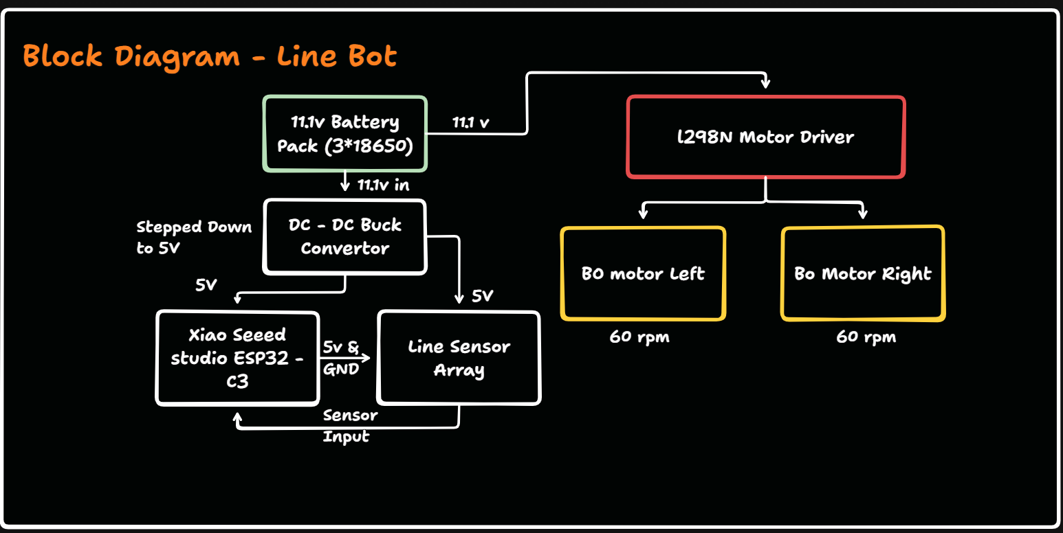
All circuits share Common Ground to ensure stable logic references.
6. Mechanical Design
The body of the robot was designed in CAD and laser cut using 3mm acrylic sheet. The design considerations included:
- Adequate spacing between wheels and sensors.
- Firm placement of motor driver and MCU.
- Slots for wiring and connectors.
- Mounting holes for sensors to face the ground at a proper angle.
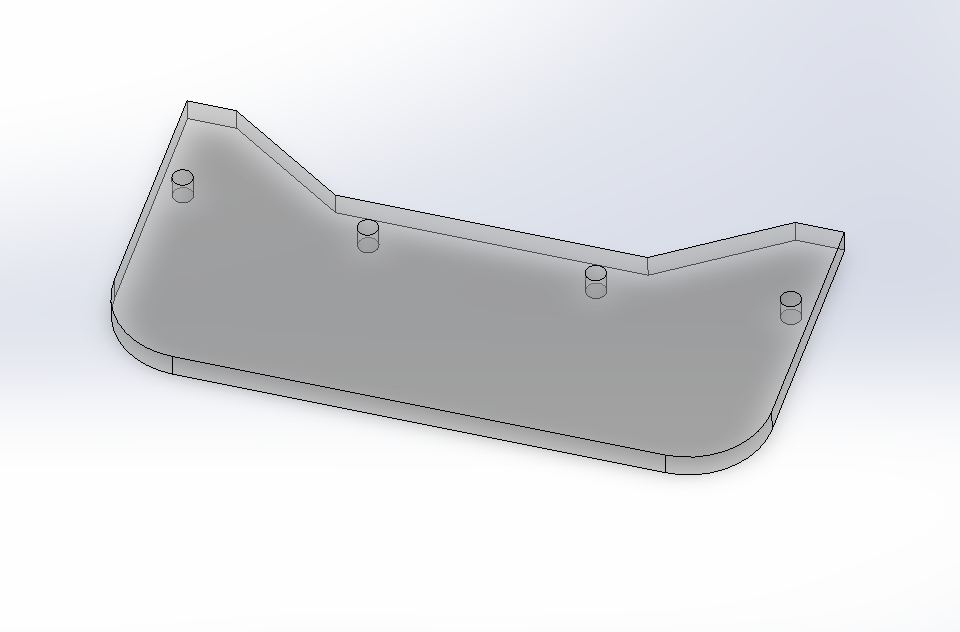
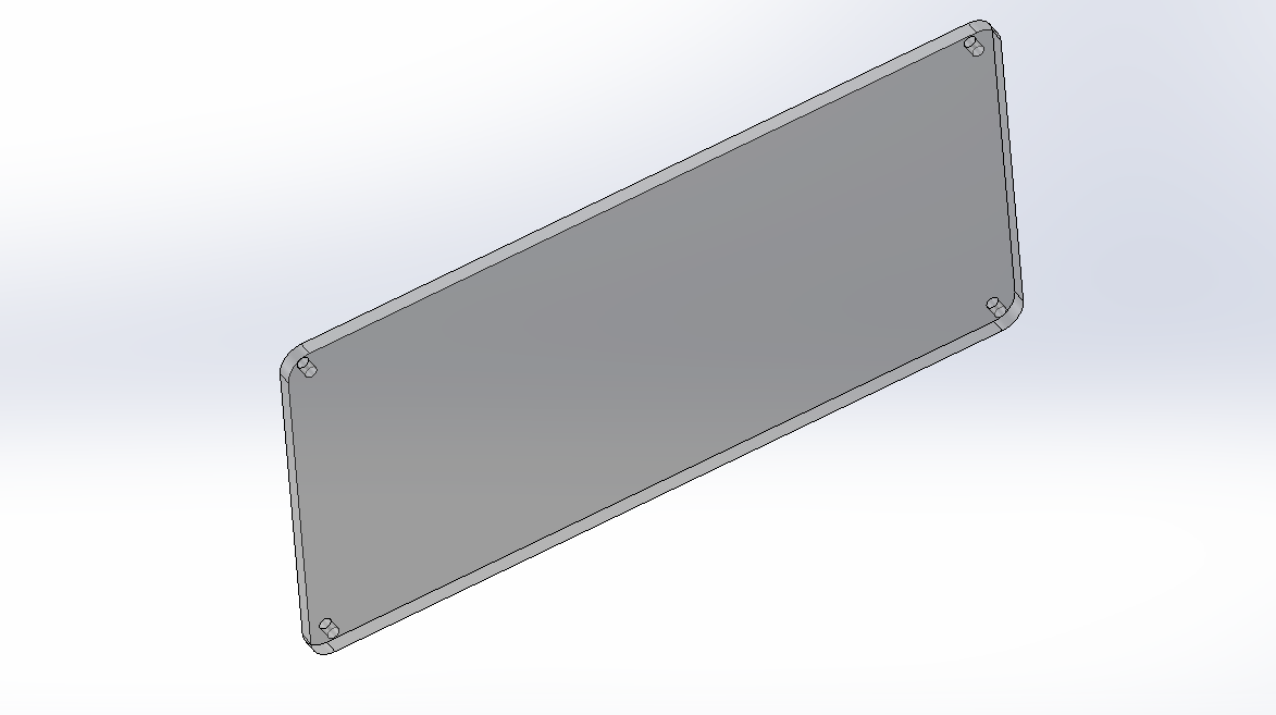
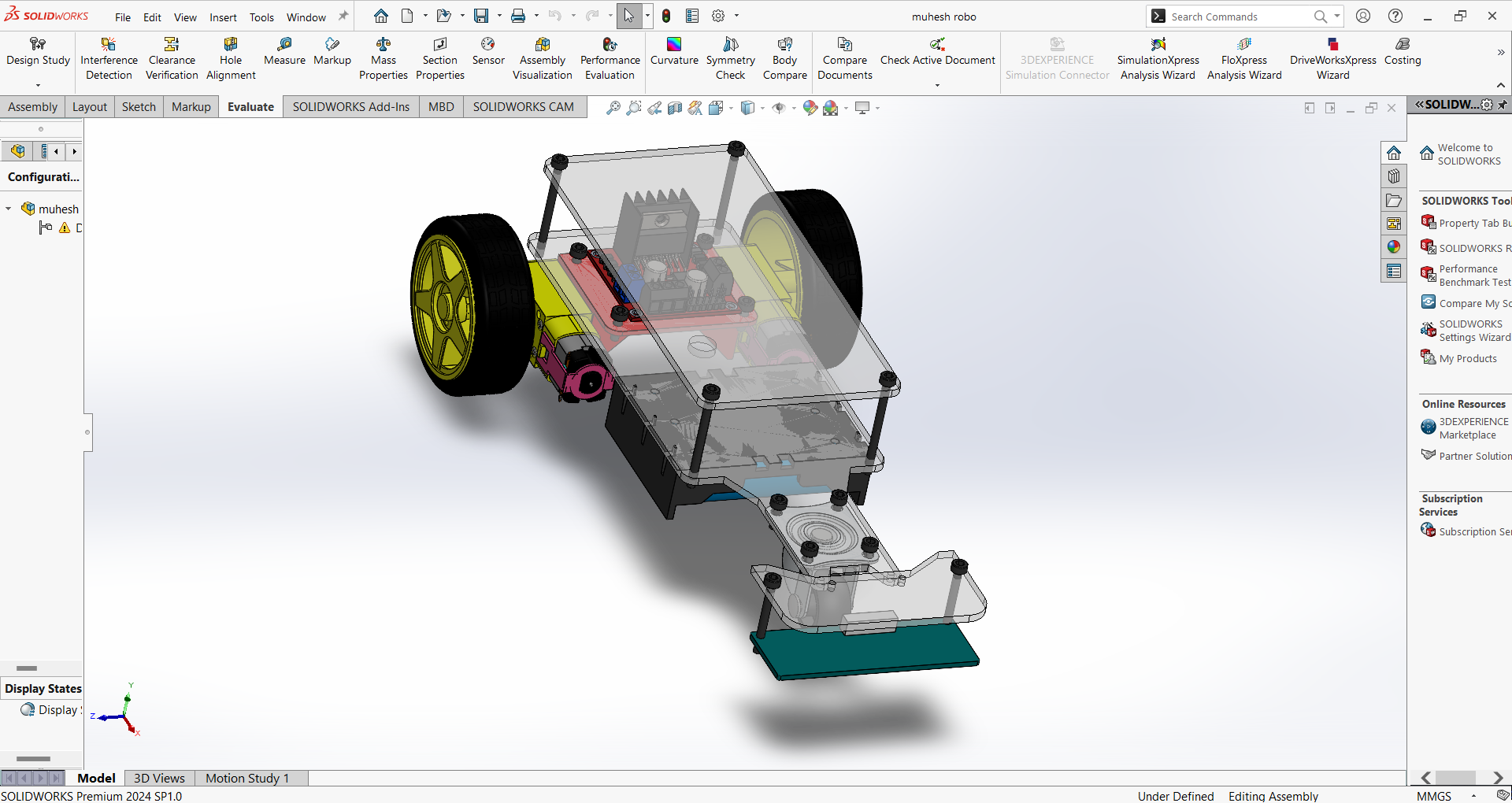
3D Design
Chassis Design and Sensor base plate attachment Design. I have designed the chassis and sensor base plate attachment using SolidWorks
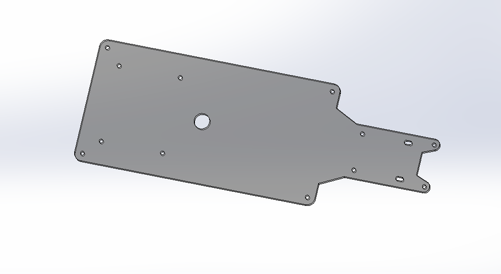
Then I have imported the 3d Design which already exists in Online GrabCAD
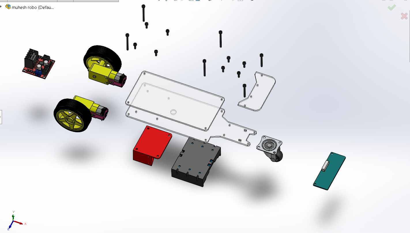
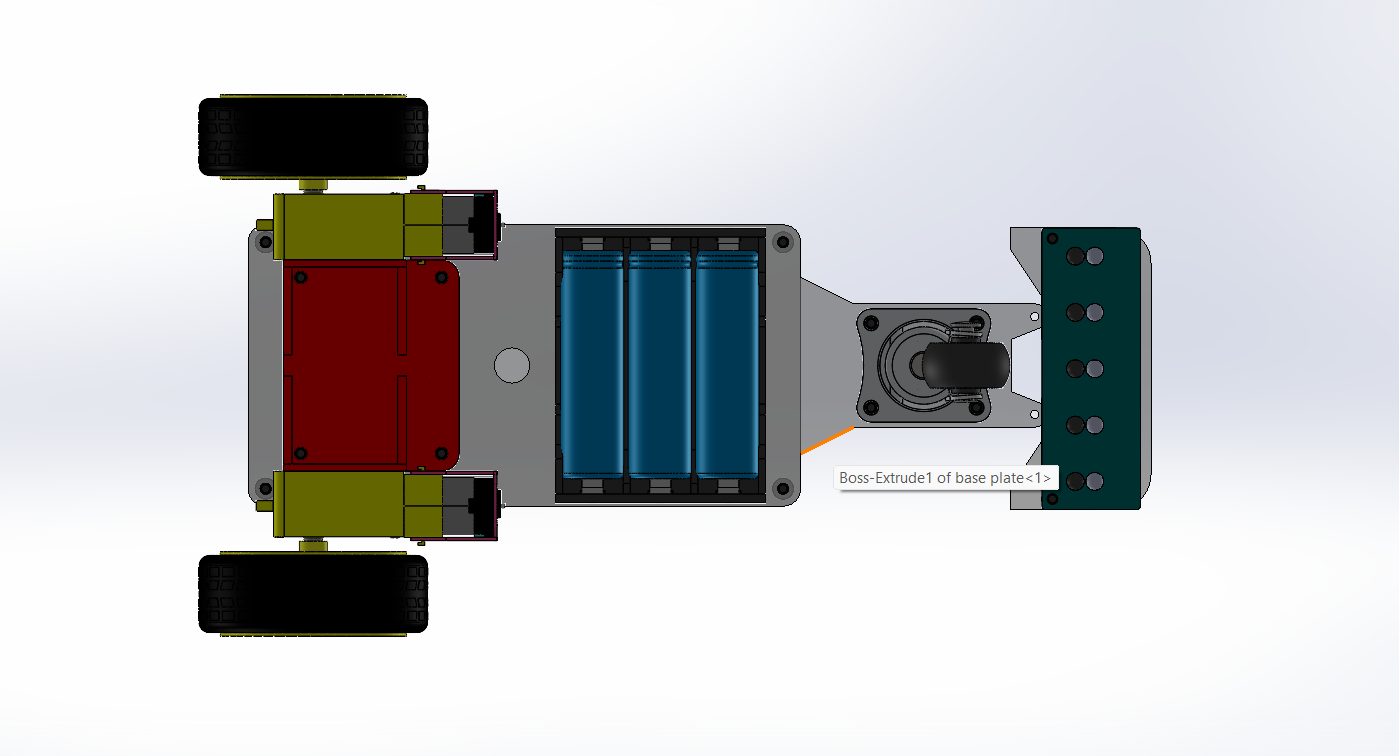
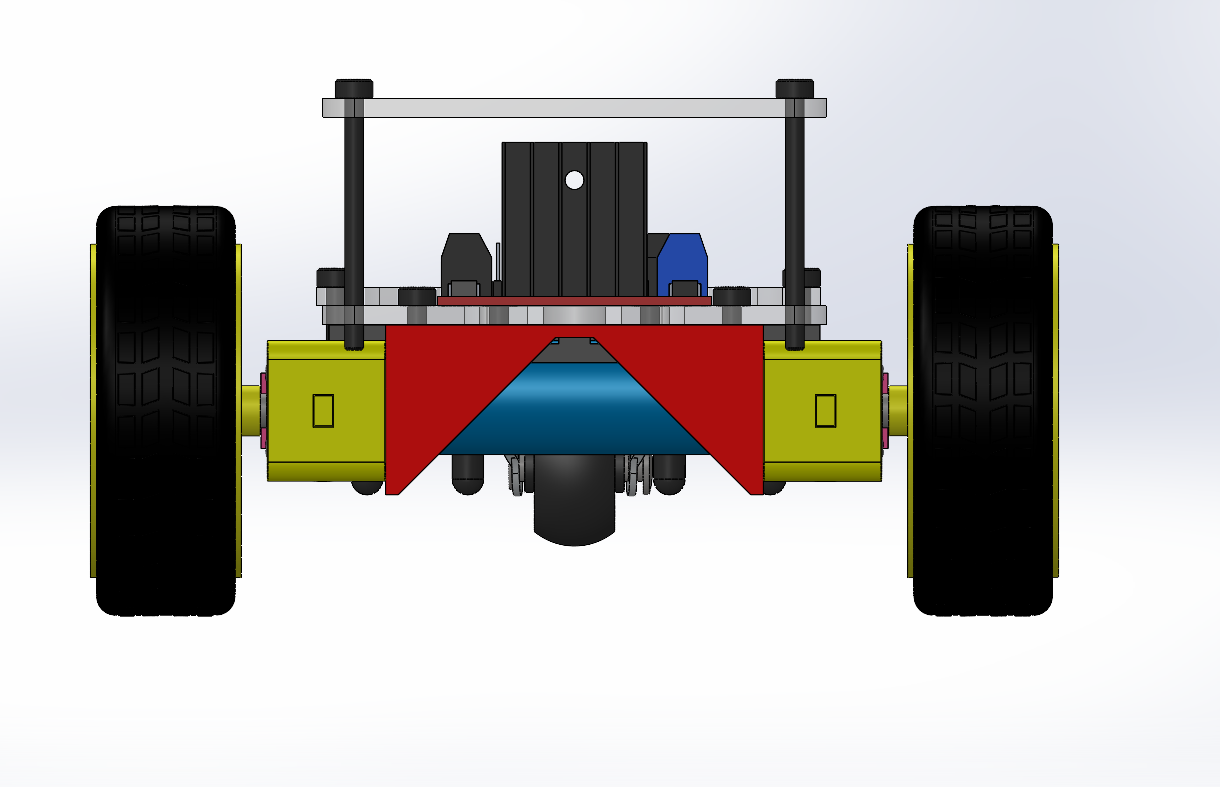
Then I have Assembled all the parts and Created the Final Model
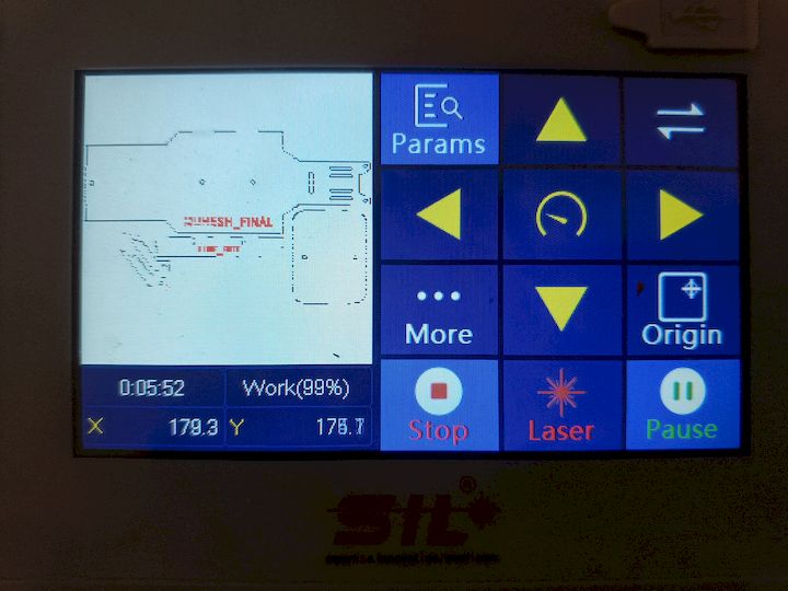
7. Laser Cutting Process
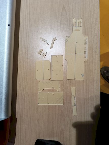
The BO motors were mounted using acrylic brackets, and the IR sensor array was placed at the front underside. The final structure ensured good balance, durability, and access for debugging.
8. Electronics Design
A complete single-layer SMD PCB was designed:
- Schematic Diagram of my Circuit which mainly focused on the Sensor Array
- Power regulation input
- JST connectors for:
- Motor control pins → L298N
- Sensor digital inputs (5 signals)
- 5V regulated output to sensors
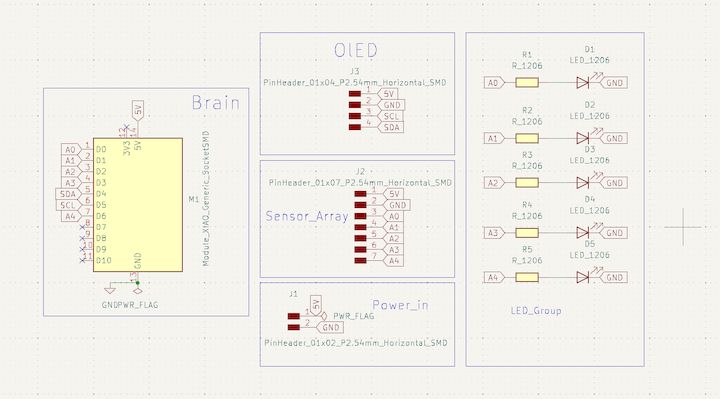
Schematic to PCB design
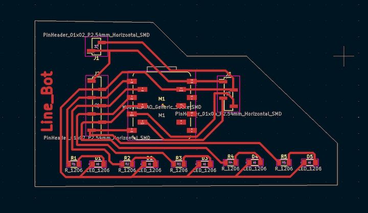
Fabrication Process:
- Designed in KiCad
- Milled in FabLab PCB machine
- Fully SMD assembly performed manually
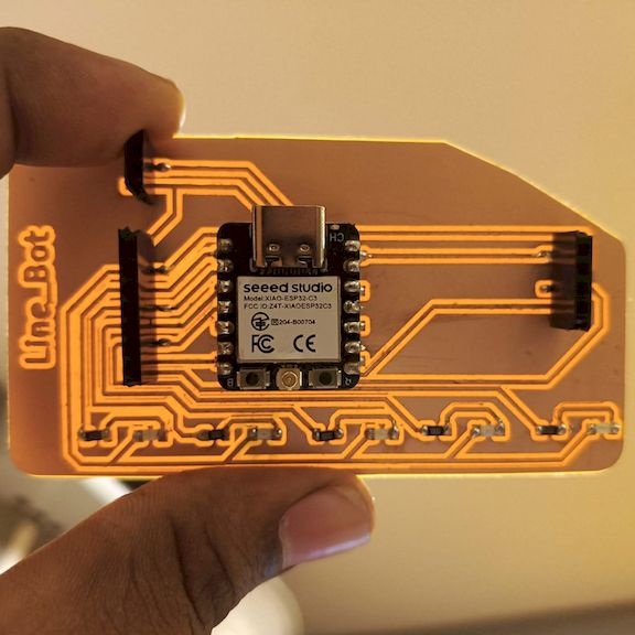
The system wiring was planned carefully to ensure minimal noise, secure connections, and clear power/data paths. The use of JST connectors simplified replacements and debugging.
Design decisions focused on minimizing space, ensuring low EMI, and clean signal routing. The board was fabricated using PCB milling tools in the Fab Lab, and then soldered by hand. Careful routing allowed a single-layer PCB, reducing cost and complexity.
Testing was conducted using multimeters, continuity tests, and live firmware to confirm all traces and headers were correctly connected before integration.
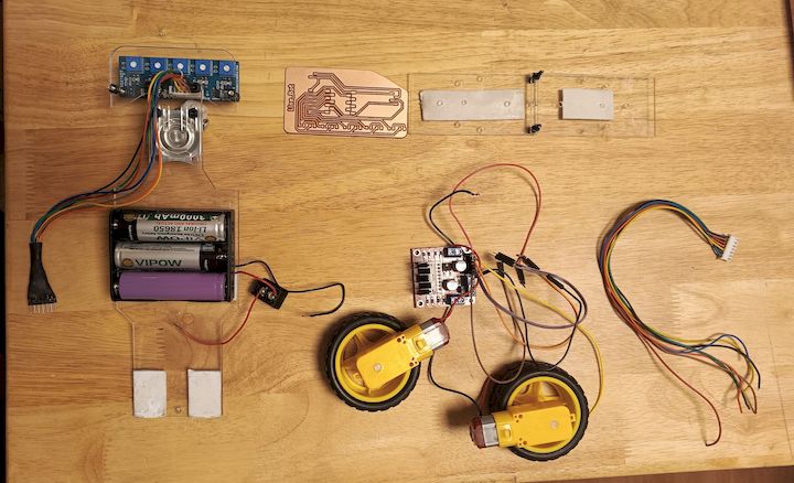
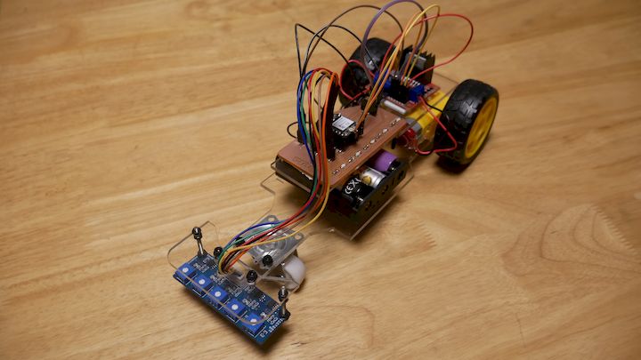
9. Assembly Process
The mechanical and electrical systems were integrated step-by-step:
- Chassis Construction: Laser-cut acrylic parts were assembled using bolts and plastic spacers to form the robot frame.
- Motor Mounting: BO motors were attached to the chassis using acrylic brackets and secured with fasteners.
- PCB Installation: The custom PCB was fixed to the frame with standoffs and screws to minimize vibration.
- Sensor and Display Setup: The IR sensor module was mounted at the front bottom, and the OLED was fixed on the top for easy visibility.
- Wiring and Connections: JST connectors and male-female headers were used for quick plug-and-play setup.
- Battery Housing: The Li-ion battery and its holder were placed centrally to maintain weight balance.
All systems were connected and verified using multimeter continuity checks and boot-time LED indicators.
Assembly Video
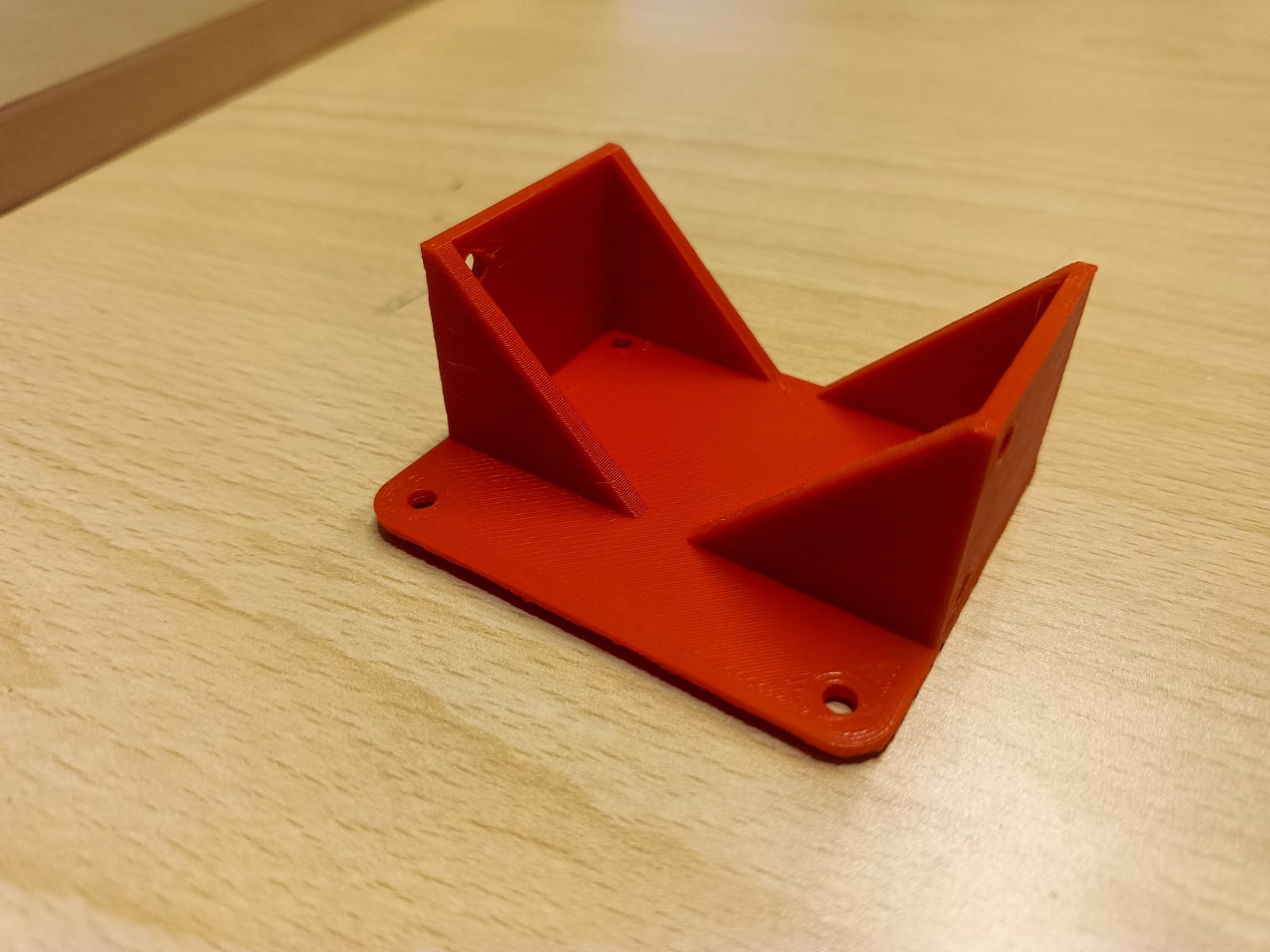
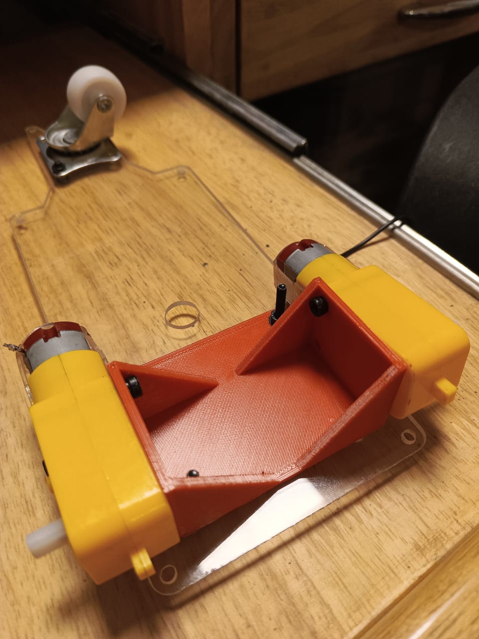
Some Failures occured in wheels while connecting the motors to the chassis. So I additionally attached the motors to the chassis using 3D printed brackets.
9. Pin Connection Details
| ESP32-C3 Pin | Connected To | Function |
|---|---|---|
| D1 | Motor A IN1 | Left motor forward/reverse |
| D2 | Motor A IN2 | Left motor direction |
| D3 | Motor B IN3 | Right motor forward/reverse |
| D4 | Motor B IN4 | Right motor direction |
| D5 | Sensor S0 | Left-most |
| D6 | Sensor S1 | Slight left |
| D7 | Sensor S2 | Center |
| D8 | Sensor S3 | Slight right |
| D9 | Sensor S4 | Right-most |
Common Ground between all modules
10. Software Development
Programming Platform: Arduino IDE
Control Algorithm: PID-based differential drive
Key logic:
- Line array outputs 5 digital signals
- Weighted error calculated for correction
- Motor speeds varied accordingly:
- Left fast / Right slow → Turn right
- Right fast / Left slow → Turn left
Sensor Calibration
I have used a code to calibrate the sensors. which shows the output as when the sensor is on the line it keeps on.
                            #define S1 D0
                            #define S2 D1
                            #define S3 D2
                            #define S4 D3
                            #define S5 D4

                            void setup() {
                            Serial.begin(115200);
                            pinMode(S1, INPUT);
                            pinMode(S2, INPUT);
                            pinMode(S3, INPUT);
                            pinMode(S4, INPUT);
                            pinMode(S5, INPUT);
                            }

                            void loop() {
                            Serial.print(digitalRead(S1)); Serial.print(" ");
                            Serial.print(digitalRead(S2)); Serial.print(" ");
                            Serial.print(digitalRead(S3)); Serial.print(" ");
                            Serial.print(digitalRead(S4)); Serial.print(" ");
                            Serial.println(digitalRead(S5));
                            delay(200);
                            }
Motor Testing and Calibration
To know the motor maximum consumption I have tested motor at various PWM values and then and that supports the pin connection I have given to the code
                            #define ENA D6
                            #define IN1 D7
                            #define IN2 D5
                            #define ENB D10
                            #define IN3 D9
                            #define IN4 D8

                            int testSpeed = 120;   // Safe test speed

                            void setup() {
                            Serial.begin(115200);
                            Serial.println("Motor Test Starting...");

                            pinMode(ENA, OUTPUT);
                            pinMode(IN1, OUTPUT);
                            pinMode(IN2, OUTPUT);

                            pinMode(ENB, OUTPUT);
                            pinMode(IN3, OUTPUT);
                            pinMode(IN4, OUTPUT);
                            }

                            void forward(int speedL, int speedR) {
                            digitalWrite(IN1, HIGH);
                            digitalWrite(IN2, LOW);
                            digitalWrite(IN3, HIGH);
                            digitalWrite(IN4, LOW);

                            analogWrite(ENA, speedR);
                            analogWrite(ENB, speedL);
                            }

                            void backward(int speedL, int speedR) {
                            digitalWrite(IN1, LOW);
                            digitalWrite(IN2, HIGH);
                            digitalWrite(IN3, LOW);
                            digitalWrite(IN4, HIGH);

                            analogWrite(ENA, speedR);
                            analogWrite(ENB, speedL);
                            }

                            void leftTurn() {
                            digitalWrite(IN1, LOW);
                            digitalWrite(IN2, HIGH);
                            digitalWrite(IN3, HIGH);
                            digitalWrite(IN4, LOW);

                            analogWrite(ENA, testSpeed);
                            analogWrite(ENB, testSpeed);
                            }

                            void rightTurn() {
                            digitalWrite(IN1, HIGH);
                            digitalWrite(IN2, LOW);
                            digitalWrite(IN3, LOW);
                            digitalWrite(IN4, HIGH);

                            analogWrite(ENA, testSpeed);
                            analogWrite(ENB, testSpeed);
                            }

                            void stopMotor() {
                            analogWrite(ENA, 0);
                            analogWrite(ENB, 0);
                            }

                            void loop() {

                                Serial.println("Forward");
                                forward(testSpeed, testSpeed);
                                delay(2000);

                                Serial.println("Backward");
                                backward(testSpeed, testSpeed);
                                delay(2000);

                                Serial.println("Left");
                                leftTurn();
                                delay(2000);

                                Serial.println("Right");
                                rightTurn();
                                delay(2000);

                                Serial.println("Stop");
                                stopMotor();
                                delay(2000);
                            }
Final Working Code
                            // Line Sensors
                            #define S1 D0   // GPIO2
                            #define S2 D1   // GPIO3
                            #define S3 D2   // GPIO4
                            #define S4 D3   // GPIO5
                            #define S5 D4   // GPIO6

                            // Motor Driver (L298N)
                            // Right Motor
                            #define ENA D6   // GPIO21 (PWM OK)
                            #define IN1 D7   // GPIO20
                            #define IN2 D5   // GPIO7

                            // Left Motor
                            #define ENB D10  // GPIO10 (PWM OK)
                            #define IN3 D9   // GPIO9
                            #define IN4 D8   // GPIO8


                            int baseSpeed = 110;
                            int turnSpeed = 90;


                            void setup() {
                            Serial.begin(115200);

                            pinMode(ENA, OUTPUT);
                            pinMode(IN1, OUTPUT);
                            pinMode(IN2, OUTPUT);

                            pinMode(ENB, OUTPUT);
                            pinMode(IN3, OUTPUT);
                            pinMode(IN4, OUTPUT);

                            pinMode(S1, INPUT);
                            pinMode(S2, INPUT);
                            pinMode(S3, INPUT);
                            pinMode(S4, INPUT);
                            pinMode(S5, INPUT);

                            Serial.println("Line Follower Ready");
                            }


                            void drive(int left, int right) {

                            if (right >= 0) {
                                digitalWrite(IN1, HIGH);
                                digitalWrite(IN2, LOW);
                            } else {
                                digitalWrite(IN1, LOW);
                                digitalWrite(IN2, HIGH);
                            }

                            if (left >= 0) {
                                digitalWrite(IN3, HIGH);
                                digitalWrite(IN4, LOW);
                            } else {
                                digitalWrite(IN3, LOW);
                                digitalWrite(IN4, HIGH);
                            }

                            analogWrite(ENA, abs(right));
                            analogWrite(ENB, abs(left));
                            }

                            void stopMotor() {
                            analogWrite(ENA, 0);
                            analogWrite(ENB, 0);
                            }

                            void loop() {

                            int s1 = digitalRead(S1);
                            int s2 = digitalRead(S2);
                            int s3 = digitalRead(S3);
                            int s4 = digitalRead(S4);
                            int s5 = digitalRead(S5);

                            Serial.print(s1); Serial.print(" ");
                            Serial.print(s2); Serial.print(" ");
                            Serial.print(s3); Serial.print(" ");
                            Serial.print(s4); Serial.print(" ");
                            Serial.println(s5);

                            if (s3 == 1) {
                                drive(baseSpeed, baseSpeed);
                            }
                            else if (s4 == 1 || s5 == 1) {
                                drive(baseSpeed - turnSpeed, baseSpeed + turnSpeed);
                            }
                            else if (s2 == 1 || s1 == 1) {
                                drive(baseSpeed + turnSpeed, baseSpeed - turnSpeed);
                            }
                            else {
                                stopMotor();
                            }

                            delay(5);
                            }
11. Major Failures & Learnings
| Issue Faced | Cause | Fix Implemented | Learning |
|---|---|---|---|
| Slow turning and lane loss | Weak motor correction | PID tuning + increased PWM | Closed-loop tuning is crucial |
| Sensor instability | Noise from motors | Twisted ground + separate power for sensors | EMI grounding principles |
| ESP32-C3 reset during turns | Current surge from motors | Added decoupling + capacitor | Power integrity matters |
| Line not detected consistently | Sensor too high | Height lowered to 8–10 mm | Proper sensing geometry |
| Overshooting at intersections | Delay in switching logic | Faster sampling rate | Real-time control importance |
These failures significantly improved final performance.
12. Testing Procedure
Testing area: Smooth white floor with black electrical tape path
Track included:
- Straight paths
- Multiple turns
- Tight curves
- Cross-line situations
Tracking Performance:
- Fast speed with smooth corrections
- Accurately follows intersections by prioritizing center signal
- Recover behavior: realigns if line temporarily lost
13. Safety Measures
- Battery protection module for 18650 cells
- Proper insulation of high-current lines
- Chassis edges rounded during laser cutting
14. Final Results
| Feature | Result |
|---|---|
| Speed | Fast and stable |
| Accuracy | Consistent on sharp turns & curves |
| Line Intersection | Successfully handled |
| Runtime | 60+ minutes |
| System Reliability | High |
15. Learning Outcomes
- Embedded control
- PCB design & manufacturing
- Motor actuation & differential drive
- Laser cutting + 3D printing
- Power distribution + EMI isolation
- PID control tuning
- System-level integration
16. Future Improvements
| Upgrade | Benefit |
|---|---|
| Bluetooth App Control | Remote override |
| Higher torque motors & metal chassis | Payload up to 25 kg |
| Additional sensors (ToF, Ultrasonic) | Obstacle avoidance |
| Mapping + QR navigation | Intelligent AMR |
This prototype forms the foundation for a commercial mobile delivery robot.
17. Conclusion
The Line Bot successfully demonstrates a functional autonomous line-guided delivery robot. The custom electronics, tuned control system, and optimized mechanical design enabled high-speed and accurate tracking. This project meets the Fab Academy goal of designing, prototyping, and documenting a complete integrated system, while establishing a roadmap for real-world deployment.
Project Files and Resources
To ensure reproducibility and open-source accessibility, all design files, source code, and project documentation related to the Line Bot project are provided below. These files allow anyone to understand, modify, fabricate, and further develop the system.
Source Code
Electronics Design Files
Mechanical Design Files
All files have been developed as part of the Fab Academy final project and are provided to support documentation, replication, future development, and educational use.