- Week 1 : Project Management
- Week 2 : Computer-aided
- Week 3 : Computer Controlled Cutting
- Week 4 : Embedded Programming
- Week 5 :3D Scanning and Printing
- Week 6 : Electronic Design
- Week 7 : Computer Controlled Machining
- Week 8 : Electronics Production
- Week 9 : Input Devices
- Week 10 : Output Devices
- Week 11 : Networking and Communication
- Week 12 : Mechanical Design and Machine Design
- Week 14 : Molding and Casting
- Week 15 : Interface and Application Programming
- Week 16 : System Integeration
- Week 17 : Wildcard Week
- Week 18 : Applications and Implications, Project Development
- Week 19 : Invention, Intellectual property and Income
- Week 20 : FInal Project Requirements
Week 3 – Computer Controlled Cutting
This week's assignment focused on understanding computer-controlled cutting processes using laser cutting and vinyl cutting technologies. The workflow included kerf characterization, parametric design development, fabrication of a laser-cut construction kit, and creating custom vinyl graphics using a vinyl cutter.
Assignment Tasks
- Characterize laser cutter kerf
- Design a parametric construction kit
- Laser cut and assemble the design
- Understand LaserCAD workflow
- Create and cut a custom vinyl sticker
- Document fabrication workflow
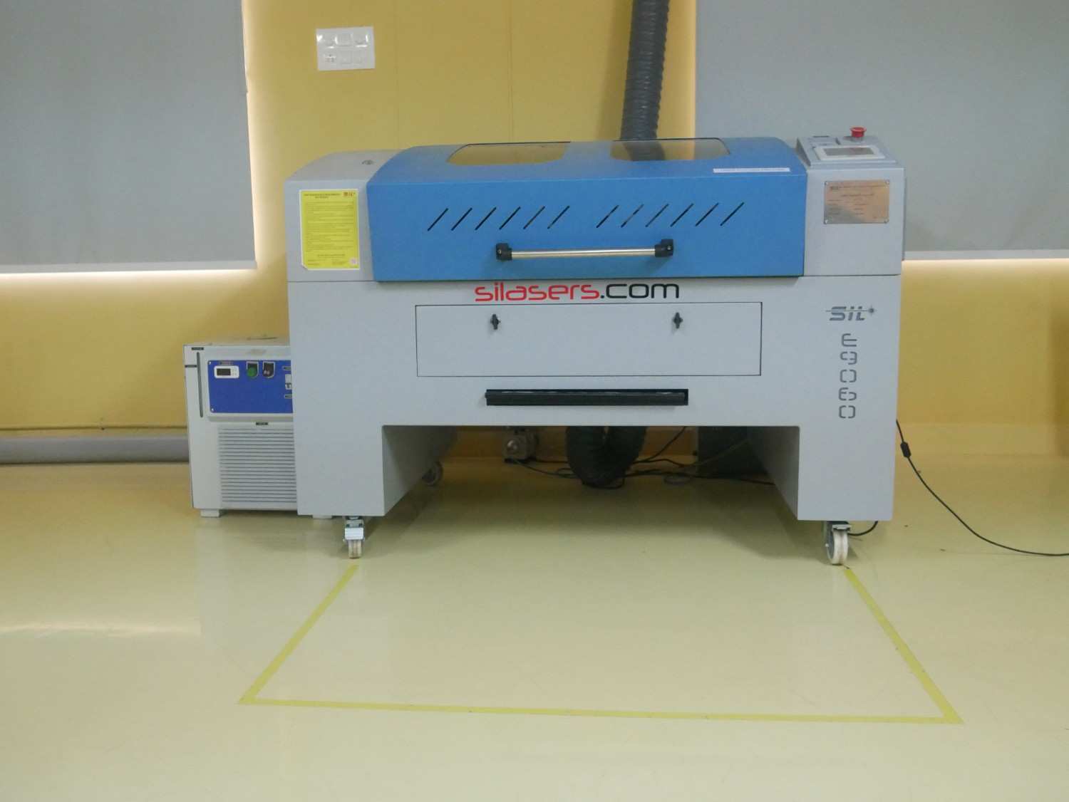
SILASERS CO₂ Laser Engraving and Cutting Machine
For this week's assignment, we used the SILASERS CO₂ Laser Engraving and Cutting Machine available in our Fab Lab for both laser cutting and engraving operations. This machine is specifically designed for high-precision processing of non-metallic materials and plays a vital role in digital fabrication workflows. It enables the direct conversion of CAD designs into physical components with excellent dimensional accuracy and repeatability.
The machine operates by focusing a high-energy CO₂ laser beam onto the material surface. Depending on the selected power and speed settings, the laser can either engrave the surface or completely cut through the material. During this assignment, the laser cutter was used for kerf characterization experiments and for fabricating the components required for the parametric lamp construction kit.
One of the major advantages of laser cutting is its ability to produce complex geometries without requiring custom tooling. Since the process is digitally controlled, modifications to the design can be quickly implemented, making it ideal for rapid prototyping and iterative product development.
Machine Specifications
| Parameter | Specification |
|---|---|
| Machine Type | CO₂ Laser Engraving and Cutting Machine |
| Manufacturer | SILASERS (Suresh Indu Lasers Pvt. Ltd.) |
| Laser Source | CO₂ Laser Tube |
| Laser Power | 100 W |
| Working Area | 1200 mm × 1200 mm |
| Cooling System | Water Cooling |
| Control System | DSP Controller |
| Maximum Cutting Speed | 30000 mm/min |
| Maximum Travel Speed | 64000 mm/min |
| Supported File Formats | DXF, AI, BMP, JPG, PNG, PLT |
| Software Compatibility | LaserCAD, CorelDRAW, AutoCAD |
| Positioning Accuracy | High Precision Motion Control |
| Applications | Laser Cutting, Engraving, Marking and Prototyping |
Understanding the machine specifications was important before beginning the cutting process, as factors such as laser power, cutting speed, focus distance, and material properties directly influence the quality of the final output. This knowledge helped in selecting appropriate parameters during kerf testing and final fabrication.
Machine Setup and Safety Precautions
After completing the design preparation in LaserCAD and generating the required cutting file, I proceeded to the SILASERS CO₂ laser cutting machine for fabrication. Before starting the cutting process, I verified the machine settings, checked the material placement, and ensured that the focus distance was properly adjusted. Proper machine setup is essential to achieve clean cuts, accurate dimensions, and safe operation.
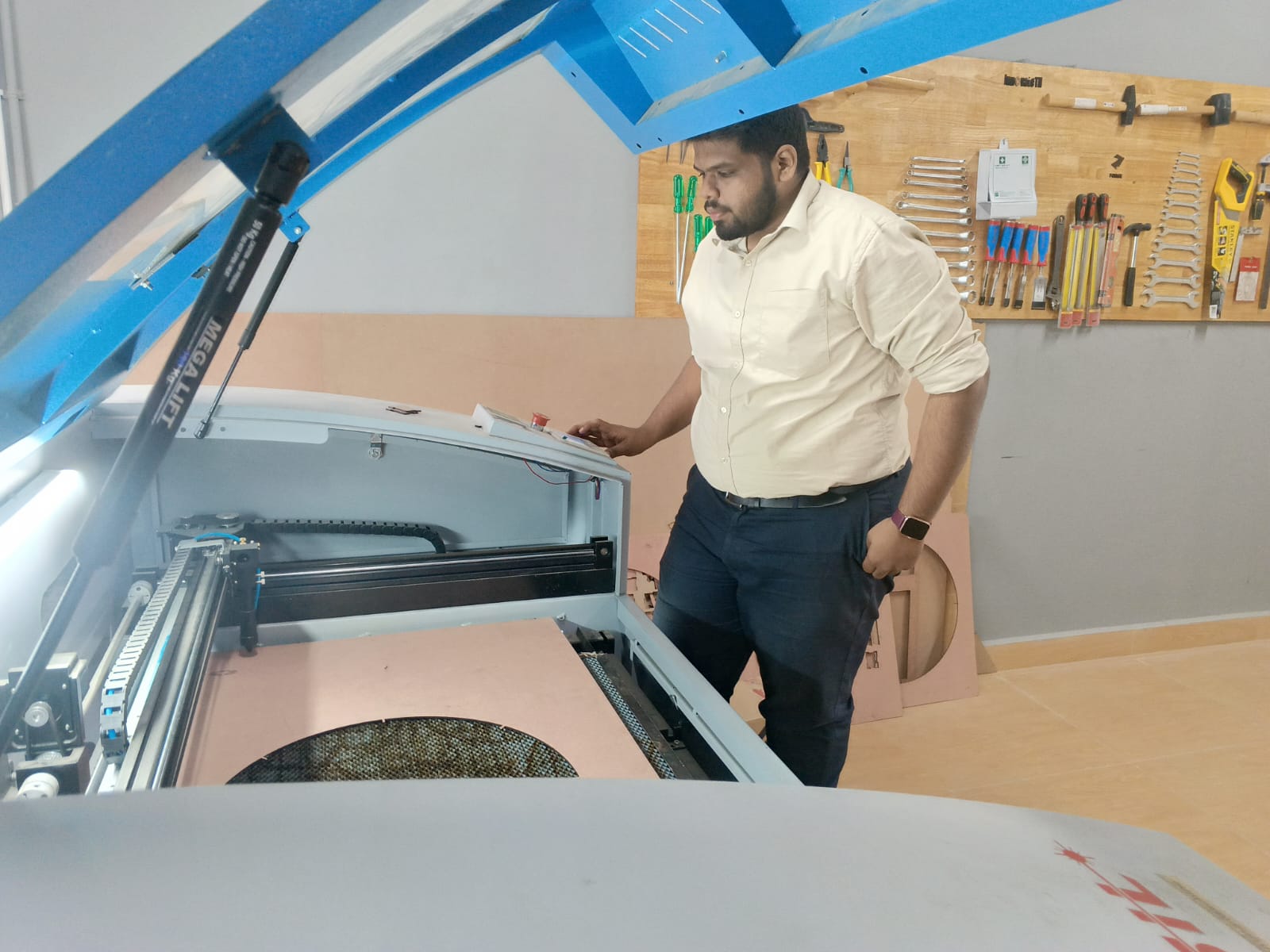
Before starting any laser cutting operation, it is important to properly prepare the machine and verify that all safety systems are functioning correctly. Although laser cutting is a highly efficient fabrication process, the concentrated laser beam can generate high temperatures, smoke, and potentially hazardous fumes if the machine is not operated correctly.
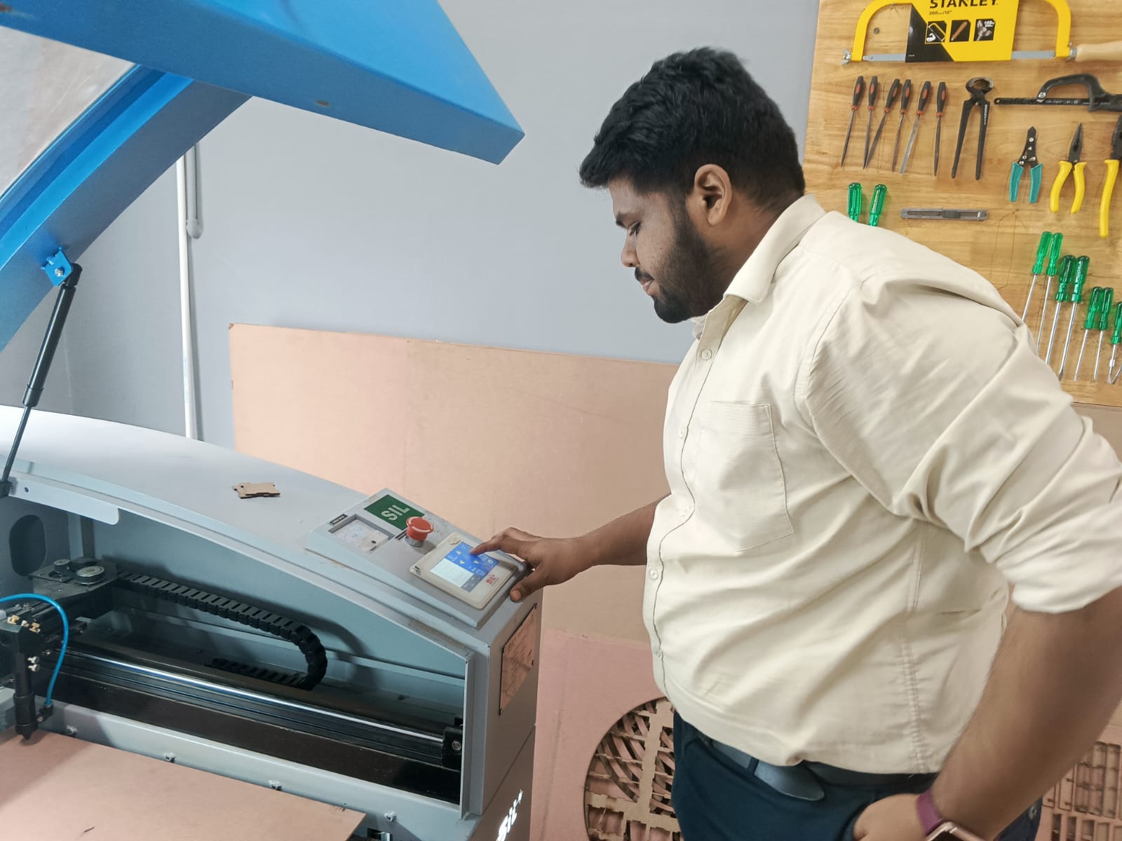
Before loading the material, I inspected the machine bed to ensure it was free from debris and leftover material from previous jobs. The material sheet was then placed flat on the honeycomb work surface to prevent movement during cutting. Proper alignment is essential because even a small shift can affect dimensional accuracy.
The laser head was positioned above the material and the focus height was adjusted using the machine's focusing tool. Maintaining the correct focal distance ensures that the laser beam remains concentrated and produces clean cuts with minimal burning along the edges.
Pre-Operation Checklist
- Verify that the cooling system is running correctly.
- Check the water level and circulation in the chiller.
- Confirm that the exhaust blower is operational.
- Ensure the air assist compressor is switched on.
- Inspect mirrors and lens for dust or contamination.
- Verify material placement and alignment.
- Check the laser focus distance.
- Confirm that emergency stop access is unobstructed.
- Review cutting parameters before execution.
Safety Precautions Followed
Laser cutters should never be left unattended during operation. Even materials that are considered safe for laser processing can ignite if incorrect power settings are used. Continuous monitoring allows immediate response in the event of excessive burning, flame formation, or machine malfunction.
- Never operate the machine without proper ventilation.
- Keep the machine enclosure closed during operation.
- Do not leave the machine unattended while cutting.
- Avoid processing unknown or hazardous materials.
- Keep a fire extinguisher accessible near the machine.
- Use only approved laser-safe materials.
- Verify cutting parameters through test cuts before production.
- Ensure proper grounding and electrical safety.
- Stop the machine immediately if unusual smoke or flames appear.
Materials to Avoid or Use with Caution
Not all materials are suitable for processing with a CO₂ laser cutter. Some materials release toxic gases, while others reflect the laser beam and may damage the optics. Certain materials can be processed using other laser technologies such as fiber lasers, but are not suitable for the CO₂ laser available in our Fab Lab.
| Material | Reason |
|---|---|
| PVC / Vinyl | Produces toxic chlorine gas and can damage machine components. |
| ABS Plastic | Produces harmful fumes and leaves sticky residue. |
| Polycarbonate | Discolors, melts excessively, and does not cut cleanly. |
| Fiberglass | Contains harmful glass fibers and resin fumes. |
| Carbon Fiber | Produces hazardous dust and conductive particles. |
| Reflective Metals (Aluminium, Copper, Brass) | Can reflect the CO₂ laser beam and damage mirrors or optics. |
| Steel and Stainless Steel | Cannot be effectively cut using standard CO₂ laser systems without specialized equipment. |
| Mirror-Finish Materials | Highly reflective surfaces may cause beam reflection and unsafe operation. |
| Unknown Materials | May release toxic gases or behave unpredictably during cutting. |
Through this exercise, I learned that material selection is as important as machine settings. While wood, MDF, cardboard, and acrylic are suitable for CO₂ laser cutting, several materials such as PVC, reflective metals, and unknown plastics must be avoided for safety reasons. I also learned that different laser technologies are used for different materials. For example, fiber laser systems are commonly used for cutting and engraving metals, whereas CO₂ lasers are better suited for non-metallic materials.
Group Assignment
For more About Group AssignmentsKerf Measurement
Procedure
Using LaserCAD software for sending the design to the Laser machine
Cutting Designed files for measurement
Measuring the Files for the Kerf Measurement in both MDF and Acrylic materials
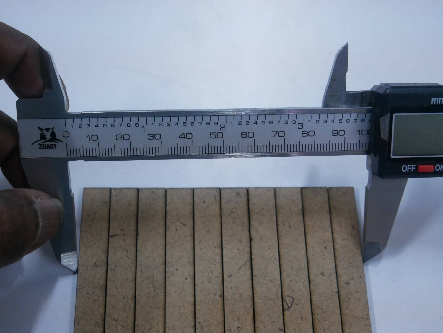
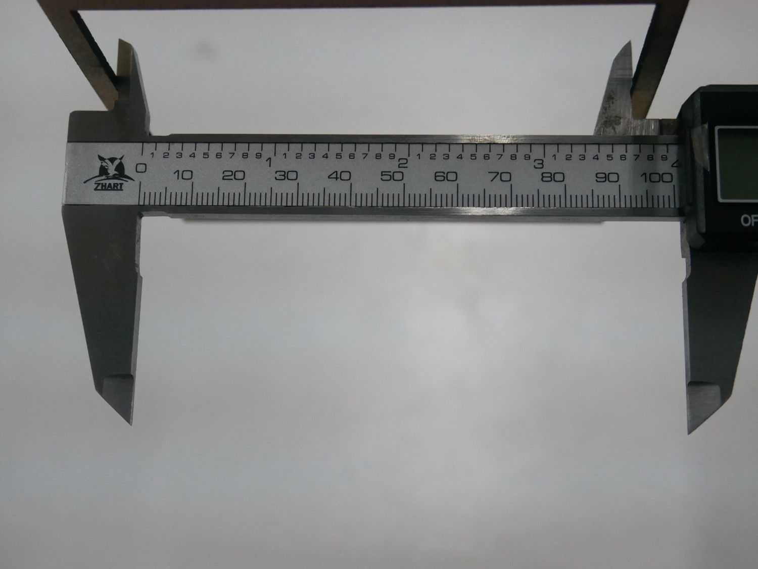
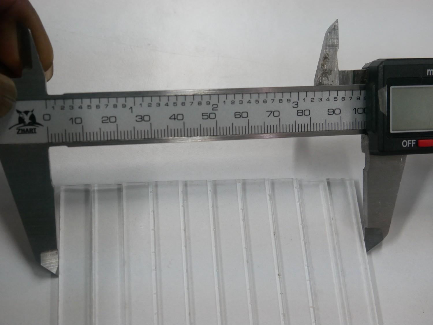
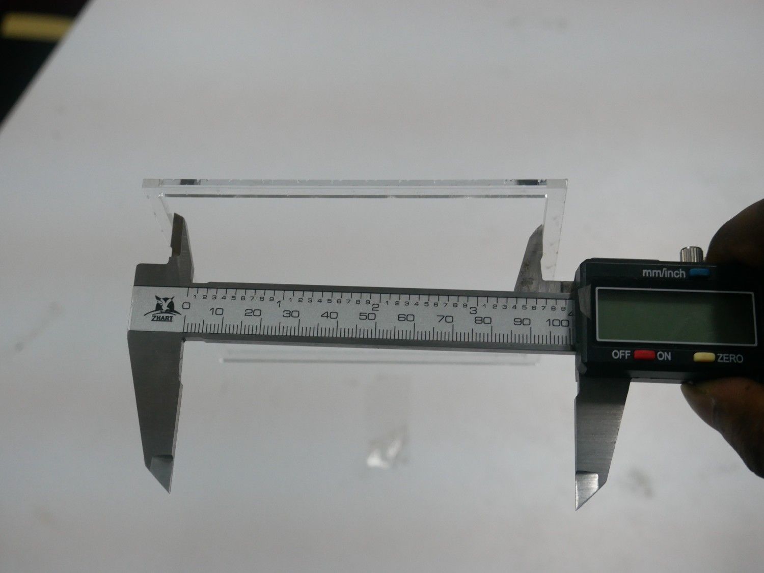
Results
| Material | Designed Size | Measured Slot (mm) | Measured Piece (mm) | Kerf (mm) |
|---|---|---|---|---|
| MDF | 100 × 100 | 100.30 | 99.70 | 0.30 |
| Acrylic | 100 × 100 | 100.25 | 99.75 | 0.25 |
Parametric Lamp Design Kit
The initial concept for the parametric lamp was inspired by the following reference video. video
2D laser-cuttable design with customizable dimensions
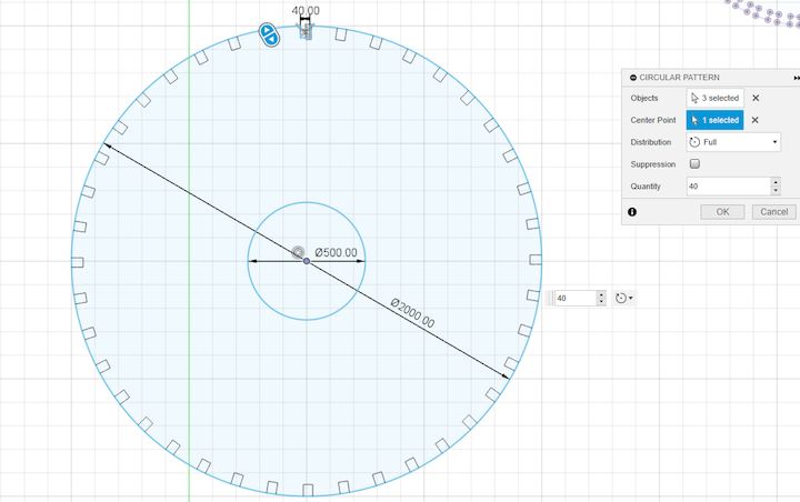
The lamp was divided into three primary components: connectors, support arms, and the base plate to simplify the design and assembly process.
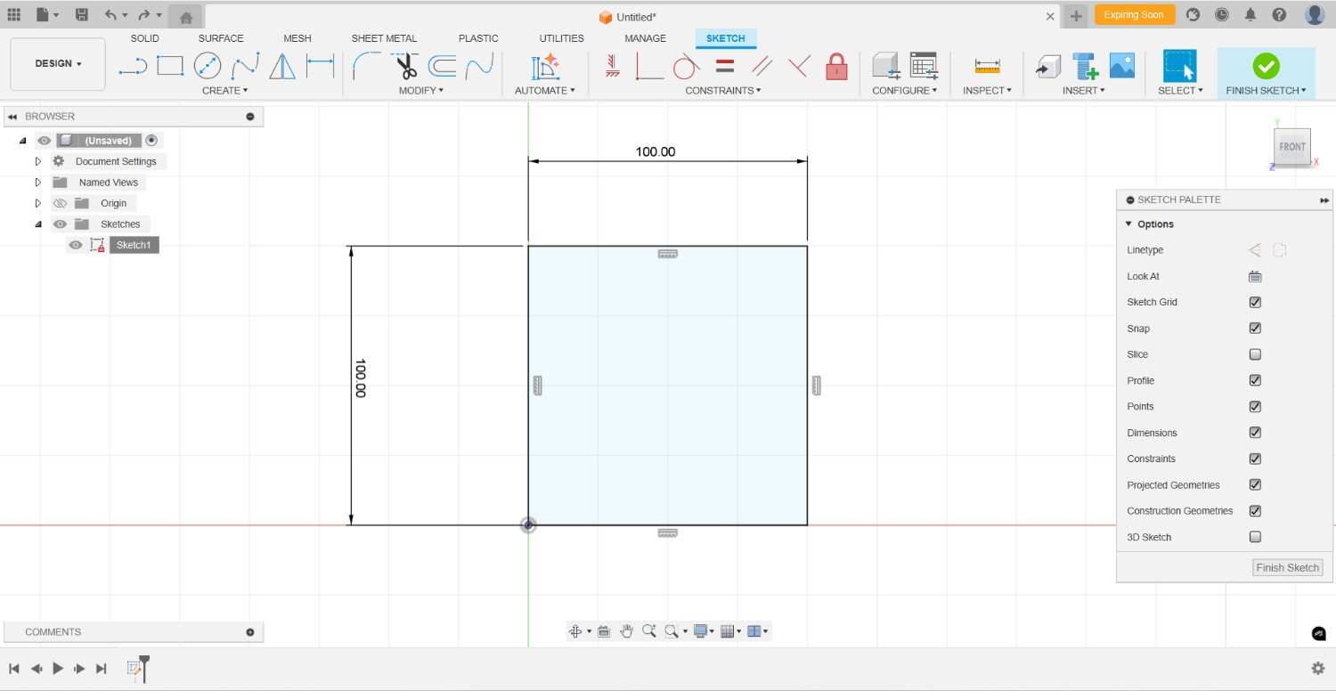
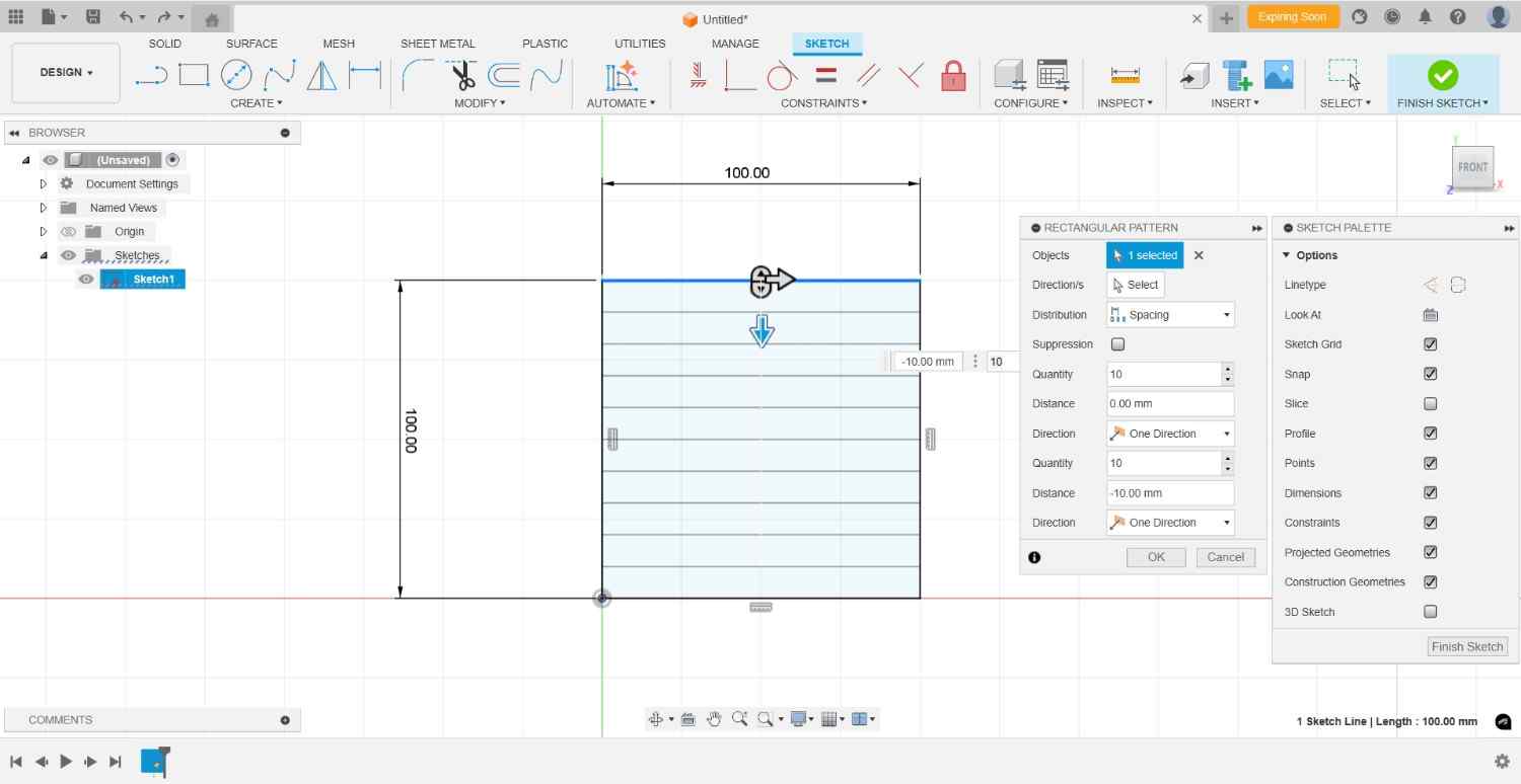
Parametric Design in Fusion 360
Parametric design in Fusion 360 involves creating models where key dimensions and parameters drive the geometry. This approach allows for easy modifications and fine-tuning, as changes to the parameters automatically update the entire model.
- Defining Parameters: Parameters are defined at the start, such as the length, width, or diameter. These parameters can be used throughout the design to maintain consistency and allow for quick adjustments.
- Using Constraints: Constraints are used to maintain relationships between different parts of the model. For example, ensuring that two lines remain parallel or that a circle stays concentric with another shape.
- Advantages: Parametric design allows for efficient iteration, as changes can be made quickly by altering parameter values. This is particularly useful for prototyping and testing different design configurations.
- Example: When designing a lamp in Fusion 360, you can set parameters for the lamp's height, base diameter, and connector thickness. Adjusting these parameters will automatically resize and redefine the lamp's components, providing flexibility in design exploration.
By leveraging parametric design, designers can create adaptable and scalable models that meet specific requirements and constraints.
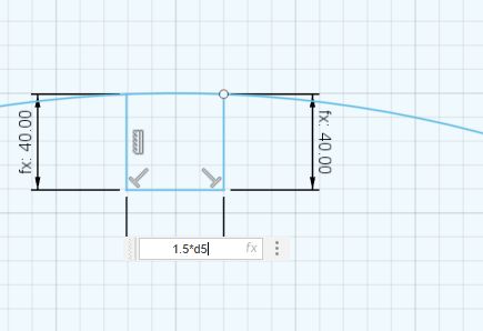
For the Parametric Design
I Initially fixed a Dimension of d5 to the common for all dimensions
The same parameter value was reused for the support arm design to maintain consistency across all mating features.
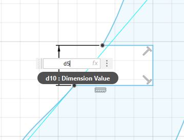
Similarly I have used this for all of my areas where I am Connecting one with Each other
Hand Design
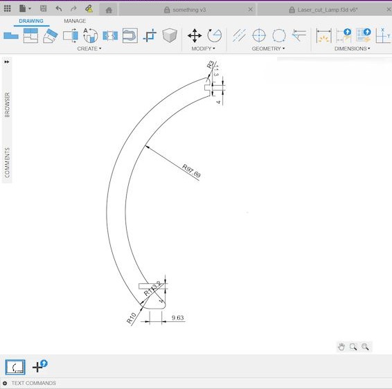
Initially I considered all the aspects and then having the edges of the connectors as 4mm and as there two connectors will be have and I assigned the 4mm as both ends as a parametric.
Base Plate Design
And then considering the common 4mm connectors as parametric constraint for the base plate cuts
As we have to connect the hands to the base plate, so I used the same parametric as the connector, which is 4mm.
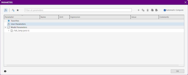
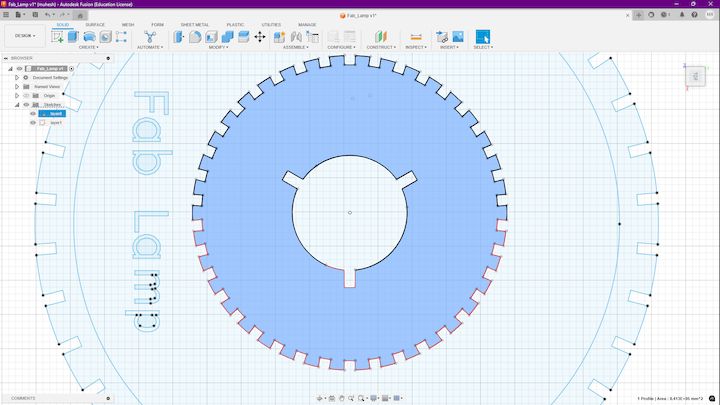
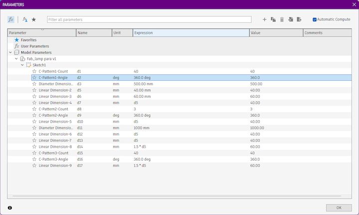
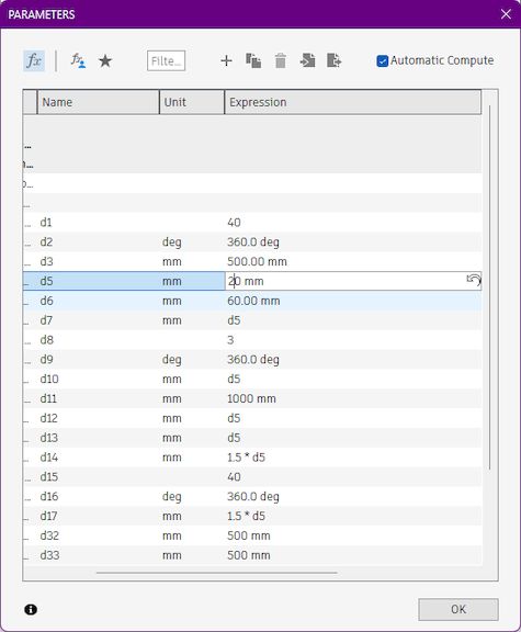
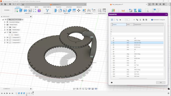
Intial parameters
I have done the initial parametric design in Fusion 360 and the below listed are the initial parameters that came along with the design
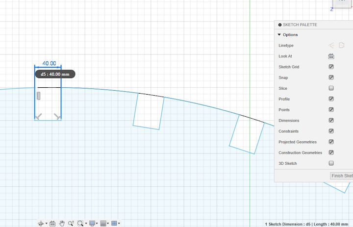
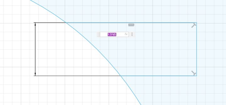
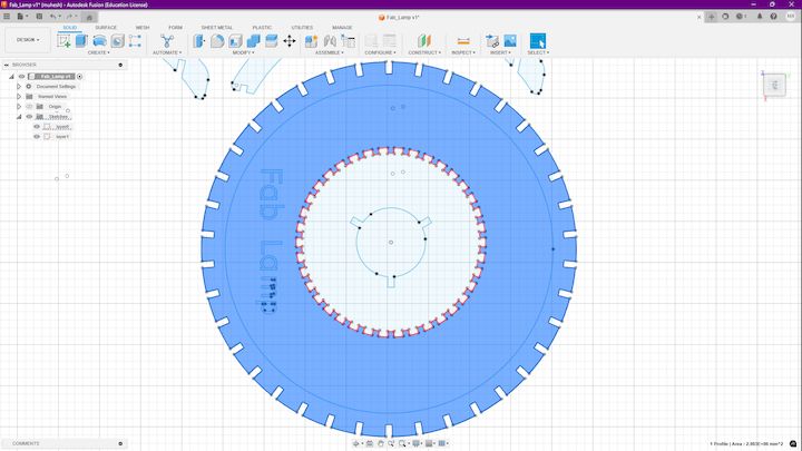
To validate the parametric model, the primary dimension was modified and the resulting geometry updates were observed.
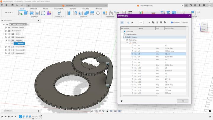
Initally you can see here the design is much more what we initially had, Now I going to change that value from 40mm to 20 mm, Let's see how its affecting the design
Hero Shot
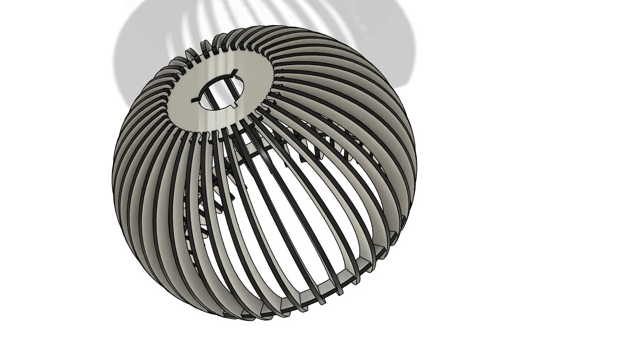
Interactive 3D Model Visualization
Before proceeding to fabrication, I exported the final parametric lamp design as an STL file and uploaded it to Sketchfab. This allows the model to be viewed interactively in a web browser, making it easier to inspect the geometry, assembly structure, and overall design from different angles. The embedded viewer below provides a complete 3D representation of the lamp design developed during this assignment.
The Sketchfab viewer provides an interactive way to evaluate the final design before manufacturing. It also serves as a useful documentation tool by allowing reviewers to inspect the model geometry without requiring CAD software.
LaserCAD
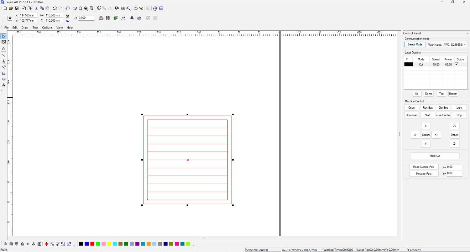
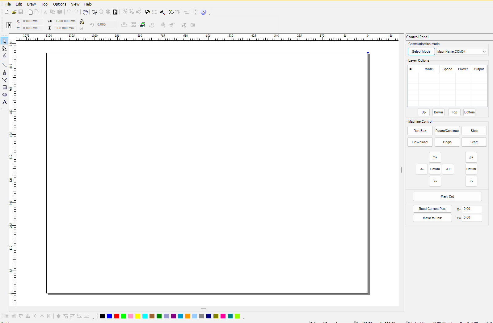
LaserCAD Software Interface
LaserCAD is the software used to prepare, optimize, and control laser cutting operations. It provides an intuitive interface for importing vector designs, assigning cutting parameters, configuring layers, and communicating directly with the laser cutter. The software supports various file formats including DXF, AI, PLT, BMP, and other vector-based design files commonly used in digital fabrication workflows.
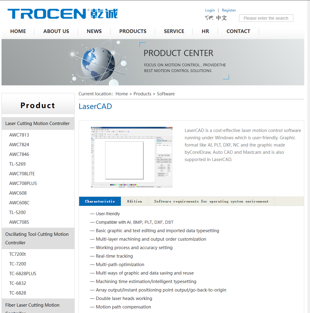
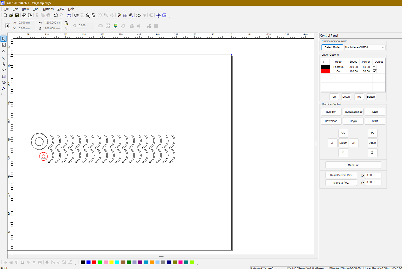
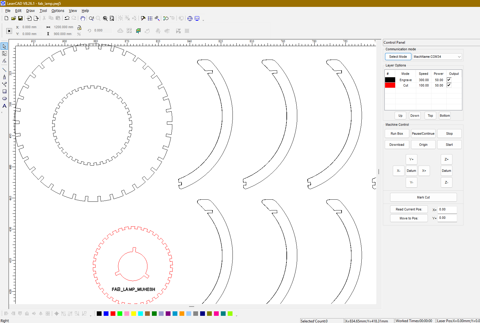
The screenshot below shows the LaserCAD workspace used during this assignment. The software allows users to import designs, arrange parts within the working area, assign cutting layers, configure speed and power settings, preview toolpaths, and transfer jobs directly to the laser cutting machine. These features make LaserCAD an essential part of the digital fabrication workflow.
LaserCAD serves as the bridge between a CAD design and the laser cutting machine. While creating a design in Fusion 360 is an important first step, the design itself cannot be interpreted directly by the laser cutter. This is where LaserCAD becomes essential. It converts design geometry into machine-readable instructions and provides complete control over cutting parameters, processing order, material positioning, and machine communication.
LaserCAD Workflow
Step 1: Opening LaserCAD
The first step was launching LaserCAD and creating a new workspace for the laser cutting job.
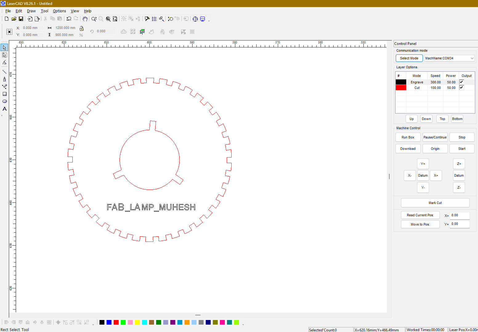
Step 2: Importing the DXF File
The DXF file exported from Fusion 360 was imported into LaserCAD. After importing, all profiles were verified to ensure there were no open contours or duplicate entities.
Step 3: Layer Configuration
One of the most useful features of LaserCAD is its layer management system. Different operations such as cutting, engraving, and marking can be assigned to separate layers.
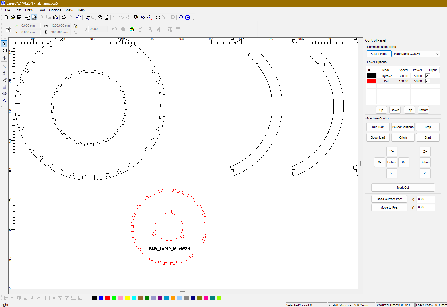
Step 4: Setting Speed and Power Parameters
The cutting parameters were adjusted according to the material thickness. Proper selection of power and speed ensures clean cuts while minimizing burning or incomplete cuts.
Step 5: Sending the Job to the Laser Cutter
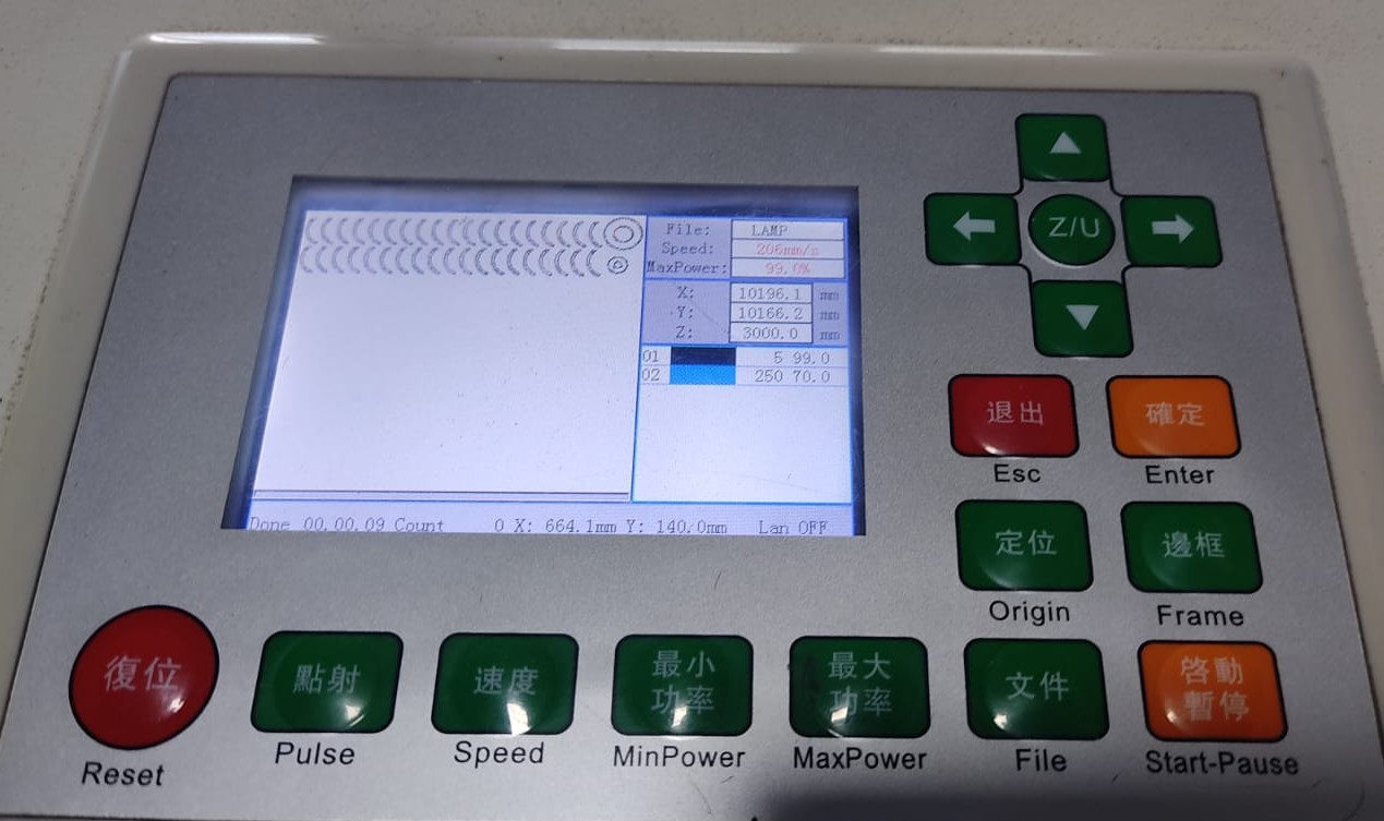
After confirming all settings, the file was transferred to the machine controller. The laser was focused, the origin was set, and the cutting process was started.
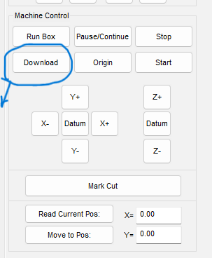
These are the final alignment settings sent to the laser cutter
Key LaserCAD Features Used
- Importing DXF files from Fusion 360
- Layer-based operation management
- Laser power and speed configuration
- Material positioning and nesting
- Frame preview and job verification
- Toolpath visualization
- Machine communication and control
- Real-time job monitoring
What I Learned from LaserCAD
Working with LaserCAD helped me understand how digital designs are transformed into physical objects. More importantly, it taught me that successful laser cutting is not just about drawing a design. Material properties, kerf compensation, speed settings, laser power, and machine setup all play a major role in achieving accurate results. The experience helped me understand the complete workflow of digital fabrication, from design preparation to final manufacturing.
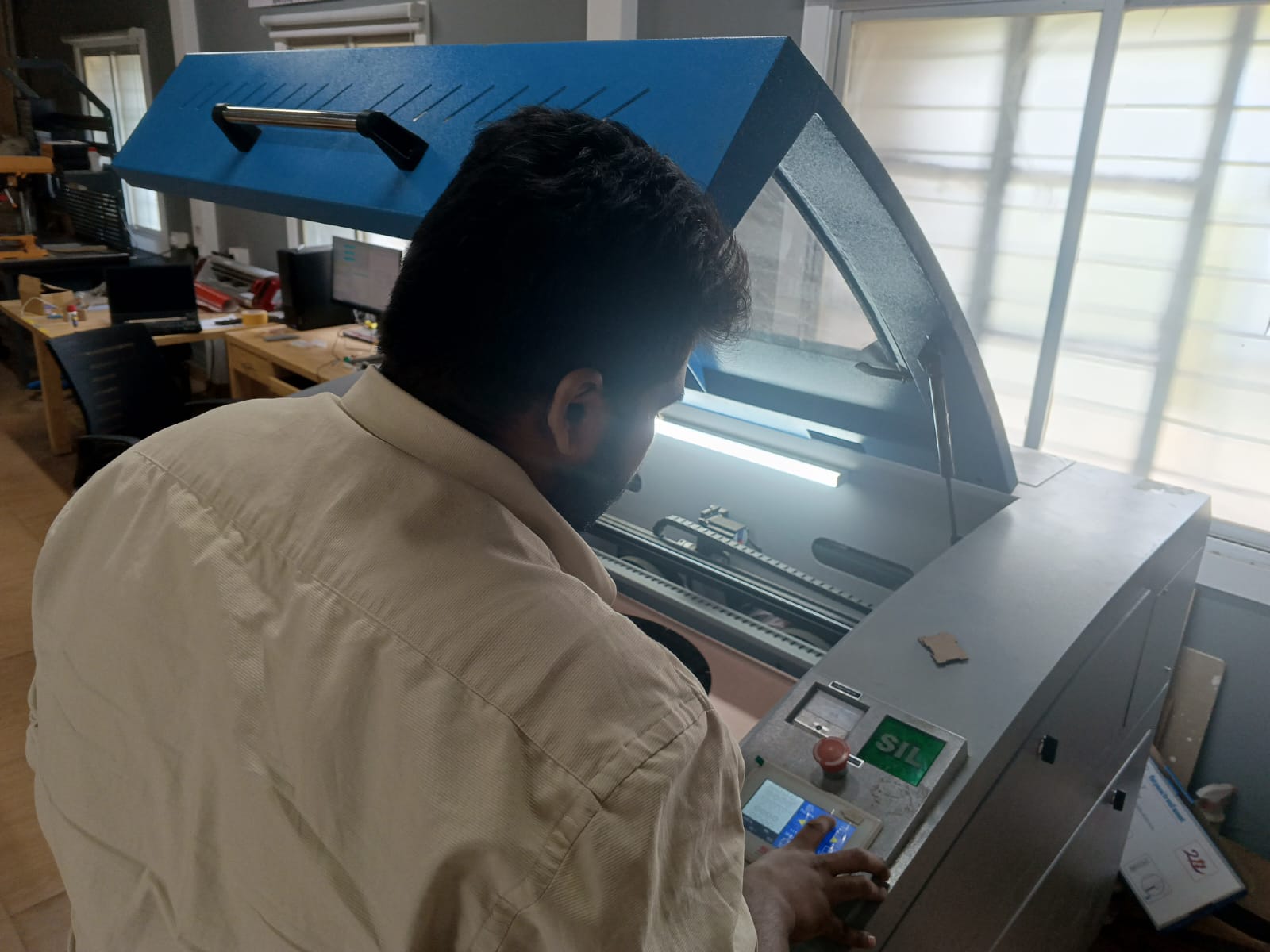
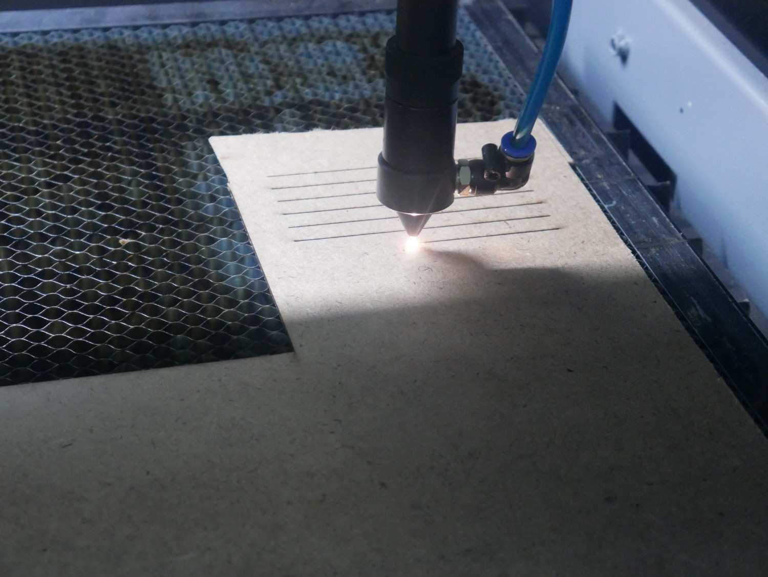
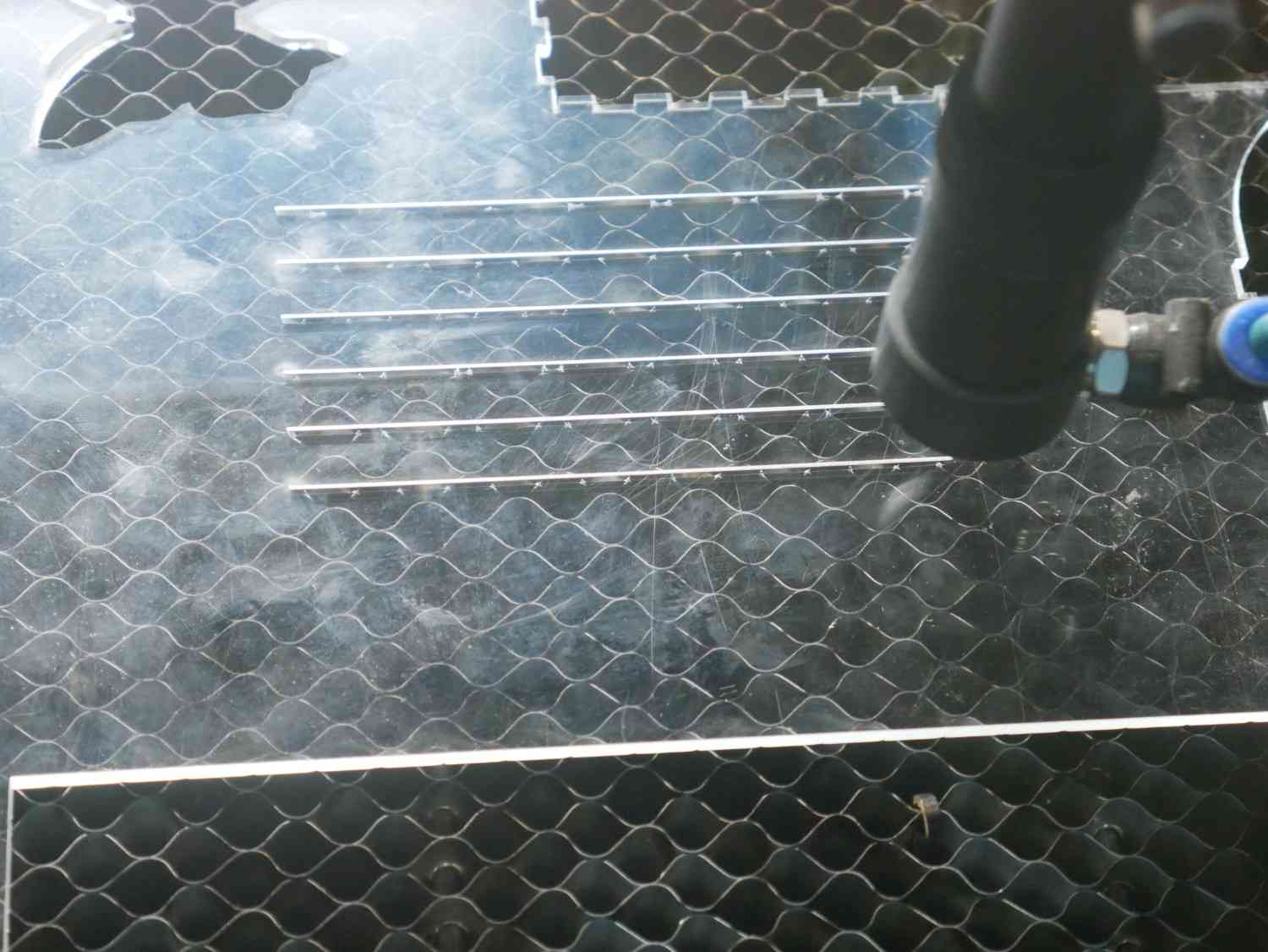
Cutting Process
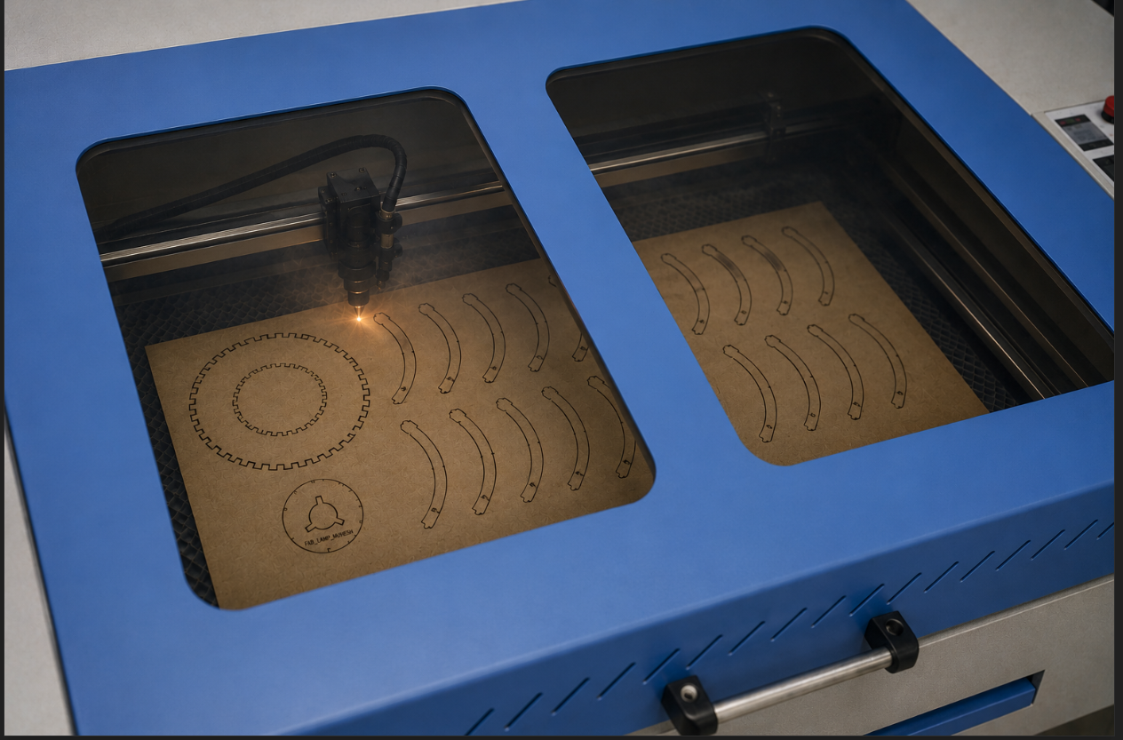
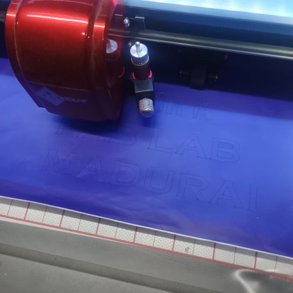
Figure 4: Real-time laser cutting operation in progress. The laser head follows the imported vector paths and precisely cuts the MDF sheet according to the generated design. Continuous monitoring was performed to ensure accurate cutting, proper material alignment, and safe machine operation throughout the fabrication process.
After verifying the machine settings and loading the design file, the cutting process was initiated. The laser beam accurately followed the programmed toolpath, producing clean and precise cuts on the MDF sheet. During operation, I monitored the cutting progress through the machine's viewing window to ensure proper focus, consistent cutting quality, and to prevent any material shifting or excessive burning. The completed components were then removed from the cutting bed and prepared for assembly.
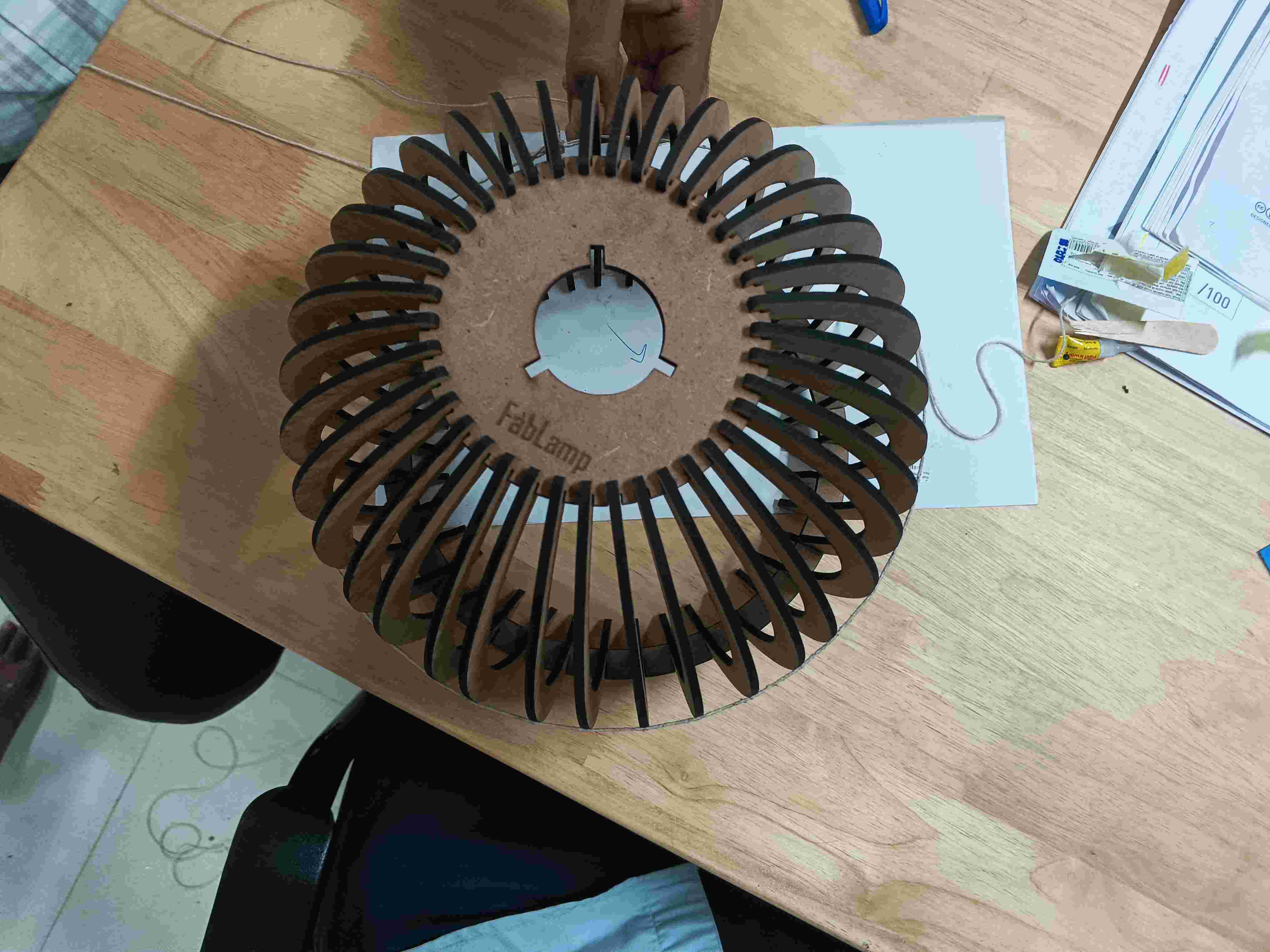
Parametric Lamp Assembly
After completing the laser cutting process and verifying the dimensions in LaserCAD, I proceeded with the physical assembly of the parametric lamp. The design consists of multiple laser-cut MDF ribs that interlock between the top and bottom circular rings. The assembly process helped me understand the importance of kerf compensation, slot tolerances, and precision in digital fabrication.
The laser-cut parts were removed carefully from the material sheet and inspected for dimensional accuracy. Each rib was then inserted sequentially into the slots provided on the bottom ring. The top ring was later aligned with the corresponding slots to complete the three-dimensional structure. Due to the parametric design approach, all parts fit together without the need for adhesives or additional fasteners.
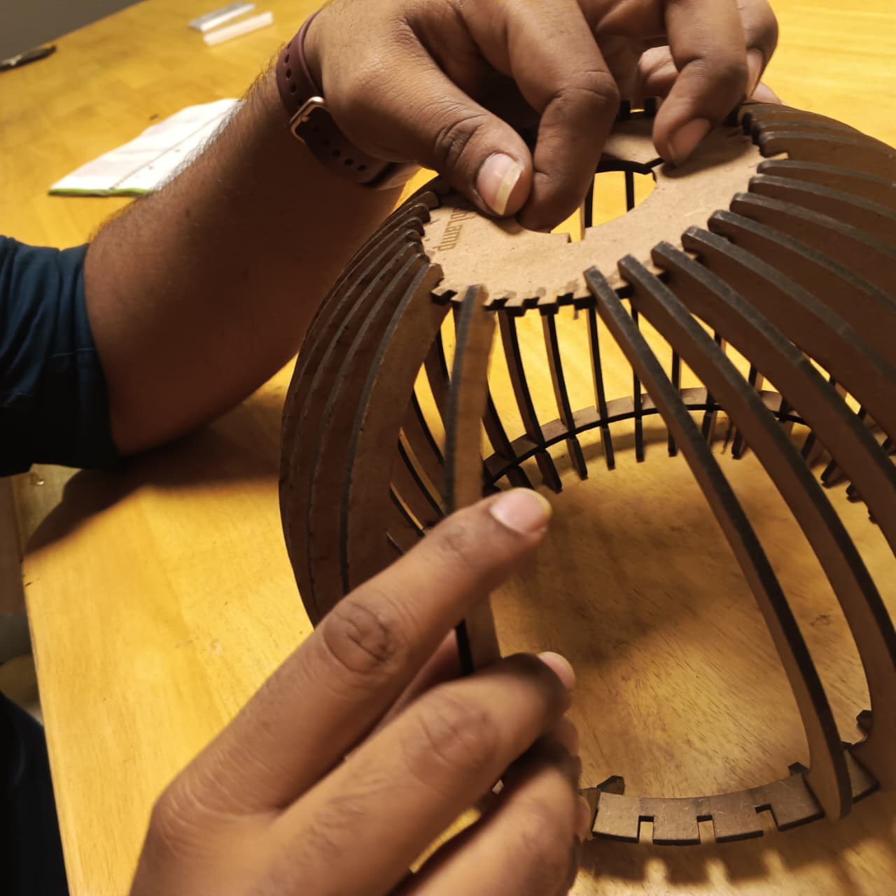
Figure 1: Inserting individual ribs into the top ring during assembly.
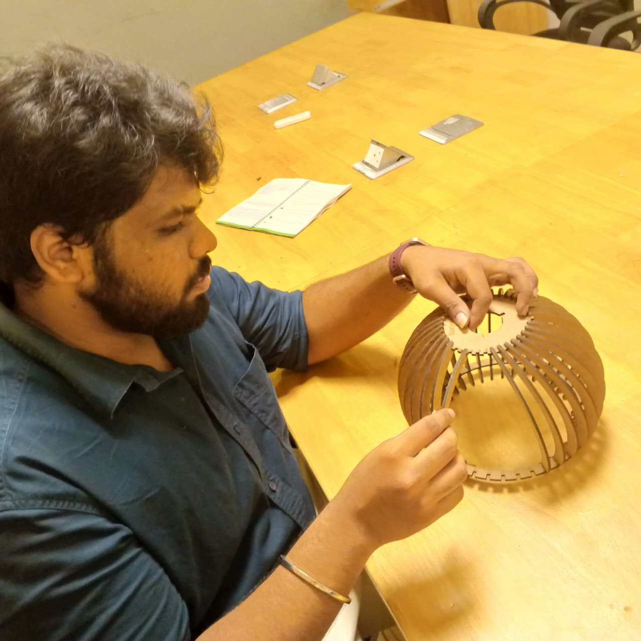
Figure 2: Completed assembly of the parametric lamp structure.
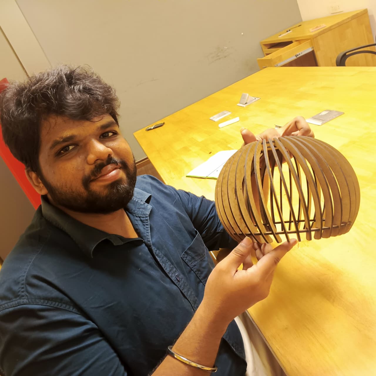
Figure 3: Final alignment and fitting verification of the laser-cut components.
Observations During Assembly
- The laser-cut slots provided a snug fit without requiring glue.
- Kerf compensation played a major role in achieving proper interlocking.
- The parametric design allowed easy modification of dimensions before fabrication.
- The assembly process demonstrated how 2D laser-cut components can form complex 3D structures.
- The final lamp structure was rigid, lightweight, and aesthetically pleasing.
Key Learnings
This activity reinforced the relationship between CAD design and physical fabrication. Even small dimensional errors can affect the assembly process significantly. Through this exercise, I gained practical experience in designing parametric models, preparing files in LaserCAD, understanding kerf effects, and assembling a functional product using computer-controlled cutting techniques.
Vinyl Cutting
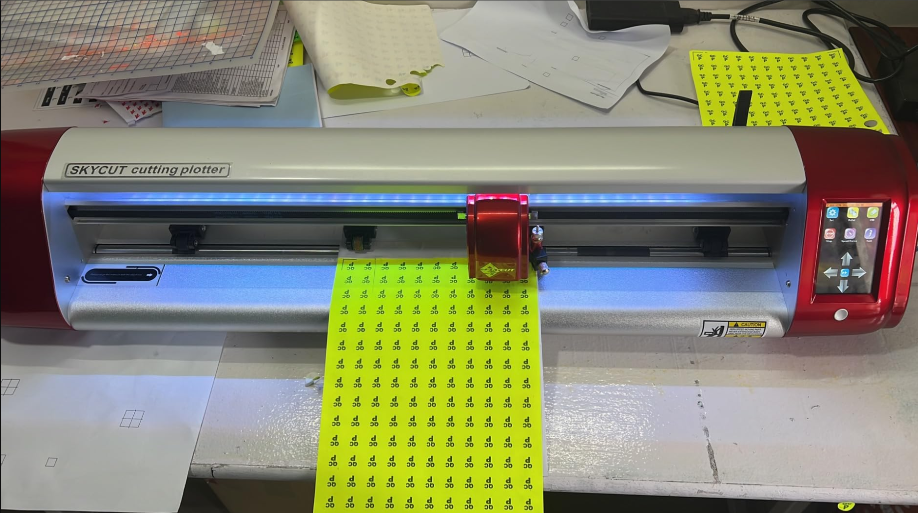
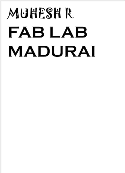
For this week's computer-controlled cutting assignment, I made a personalized vinyl sticker with my name "MUHESH | FAB LAB MADURAI". The goal was to understand the full workflow of designing, preparing, cutting, and transferring vinyl using a SkyCut C24 machine along with the SignMaster software suite, which includes the Vinyl Spooler, where the actual cutting job is processed.
This documentation explains each step in detail, from digital design to final application.
SkyCut C24 Vinyl Cutting Machine
For the vinyl cutting assignment, I used the SkyCut C24 Vinyl Cutter, a computer-controlled cutting machine designed for processing self-adhesive vinyl sheets, heat transfer vinyl, sticker materials, and other thin flexible media. Unlike laser cutters that remove material using thermal energy, vinyl cutters use a precision blade to follow vector paths and cut the material without damaging the backing sheet.
The SkyCut C24 receives vector-based cutting instructions directly from SignMaster software. The machine moves the vinyl sheet along the Y-axis while the blade carriage moves along the X-axis, allowing accurate reproduction of text, logos, graphics, and custom sticker designs.
Machine Specifications
| Parameter | Specification |
|---|---|
| Machine Model | SkyCut C24 |
| Machine Type | Vinyl Cutting Plotter |
| Maximum Media Width | 630 mm |
| Maximum Cutting Width | Approximately 600 mm |
| Cutting Method | Drag Knife Blade |
| Blade Type | 45° / 60° Carbide Blade |
| Connection | USB Interface |
| Supported Software | SignMaster, Vinyl Spooler |
| Supported Formats | SVG, DXF, AI, EPS, PLT |
| Typical Materials | Adhesive Vinyl, HTV, Sticker Sheets, Reflective Vinyl |
| Applications | Sticker Making, Signage, Labels, Decals, Graphics |
The machine is widely used in signage industries because it can accurately cut complex vector designs while maintaining clean edges and excellent repeatability. During this assignment, it was used to manufacture a custom vinyl sticker by following vector paths generated in SignMaster software.
Design Process
Choosing the Design Software
- I used a vector-based design tool (Inkscape / Illustrator / CorelDRAW)
- Vinyl cutters require vector paths, so the design must be created using scalable vector graphics
Creating Text for the Sticker
- I created the following text:
- MUHESH
- FAB LAB MADURAI
- I used a bold, easy-to-weed font to ensure smooth cutting and clean readability
Converting Text to Vector Paths
Since vinyl cutters cannot interpret text formats:
- I converted the text to paths/outlines/curves
- This prevents font errors and ensures clean blade tracing
Final Design Dimensions
- I scaled the design to the desired size:
- Width: ~14.93 cm
- Height: ~8.3 cm
- This ensures easy weeding and efficient material usage
Exporting the File
- To prepare the file for cutting, I exported it as:
- SVG (recommended)
- The SVG file was then imported into SignMaster
SignMaster Software
SignMaster is the design and machine control software used to prepare vinyl cutting jobs for the SkyCut C24 cutter. The software provides a complete workflow for creating vector graphics, editing text, importing SVG files, configuring machine parameters, and sending jobs directly to the cutter.
Think of SignMaster as the bridge between the design and the machine. While the vinyl cutter performs the physical cutting operation, SignMaster is responsible for generating the cutting paths, arranging artwork, setting dimensions, and communicating with the cutter through Vinyl Spooler.
Main Features of SignMaster
- Vector drawing and editing tools
- Text creation and font management
- SVG, DXF and AI file import
- Shape generation tools
- Contour cutting support
- Machine parameter configuration
- Cut preview and simulation
- Direct communication with vinyl cutters
Software Interface Overview
The SignMaster interface consists of several toolbars and menus that simplify the design workflow. The File menu is used for importing and exporting files, while the drawing toolbar provides tools for creating shapes, curves, text, and custom vector graphics.
The software also provides zoom tools, page layout controls, drawing utilities, and font management features. These tools allow users to quickly prepare designs before sending them to the vinyl cutter.
Workflow Followed in SignMaster
- Create or import a vector design.
- Verify dimensions and scale.
- Adjust artwork placement.
- Select the SkyCut C24 cutter.
- Configure blade force and cutting speed.
- Preview the cutting path.
- Send the job to Vinyl Spooler.
- Transfer the cutting job to the machine.
One of the most useful features of SignMaster is the Vinyl Spooler utility. It provides a live preview of the cutting job, machine settings, material dimensions, blade parameters, and communication status before the final cut is executed.
Sign Master is a software used to create and customize vinyl cutting designs. It is a free software that can be downloaded online. This software allows the user to create their own designs or modify existing ones. It also provides a variety of tools and features to help the user to create their design.
- Create and customize vinyl cutting designs
- Modify existing designs
- Provides a variety of tools and features
SignMaster Software
SignMaster is the software used to design, edit, and prepare artwork for vinyl cutting. It acts as the communication bridge between the computer and the SkyCut C24 vinyl cutter. The software provides tools for creating vector graphics, managing text, importing external designs, configuring cutter parameters, and sending jobs directly to the machine.
For this assignment, I used SignMaster to create and prepare the vinyl sticker before sending it to the SkyCut C24 cutter. The following screenshots show the workflow and important features explored during the process.
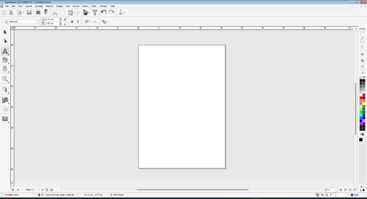
1. SignMaster Workspace
The SignMaster workspace provides the main drawing area where designs are created and edited. The workspace includes rulers, toolbars, alignment guides, color palettes, and object management tools.
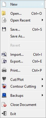
2. File Menu Options
The File menu contains options for creating new projects, opening existing files, importing SVG artwork, exporting designs, and sending jobs to the cutter.
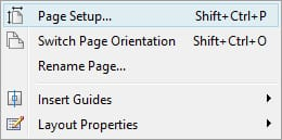
3. Page Setup and Layout Configuration
Before starting a design, the page size and orientation can be configured. This ensures that the artwork dimensions match the actual vinyl material loaded into the machine.
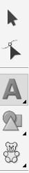
4. Drawing and Editing Tools
SignMaster provides a collection of vector drawing tools including pen tools, line tools, curves, and polylines. These tools are used to create custom artwork directly inside the software.
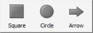
5. Shape Creation Tools
Basic geometric shapes such as squares, circles, and arrows can be quickly inserted into the design. These tools are useful when creating logos, symbols, or decorative elements.
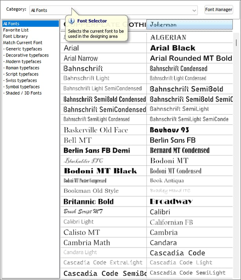
6. Font Management and Text Design
The font manager allows users to browse and select fonts for vinyl lettering applications. Since my assignment involved creating a name sticker, the font selection feature was particularly useful for testing different text styles.
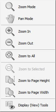
7. View and Zoom Controls
The zoom tools help inspect artwork in detail before cutting. Features such as Zoom In, Zoom Out, Zoom to All, and Pan Mode simplify design verification and editing.
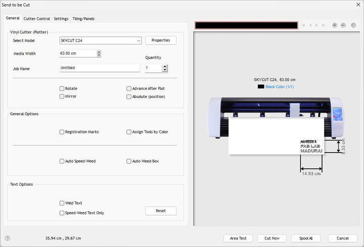
8. Sending the Design to the Cutter
Once the design is finalized, the Send to Cutter option is used to prepare the cutting job. Here the machine model, media width, and positioning parameters are configured.
9. Vinyl Spooler Interface
Vinyl Spooler manages communication between SignMaster and the SkyCut C24 cutter. It displays the job queue, cutter status, preview window, and cutting progress.
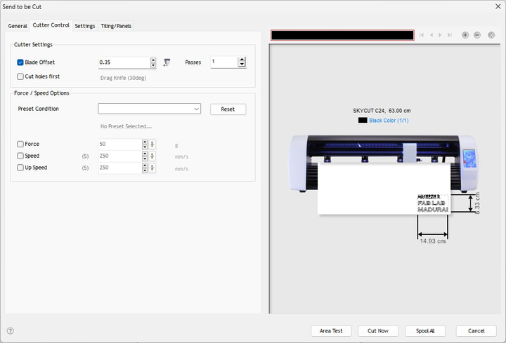
10. Cutter Control Settings
The Cutter Control tab allows adjustment of blade offset, cutting force, speed, and number of passes. These settings are important because different vinyl materials require different cutting parameters.
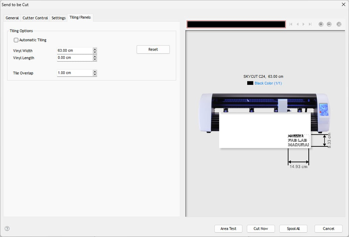
11. Tiling and Material Settings
For larger graphics, SignMaster provides tiling options that split a design into multiple sections. Material width and overlap values can also be configured from this menu.
Learning Outcome
Working with SignMaster helped me understand the complete workflow involved in vinyl cutting. I learned how vector graphics are prepared, how machine parameters influence cutting quality, and how software communicates with a computer-controlled cutter. The experience also highlighted the importance of proper artwork preparation, material setup, and cutter configuration before executing a cutting job.
Loading Vinyl into the SkyCut C24
Aligning and Securing the Material
Steps:
- Lifted pinch rollers
- Inserted vinyl sheet
- Aligned it parallel to the machine guide
- Positioned pinch rollers over the grit wheels
- Locked them in place
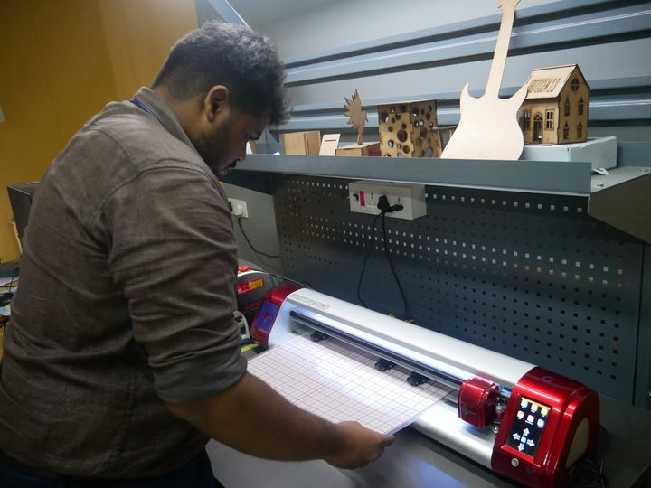
Proper alignment prevents shifting during cutting.
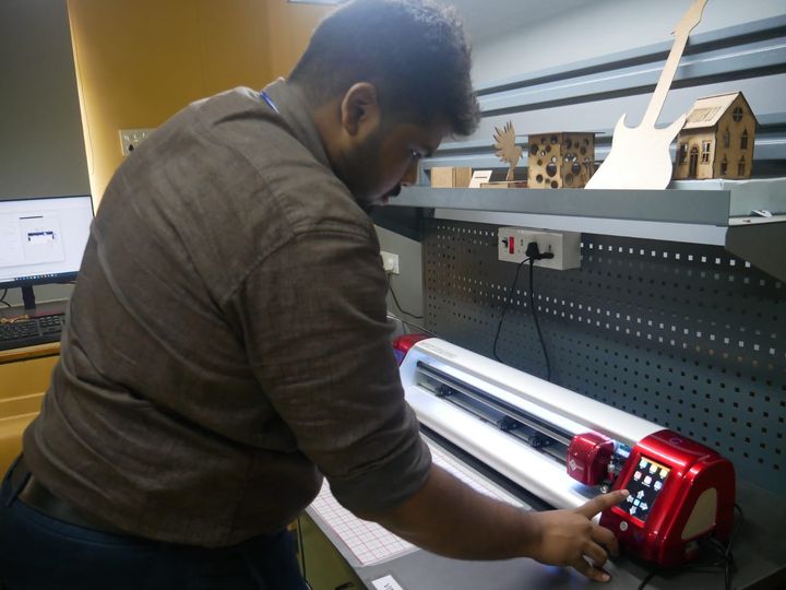
Setting the Origin
- Using the machine controls, I positioned the blade at the lower-left corner and pressed:
- Set Origin
- This tells the machine exactly where to start cutting
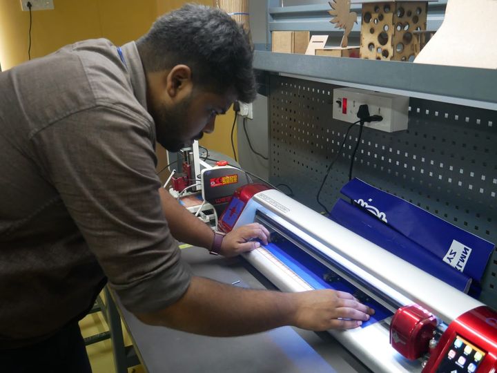
Cutting the Vinyl
Executing the Cutting Job
- Back in Vinyl Spooler, I clicked Cut Now
- The SkyCut C24 began cutting the sticker precisely following the vector paths
- During the process, I monitored:
- Material feed
- Blade movement
- Any lifting or tearing
Weeding the Vinyl
Removing Excess Vinyl
- Using a weeding tool or tweezer:
- I peeled away the unwanted outer vinyl
- Removed internal pieces inside letters (A, R, B, D, etc.)
- Weeding requires patience, especially for small text
Inspecting the Results
After weeding, I checked:
- Cleanly cut edges
- No tears
- All letters intact
- Proper spacing maintained
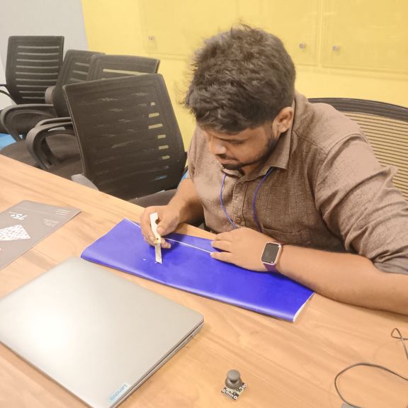
Applying Transfer Tape
Preparing the Tape
- I cut a transfer tape piece slightly larger than the sticker
Applying the Tape Over the Vinyl
Steps:
- Placed tape over the weeded design
- Pressed it firmly using a squeegee
- Ensured bubble-free adhesion
The tape helps lift the design cleanly for application.
Lifting the Sticker
- I slowly peeled the tape, ensuring the vinyl letters stuck to it completely
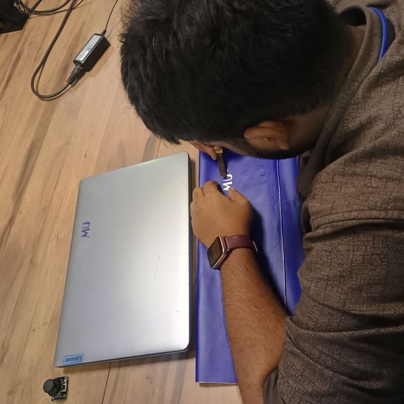
Applying the Final Sticker
Preparing the Target Surface
- I cleaned the surface using a dry cloth and ensured it was dust-free
Transferring the Vinyl
Steps:
- Placed the tape (with vinyl) on the target surface
- Reseated it with a squeegee
- Slowly peeled away the transfer tape
- The vinyl lettering remained cleanly on the surface, forming the final sticker
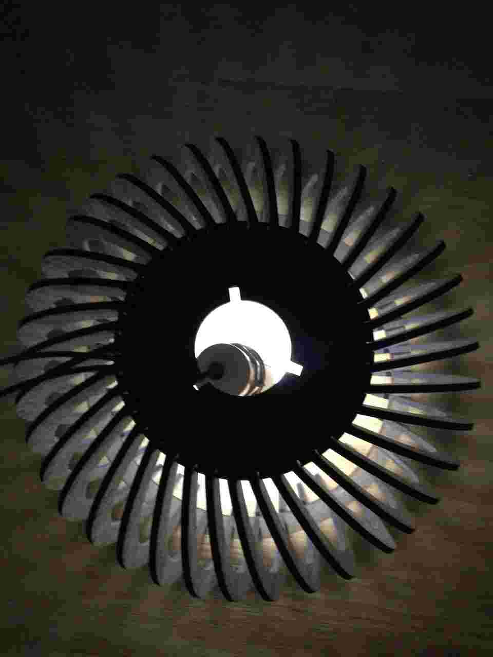
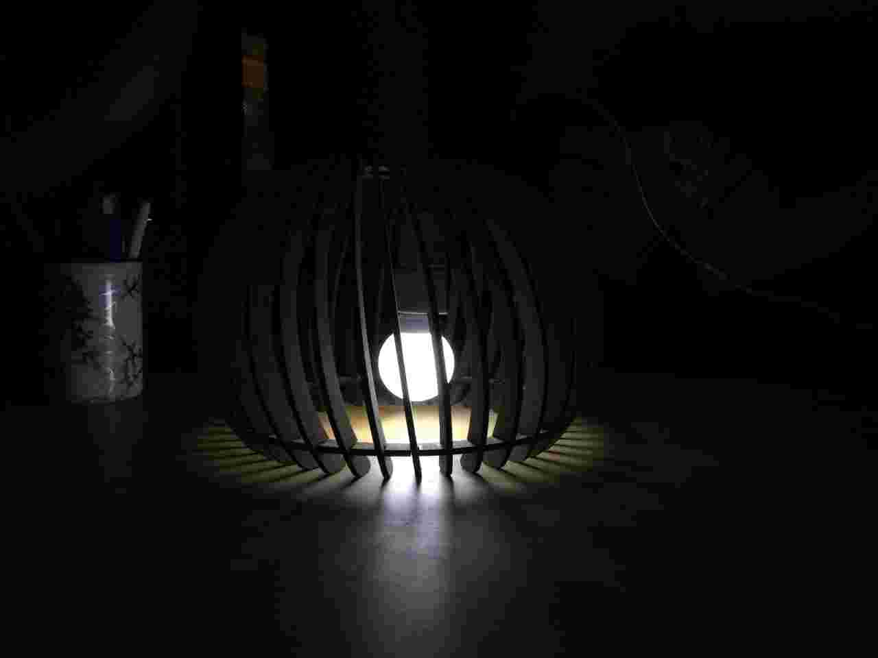
Hero Shots
After successfully assembling the parametric lamp, I installed a light source inside the structure to evaluate its visual appearance and lighting effect. The final design demonstrates how laser-cut flat components can be transformed into an aesthetically pleasing three-dimensional product through parametric design principles. The gaps between the ribs create unique shadow patterns and allow light to diffuse evenly, producing an attractive ambient lighting effect.


Download the Files
You can download the encoded model by clicking on the following links.