- Week 1 : Project Management
- Week 2 : Computer-aided
- Week 3 : Computer Controlled Cutting
- Week 4 : Embedded Programming
- Week 5 :3D Scanning and Printing
- Week 6 : Electronic Design
- Week 7 : Computer Controlled Machining
- Week 8 : Electronics Production
- Week 9 : Input Devices
- Week 10 : Output Devices
- Week 11 : Networking and Communication
- Week 12 : Mechanical Design and Machine Design
- Week 13 : Midterm Review
- Week 14 : Molding and Casting
- Week 15 : Interface and Application Programming
- Week 16 : System Integeration
- Week 17 : Wildcard Week
- Week 18 : Applications and Implications, Project Development
- Week 19 : Invention, Intellectual property and Income
- Week 20 : FInal Project Requirements
Week 17 : Wildcard Week
Objectives of the Week
Wildcard Week: Exploring Metal Laser Cutting
For Wildcard Week, I explored metal laser cutting using CAM tools, aiming to learn how digital designs are transformed into precise metal parts. This involved creating CAD models, generating CAM toolpaths, and executing the cutting process on a metal laser cutter. I gained valuable hands-on experience with machine setup, material-specific parameters, and safety protocols, all while understanding the potential and limitations of high-precision metal fabrication.
What is CAM?
Computer-Aided Manufacturing (CAM) automates the production process using software and computer-controlled machines like CNCs, laser cutters, and 3D printers. It converts CAD models into toolpaths and machine instructions, allowing for high accuracy, repeatability, and complex geometries. CAM is essential in industries like automotive, aerospace, and electronics for both prototyping and production.
Introduction to Metal Laser Cutting
Metal laser cutting uses a high-powered laser to precisely cut materials such as steel, aluminum, or brass. It is a non-contact, computer-controlled process that delivers clean edges, supports intricate patterns, and minimizes waste. Common in fabrication, automotive, and aerospace, this method is ideal for both custom and mass manufacturing.
Why Metal Laser Cutting?
Metal laser cutting was selected as the wildcard process because it introduces a manufacturing workflow that is not covered in other Fab Academy assignments. Unlike wood CNC machining, PCB milling, or 3D printing, metal laser cutting uses a high-energy laser beam to process metallic materials with high precision. This week provided an opportunity to understand industrial-scale digital fabrication and explore how CAD designs can be transformed into finished metal components.
Type of Metal Laser Cutter
| Type | How It Works | Best For | Limitations | Power Range |
|---|---|---|---|---|
| CO2 Laser Cutters | Uses a gas mixture (mostly CO2) excited by electrical discharge to generate laser. | Non-metal materials (wood, acrylic); thin metals with coatings. | Less efficient with reflective and thick metals. | Up to 1–3 kW |
| Fiber Laser Cutters | Solid-state laser transmitted through fiber optic cables. | Reflective metals like aluminum, copper, brass, stainless steel. | Higher initial cost; may need protection from back-reflections. | 500 W to 20+ kW |
| Crystal Laser Cutters (Nd:YAG / Nd:YVO4) | Uses neodymium-doped crystals as laser medium. | High-precision tasks in electronics, medical device industries. | Shorter lifespan, higher maintenance. | 100 W to several kW |
| Hybrid Laser Cutters | Combines laser cutting with other processes (e.g., punching, plasma). | Multipurpose manufacturing environments. | Complex systems; higher maintenance and upfront costs. | 1–6 kW (varies by system) |
| High-Power Laser Cutters | Uses high-power fiber or CO2 lasers for thick metal cutting. | Industrial-scale cutting (automotive, aerospace, shipbuilding). | Very high cost, large size, complex infrastructure needs. | 10–30+ kW |
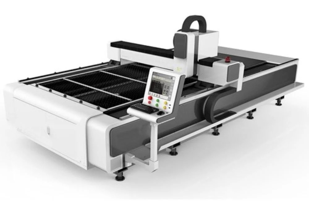
WILA 3015 CNC Metal Laser Cutting Machine
The WILA 3015 from WILA CNC Machine Tools Inc. is a high-performance CNC fiber laser cutting machine engineered for precision and productivity. Featuring a large cutting bed (typically 3000 mm x 1500 mm), it accommodates a variety of metal materials, making it ideal for industrial, custom fabrication, and educational use. The machine integrates efficiently with CAM software, enabling users to transform digital CAD models into clean, accurate, and repeatable cuts.
Advantages of the WILA 3015 CNC Metal Laser Cutting Machine
- High Precision & Accuracy: Delivers clean, sharp edges suitable for intricate and complex designs.
- Fast Cutting Speeds: Efficiently cuts both thin and thick metal sheets, enhancing overall productivity.
- CAM Integration: Seamlessly connects with CAM tools for an automated and streamlined workflow.
- Versatile Material Support: Effectively cuts materials like steel, stainless steel, and aluminum.
- Minimal Finishing Required: Produces smooth surfaces, reducing the need for post-processing.
- Low Material Waste: Optimized toolpaths help minimize scrap and improve material utilization.
Limitations of the WILA 3015 CNC Metal Laser Cutting Machine
- High Energy Usage: Fiber laser technology can demand substantial electrical power.
- Expensive Setup: The high initial investment may not be suitable for small-scale operations.
- Limited to Metals: Not compatible with non-metal materials like wood or acrylic.
- Maintenance Requirements: Needs regular calibration and servicing to maintain performance.
- Safety Considerations: Requires strict adherence to safety protocols due to high-power laser operation.
Machine Specifications
| Parameter | Value |
|---|---|
| Machine Type | Fiber Laser Cutting Machine |
| Working Area | 3000 mm × 1500 mm |
| Supported Materials | Steel, Stainless Steel, Aluminium, Brass |
| Input Format | DXF |
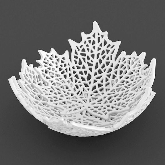
Design Inspiration
To develop the leaf bowl design, I explored various nature-inspired concepts and collected reference images from online design platforms. The maple leaf pattern selected for this project was inspired by publicly available visual references from Pinterest, which helped guide the overall shape and contour of the final design.
Reference Source: Pinterest – Maple Leaf References
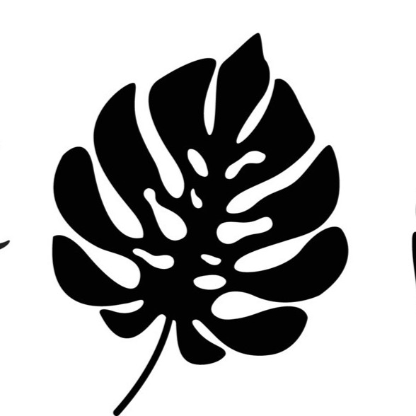
Reference Image
To develop the final design, I explored various nature-inspired patterns and leaf geometries available online. During my research, I found a tropical leaf vector design on Magnific that matched the aesthetic and structural characteristics I wanted for the project. The organic contours, internal cut-outs, and balanced shape made it an excellent candidate for laser cutting.
The reference image was used only as an inspiration source to understand the overall form and visual appearance of the design. Based on this reference, I recreated the geometry as a vector profile and prepared it for fabrication by converting it into a DXF file suitable for laser cutting operations.
Reference Source: Magnific – Tropical Leaf DXF Reference
Design Workflow
To create the final leaf design, I first searched for inspiration images online and selected a maple leaf pattern that matched my design requirements. The reference image was imported into a vector design environment where the outer profile was traced to create a clean vector geometry.
After tracing, unnecessary details were removed and the geometry was refined to ensure all boundaries were properly connected. The completed vector drawing was then exported as a DXF file, which is the standard format commonly used for CNC and laser cutting applications.
Machining Process
CypCut Software
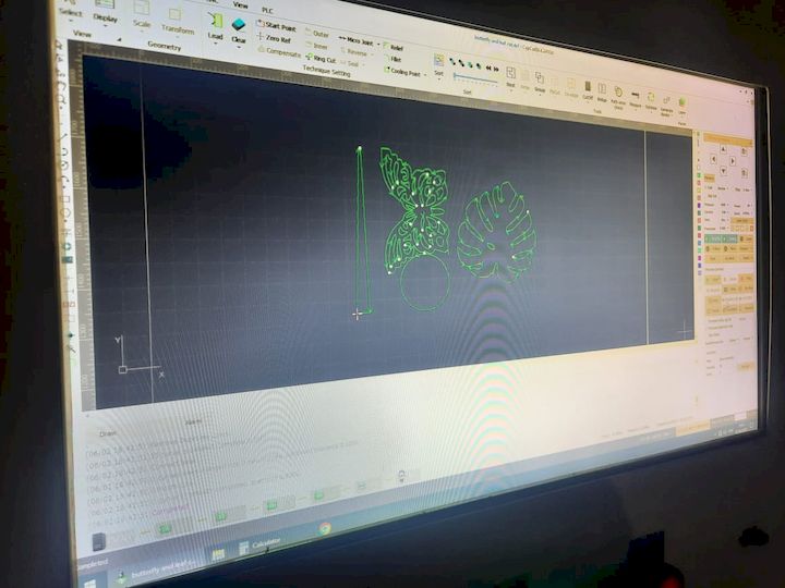
CypCut is a professional CAM and machine control software widely used in fiber laser cutting systems. It provides an integrated platform for importing CAD files, generating cutting paths, nesting components, configuring cutting parameters, and controlling the laser cutting machine. The software supports common design formats such as DXF and allows operators to optimize cutting sequences for improved efficiency and material utilization.
One of the key advantages of CypCut is its user-friendly interface, which combines design preparation and machine control within a single environment. The software enables users to adjust laser power, cutting speed, lead-in and lead-out paths, and other process parameters according to the material type and thickness. These features help achieve accurate cuts while minimizing material waste and processing time.
In industrial fabrication environments, CypCut is commonly used with fiber laser cutting machines for processing materials such as stainless steel, mild steel, aluminum, brass, and copper. Its advanced nesting and path optimization capabilities make it a popular choice for high-precision sheet metal manufacturing.
Official Software Download:
Bochu / CypCut Download Page
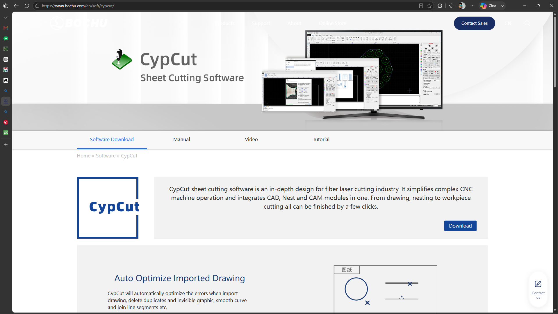
Figure: CypCut software interface showing imported DXF geometry and cutting path preparation before fabrication.
DXF File Preparation and Transfer
I began by converting a downloaded Leaf Image image into a DXF (Drawing Exchange Format) file using vector design software. This format is widely supported by laser cutting machines for precision cutting tasks. Once the conversion was complete, I transferred the DXF file to the laser cutter's system. I ensured that all paths and outlines were correctly aligned and prepared the file for accurate cutting operations.
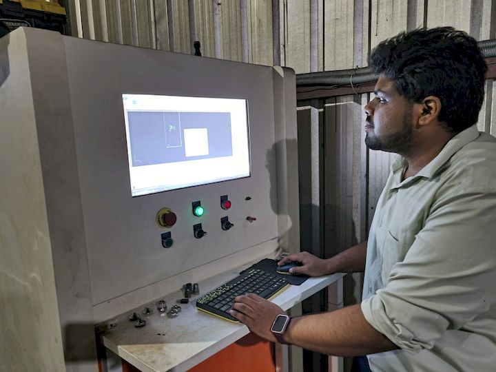
The DXF file was imported into the laser cutting machine software used by the vendor. The software was used to position the design, generate the cutting path, and configure the machining parameters required for fabrication. Based on the machine setup, the software appeared to be an industrial laser cutting CAM platform commonly used with fiber laser cutting systems.
Laser Cutting Safety Considerations
- Wear safety glasses when observing laser cutting operations.
- Ensure proper ventilation and fume extraction.
- Keep flammable materials away from the machine.
- Verify material compatibility before cutting.
- Follow machine operating procedures and emergency stop protocols.
- Avoid direct exposure to laser radiation.
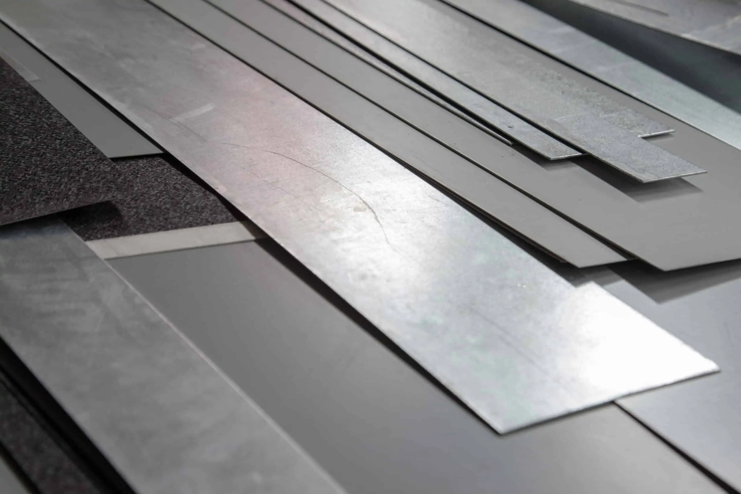
Material Selection: 0.8 mm CBR Aluminum Sheet
The design was fabricated using a 0.8 mm thick CBR aluminum sheet. Aluminum was selected because it offers a good balance between strength, corrosion resistance, lightweight properties, and laser cutting compatibility. The thin sheet thickness also allowed intricate contours to be produced with clean edges and minimal material deformation.
Machine Setup and Parameter Configuration
After transferring the DXF file to the laser cutting machine, the cutting paths were reviewed and refined to ensure smooth and accurate contours. The machine parameters were then configured according to the selected material and its thickness. Important settings such as laser height, cutting speed, and laser power were adjusted to achieve optimal cutting performance. Proper parameter selection is essential for producing clean edges, maintaining dimensional accuracy, and preventing material damage during fabrication.
Configuring machine parameters before starting the laser cutting process.
Executing the Laser Cutting Process
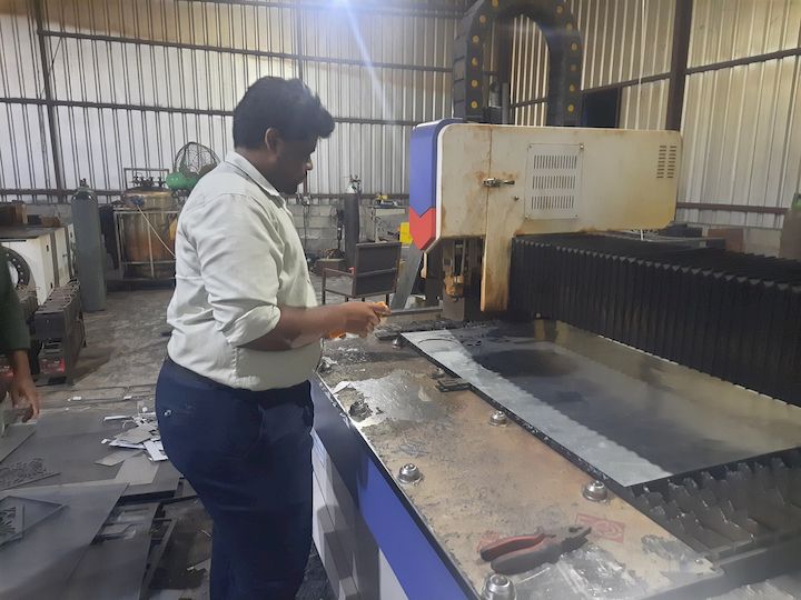
Once all settings and dimensions were verified, the cutting process was initiated. During operation, the laser cutter precisely followed the toolpath generated from the DXF file, producing the desired geometry on the 0.8 mm aluminum sheet. Continuous monitoring was performed throughout the process to ensure accurate cutting, maintain edge quality, and verify that the machine operated within the configured parameters.
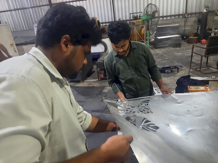
Laser cutting operation in progress.
Final Output and Results
The completed leaf design demonstrates the precision and effectiveness of the metal laser cutting process. The final output features clean edges, accurate dimensions, and well-defined contours that closely match the original CAD design. The successful fabrication highlights the importance of proper file preparation, machine setup, and process control in achieving high-quality results.
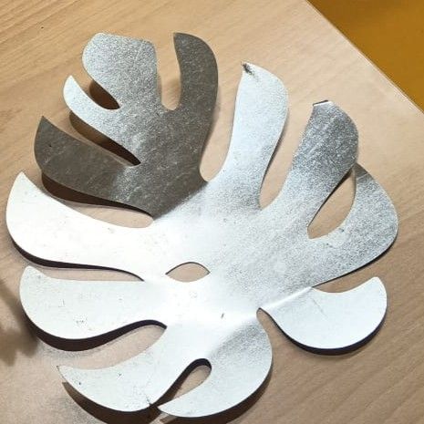
Completed laser-cut aluminum leaf design.
Post-Cutting Inspection and Quality Check
After the cutting operation was completed, the fabricated component was removed from the machine and carefully inspected. The dimensions and overall geometry were compared against the original design to verify accuracy and consistency. This inspection process ensured that the final product met the required specifications and maintained the intended design quality.
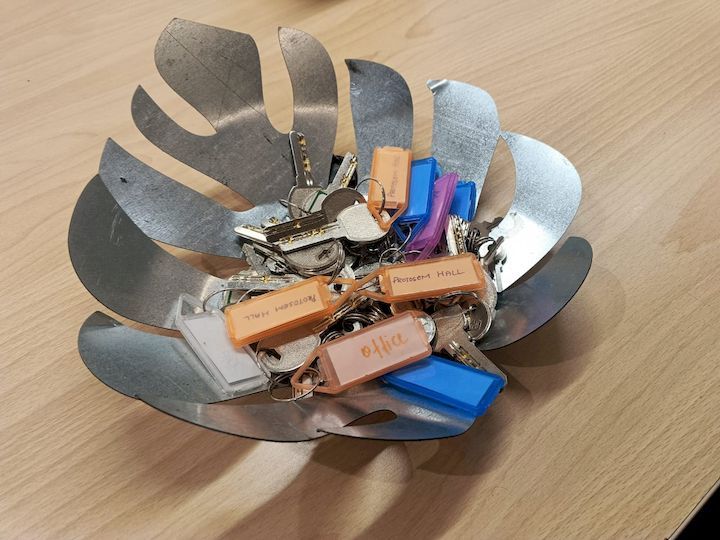
As part of the final evaluation, I held the fabricated component to observe its appearance, edge quality, and overall finish. This practical inspection helped connect the digital design process with the physical outcome and provided a better understanding of the capabilities of industrial laser cutting technology.
Learning Summary
This week introduced me to industrial metal laser cutting and its digital fabrication workflow. I learned how to convert a reference image into a manufacturing-ready DXF file, understand machine setup requirements, and observe how CAD geometry is transformed into a finished metal component. Through this process, I gained valuable exposure to industrial fabrication techniques, material considerations, and safety practices associated with high-precision laser cutting systems.