- Week 1 : Project Management
- Week 2 : Computer-aided
- Week 3 : Computer Controlled Cutting
- Week 4 : Embedded Programming
- Week 5 :3D Scanning and Printing
- Week 6 : Electronic Design
- Week 7 : Computer Controlled Machining
- Week 8 : Electronics Production
- Week 9 : Input Devices
- Week 10 : Output Devices
- Week 11 : Networking and Communication
- Week 12 : Mechanical Design and Machine Design
- Week 14 : Molding and Casting
- Week 15 : Interface and Application Programming
- Week 16 : System Integeration
- Week 17 : Wildcard Week
- Week 18 : Applications and Implications, Project Development
- Week 19 : Invention, Intellectual property and Income
- Week 20 : FInal Project Requirements
Automated CNC Foam Cutter Machine
Group Assignment
The complete group documentation for the Automated CNC Foam Cutter Machine can be accessed below:
View Group AssignmentIntroduction
The Automated CNC Foam Cutter Machine was developed as a collaborative machine-building project to automate the process of cutting foam sheets into precise two-dimensional profiles. The machine utilizes a heated nichrome wire and a computer-controlled motion system to produce accurate cuts directly from digital designs.
Before this project, foam cutting in the laboratory was primarily performed using manually operated thermal cutting tools. Although functional, the manual process presented several challenges, including limited cutting accuracy, inconsistent results, longer fabrication times, and potential safety concerns during operation. These limitations motivated us to develop an automated solution capable of improving productivity, precision, and user safety.
The machine was designed as a two-axis CNC system controlled using GRBL firmware running on an Arduino Uno. Motion is achieved through NEMA 17 stepper motors driven by A4988 motor drivers mounted on a CNC Shield V3. The cutting paths are generated from digital designs, converted into G-code, and executed through Universal G-Code Sender (UGS), enabling automated and repeatable foam cutting operations.
Through this project, our team successfully designed, assembled, tested, and validated a functional CNC foam cutting machine capable of producing accurate foam components for prototyping, educational projects, architectural models, and fabrication workflows. This project also provided valuable experience in machine design, electronics integration, motion control systems, software configuration, and collaborative engineering practices.
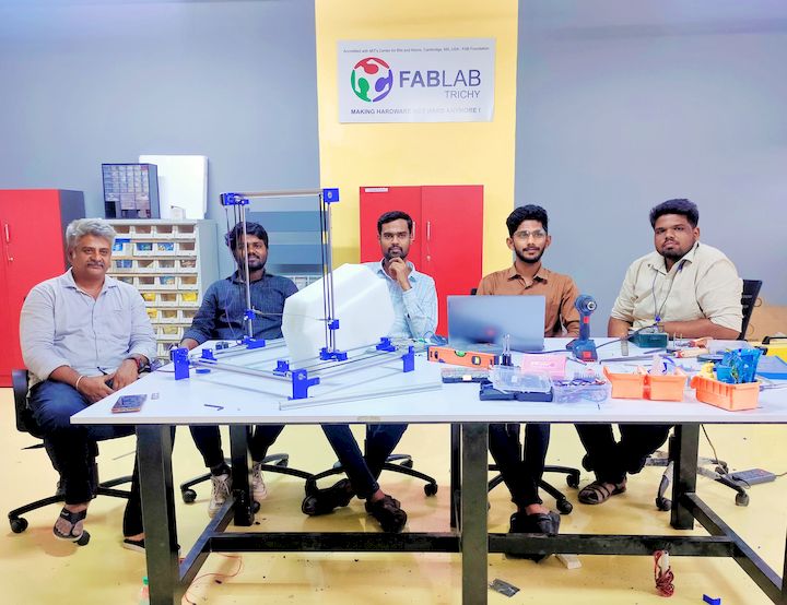
Final assembled Automated CNC Foam Cutter Machine developed during Machine Design Week.
Problem Statement
Foam materials are widely used in prototyping, architectural modeling, packaging, and educational projects due to their lightweight nature and ease of machining. In our lab, foam cutting was primarily performed using a manually operated thermal cutting machine. While suitable for basic cutting operations, the manual process presented several limitations that affected productivity, accuracy, and user safety.
One of the major challenges was the lack of precision and repeatability. Since the cutting process depended entirely on manual movement, producing identical parts consistently was difficult. Complex profiles and intricate shapes were also challenging to fabricate accurately using the existing setup.
Safety was another significant concern. The cutting process required users to manually guide the material near a heated cutting wire, increasing the risk of accidental contact and potential injury. Additionally, prolonged manual operation often resulted in operator fatigue and inconsistent cutting quality.
To overcome these limitations, there was a need for an automated foam cutting solution capable of executing precise cutting paths directly from digital designs. The proposed CNC Foam Cutter Machine was developed to improve cutting accuracy, repeatability, safety, and overall fabrication efficiency while providing students with a reliable tool for rapid prototyping and model making.
Demonstration of the manual foam cutting process and its associated challenges.
Challenges associated with conventional manual foam cutting methods.
Project Objectives
The primary objective of this project was to design and develop an automated CNC Foam Cutter Machine capable of producing accurate two-dimensional foam profiles directly from digital designs. The machine was intended to improve cutting precision, enhance user safety, and reduce the limitations associated with manual foam cutting methods.
- Design and fabricate a robust two-axis CNC machine structure suitable for foam cutting applications.
- Integrate stepper motors, motor drivers, and control electronics to achieve precise and repeatable machine motion.
- Implement GRBL-based motion control using an Arduino Uno and CNC Shield V3.
- Generate and execute G-code through Universal G-Code Sender (UGS) for automated operation.
- Improve operator safety by minimizing direct interaction with the heated cutting wire during machining.
- Achieve consistent cutting quality and repeatability for educational and prototyping applications.
- Develop a low-cost and easily maintainable machine using readily available fabrication and electronic components.
Team Planning and Task Allocation
The development of the Automated CNC Foam Cutter Machine was carried out through a collaborative effort involving members from Fab Lab Nellai and Fab Lab Trichy. During the initial planning phase, the project requirements were discussed and divided into mechanical fabrication, electronics integration, software configuration, machine assembly, testing, documentation, and presentation activities. This structured approach allowed the team to work efficiently and complete the machine within the allotted time.
Each team member was assigned responsibilities based on their skills and areas of interest. Regular discussions and progress reviews were conducted throughout the development process to ensure proper coordination between mechanical, electrical, and software subsystems.
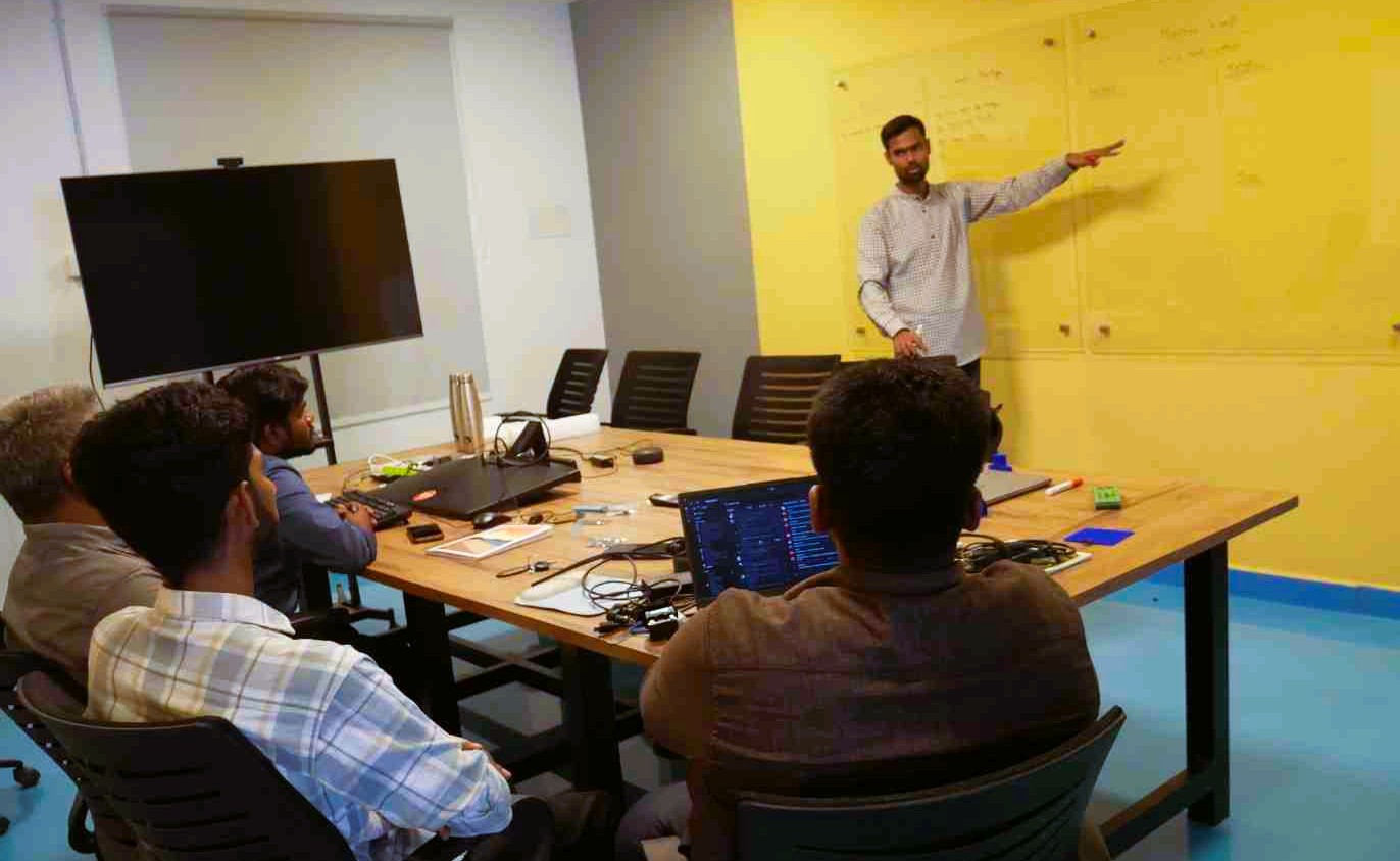
Team Discussion on the Task Planning and Allocation
| Team Member | Responsibilities | Individual Documentation |
|---|---|---|
| Muhesh Kumar | Electronics integration, CNC Shield wiring, motor driver setup, GRBL configuration, machine testing, filament selection, mechanical assembly support, validation, and documentation. | View Documentation |
| Gayatri Prasad | Mechanical fabrication, frame preparation, structural assembly, and fabrication workflow support. | View Documentation |
| Uthaya Velraj | Electronics assembly, controller integration, wiring verification, troubleshooting, and hardware validation. | View Documentation |
| Manikandan | 3D printing of machine components, post-processing, final video editing, and presentation preparation. | View Documentation |
Individual Contribution
As part of the Automated CNC Foam Cutter Machine development team, my primary contribution focused on the machine control electronics and motion control setup. I was responsible for assembling the CNC Shield with the Arduino Uno, installing and calibrating the A4988 motor drivers, configuring the NEMA 17 stepper motors, and validating the electrical connections.
I performed motor driver current calibration using a multimeter to ensure safe operation of the stepper motors. In addition, I installed and configured GRBL firmware on the Arduino Uno and established communication with Universal G-code Sender (UGS) for machine control.
After configuring the software environment, I tested motor movements, verified axis directions, and assisted in machine commissioning. These activities ensured reliable machine operation and provided the foundation for executing G-code during the foam cutting process.
I also documented the machine setup procedure, calibration workflow, and software configuration process for future users and maintenance activities.
Individual Contribution
Electronics Integration and Machine Control Setup
The electronics subsystem of the CNC Foam Cutter Machine consists of an Arduino-based motion controller, motor drivers, power distribution components, and stepper motors. These components work together to interpret G-code instructions and convert them into precise mechanical movements.
- Arduino Uno R3
- CNC Shield V3
- A4988 Stepper Motor Drivers
- NEMA 17 Stepper Motors
- 12V DC Power Supply
- USB Communication Cable
- Multimeter for Calibration
- Connecting Wires and Terminal Connectors
Stepper Motor (NEMA 17)
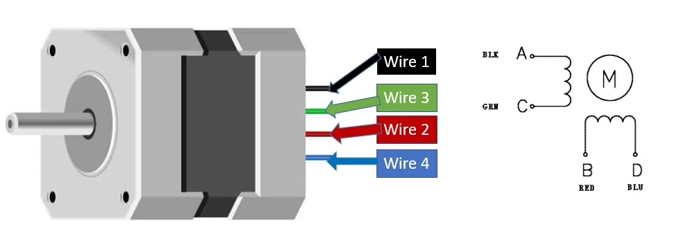
A stepper motor is a brushless DC motor that rotates in precise angular increments called steps. Unlike conventional DC motors, stepper motors can accurately control position, speed, and direction without requiring a feedback system. This makes them ideal for CNC machines, 3D printers, robotic systems, laser engravers, and automation equipment.
The NEMA 17 stepper motor is one of the most widely used motors in CNC applications. It typically has a step angle of 1.8°, which means it requires 200 steps to complete one full revolution. The motor consists of multiple coils that are energized in sequence to produce rotational movement.
Key Specifications
| Parameter | Value |
|---|---|
| Motor Type | Bipolar Stepper Motor |
| Frame Size | NEMA 17 |
| Step Angle | 1.8° |
| Steps per Revolution | 200 Steps |
| Rated Voltage | 2V – 12V (Model Dependent) |
| Current Rating | 1A – 2A |
| Holding Torque | Typically 40–60 N·cm |
Applications
- CNC Machines
- 3D Printers
- Laser Engravers
- Pick and Place Machines
- Industrial Automation Systems
- Robotic Platforms
A4988 Stepper Motor Driver
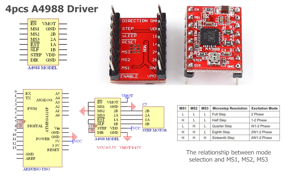
A4988 Stepper Driver Datasheet and Pin Configuration
The A4988 is a microstepping motor driver designed to control bipolar stepper motors with high precision and efficiency. It simplifies motor control by requiring only two signals from the microcontroller: STEP and DIR. The driver internally manages the switching sequence required to energize the motor coils.
One of the major advantages of the A4988 driver is its ability to perform microstepping. Depending on the configuration of the MS1, MS2, and MS3 pins, the driver can operate in Full Step, Half Step, Quarter Step, Eighth Step, and Sixteenth Step modes. This results in smoother motion and improved positioning accuracy.
Features of A4988 Driver
- Operating Voltage: 8V – 35V
- Logic Voltage: 3V – 5.5V
- Current Output: Up to 2A per Coil
- Microstepping Support up to 1/16 Step
- Thermal Shutdown Protection
- Overcurrent Protection
- Simple STEP and DIR Interface
- Adjustable Current Limiting
A4988 Pin Description
| Pin | Function |
|---|---|
| STEP | Receives pulse signal for stepping |
| DIR | Controls motor direction |
| ENABLE | Enables or disables the driver |
| MS1, MS2, MS3 | Selects microstepping mode |
| VMOT | Motor power supply input |
| GND | Ground connection |
The motor speed can be controlled by changing the pulse frequency on the STEP pin, while the rotation direction can be changed using the DIR pin.
Arduino CNC Shield V3
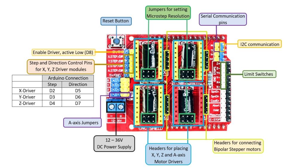
Arduino CNC Shield V3 Layout and Connections
The Arduino CNC Shield V3 is an expansion board specifically designed for CNC and motion control applications. The shield mounts directly on top of an Arduino Uno and provides dedicated sockets for stepper motor drivers such as the A4988 and DRV8825.
It supports up to four axes of motion control and includes connections for stepper motors, limit switches, spindle control, and external power supply inputs. The shield is commonly used with GRBL firmware for CNC routers, laser engravers, plotters, and automated manufacturing systems.
Features of CNC Shield V3
- Supports X, Y, Z, and A Axes
- Compatible with A4988 and DRV8825 Drivers
- Direct Arduino Uno Compatibility
- Dedicated Limit Switch Connections
- Spindle and Laser Control Outputs
- Supports External Power Supply (12V–36V)
- GRBL Firmware Compatible
CNC Shield Specifications
| Parameter | Specification |
|---|---|
| Compatible Board | Arduino Uno |
| Motor Driver Support | A4988 / DRV8825 |
| Number of Axes | 4 Axes |
| Input Voltage | 12V – 36V DC |
| Limit Switch Support | Yes |
| GRBL Compatible | Yes |
Working Principle of the Complete CNC System
In a CNC machine, the Arduino Uno running GRBL firmware interprets G-code commands and generates STEP and DIR signals. These signals are routed through the CNC Shield to the A4988 motor drivers. The A4988 drivers then energize the stepper motor coils in the correct sequence, resulting in accurate rotational movement and precise positioning of the machine axes.
- Arduino Uno receives G-code commands.
- CNC Shield distributes STEP and DIR signals.
- A4988 driver converts signals into motor coil currents.
- Stepper motor rotates accurately.
- Machine performs cutting, engraving, or positioning operations.
The combination of Arduino Uno, CNC Shield V3, A4988 driver modules, and NEMA 17 stepper motors provides a low-cost and highly reliable motion control platform widely used in CNC machining and automation projects.
CNC Shield and Motor Driver Integration
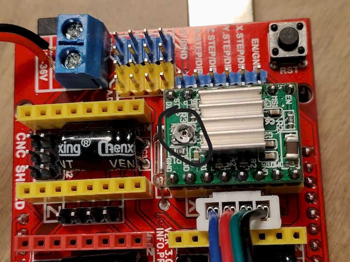
After gathering the required electronic components, I began the machine control setup by integrating the CNC Shield V3 with the Arduino Uno R3. The CNC Shield acts as an interface between the Arduino and the stepper motor drivers, simplifying motor connections and providing dedicated sockets for motion control.
The CNC Shield was carefully mounted onto the Arduino Uno, ensuring proper alignment of all header pins. Once the shield was secured, A4988 stepper motor drivers were installed into the designated driver slots. Special attention was given to the orientation of each driver because incorrect installation could permanently damage both the driver and the control board.
The A4988 drivers are responsible for converting the STEP and DIRECTION signals generated by the GRBL firmware into controlled current outputs for the stepper motors. These drivers also support microstepping, which improves motion smoothness and positioning accuracy during machine operation.
Before connecting the motors, all driver orientations were verified against the CNC Shield layout and datasheet recommendations. This verification step was important to prevent wiring errors and ensure safe operation of the machine electronics.
CNC Shield V3 mounted on Arduino Uno with A4988 stepper motor drivers installed.
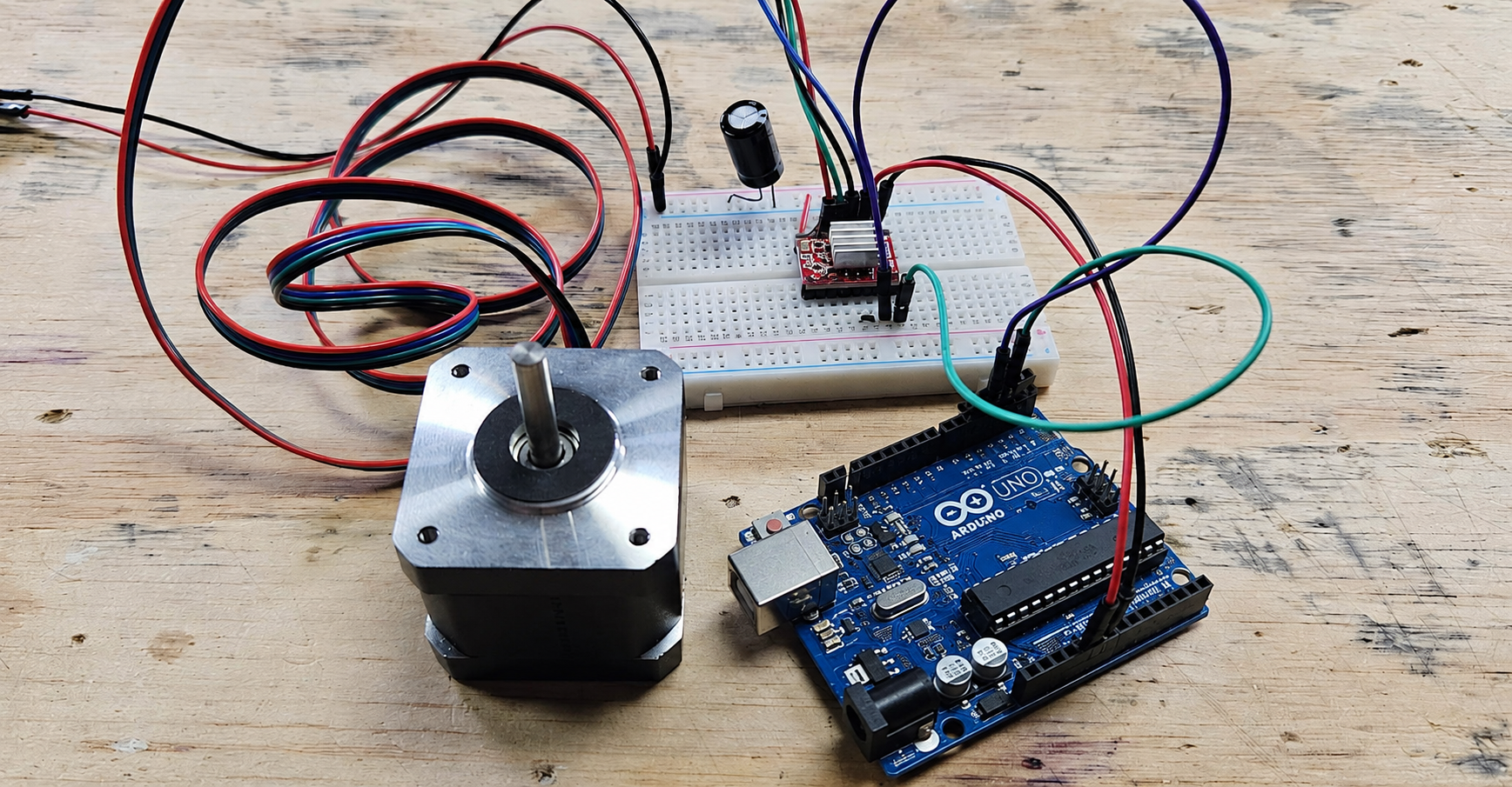
Stepper Motor Wiring and Connections
Once the CNC Shield and A4988 motor drivers were installed, the next step was connecting the NEMA 17 stepper motors responsible for machine movement. The CNC Foam Cutter Machine utilizes stepper motors because of their ability to provide accurate positioning and repeatable motion, which are essential for CNC applications.
Before connecting the motors, the coil pairs of each NEMA 17 stepper motor were identified using a multimeter. Correct identification of the motor coils is important because an incorrect connection can cause motor vibration, irregular movement, or complete failure to rotate.
After identifying the coil pairs, the motor wires were connected to the corresponding output terminals on the CNC Shield. The X-axis and Y-axis motors were connected to their designated driver channels, ensuring that each motor received the appropriate STEP and DIRECTION signals generated by the GRBL controller.
Following the wiring process, all electrical connections were verified to ensure proper continuity and secure terminal connections. This verification step helped prevent wiring errors and ensured reliable machine operation during subsequent testing and calibration procedures.
Connecting NEMA 17 stepper motors to the CNC Shield for X-axis and Y-axis motion control.
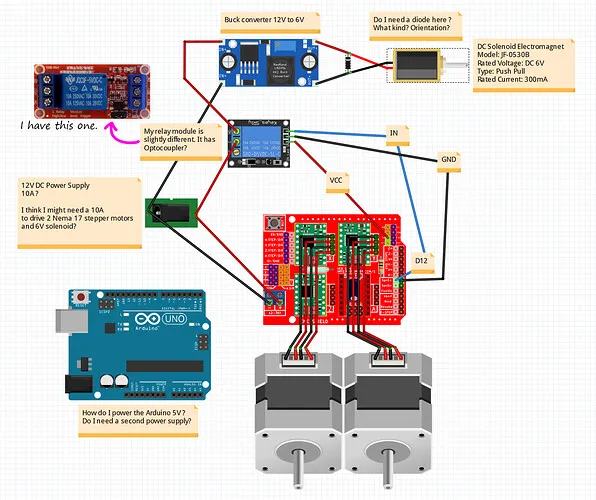
Power Supply Integration
After completing the motor wiring connections, the next step was integrating the power supply required for operating the machine. The CNC Shield and stepper motors require an external power source because the current supplied through the Arduino USB connection is insufficient to drive the motors under load.
A 12V DC power supply was connected to the power input terminal of the CNC Shield. The positive terminal of the power supply was connected to the VCC input, while the negative terminal was connected to the GND terminal. Proper polarity was verified before powering the system to prevent accidental damage to the electronics.
The external power supply provides the necessary current for the A4988 motor drivers and NEMA 17 stepper motors, enabling stable machine operation during movement. Using a dedicated power source also improves motor performance and prevents communication interruptions between the Arduino and the computer.
Before powering the machine, all wiring connections were inspected to ensure secure terminals and correct polarity. This verification step helped eliminate potential electrical faults and ensured safe startup of the control system.
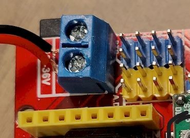
Connecting the external 12V DC power supply to the CNC Shield for motor operation.
Before operating the machine, it was necessary to calibrate the A4988 stepper motor drivers to ensure safe and reliable motor performance. The A4988 drivers allow the maximum motor current to be adjusted through a reference voltage (Vref), which helps prevent overheating of both the driver and the stepper motor.
Using a digital multimeter, I measured the reference voltage directly from the potentiometer on each A4988 driver while the CNC Shield was powered. The negative probe of the multimeter was connected to the system ground, while the positive probe was placed on the adjustment potentiometer to measure the Vref value.
The reference voltage was adjusted carefully using a precision screwdriver until the desired value was achieved. For the NEMA 17 stepper motors used in this machine, the Vref was maintained within the recommended operating range to provide sufficient torque while preventing excessive current draw.
Proper driver calibration is a critical step in machine commissioning because incorrect settings can lead to missed steps, unstable motion, excessive heat generation, or permanent damage to the motor drivers. After calibration, the motors operated smoothly and responded accurately to control commands issued by the motion controller.
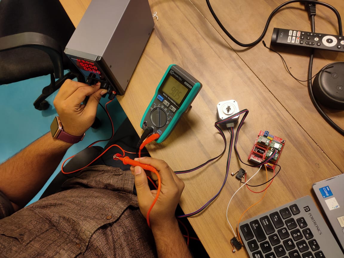
Measuring and adjusting the A4988 driver reference voltage (Vref) using a digital multimeter.
Calibration Procedure
- Switch off the power supply before making any adjustments.
- Connect the multimeter in DC voltage measurement mode.
- Place the negative probe on GND and the positive probe on the driver potentiometer.
- Power on the CNC Shield and observe the measured Vref value.
- Adjust the potentiometer carefully using a precision screwdriver.
- Verify that the voltage remains within the recommended operating range.
- Repeat the process for all installed motor drivers.
GRBL Firmware Installation and Configuration
After completing the hardware assembly and motor driver calibration, the next step was configuring the machine controller by installing GRBL firmware on the Arduino Uno. GRBL is an open-source motion control firmware that interprets G-code commands and generates the STEP and DIRECTION signals required to drive the stepper motors through the CNC Shield.
The firmware was installed using the Arduino IDE. After connecting the Arduino Uno to the computer through a USB cable, the GRBL library was added to the Arduino IDE and the GRBL upload example was opened. The firmware was then compiled and uploaded to the Arduino board, transforming it into a dedicated CNC motion controller.
Once the upload process was completed successfully, the Arduino was able to receive G-code commands and control the machine's movement. This firmware acts as the bridge between the machine hardware and the software used to generate and send machining instructions.
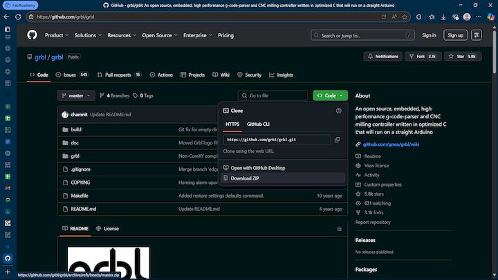
Uploading GRBL firmware to the Arduino Uno using the Arduino IDE.
GRBL GitHub Repository:
https://github.com/gnea/grbl
GRBL Installation Procedure
- Connect the Arduino Uno to the computer using a USB cable.
- Open the Arduino IDE.
- Install the GRBL library if it is not already available.
- Navigate to File → Examples → grbl → grblUpload.
- Select Arduino Uno as the board.
- Select the correct COM port.
- Compile and upload the firmware.
- Verify that the upload completes successfully.
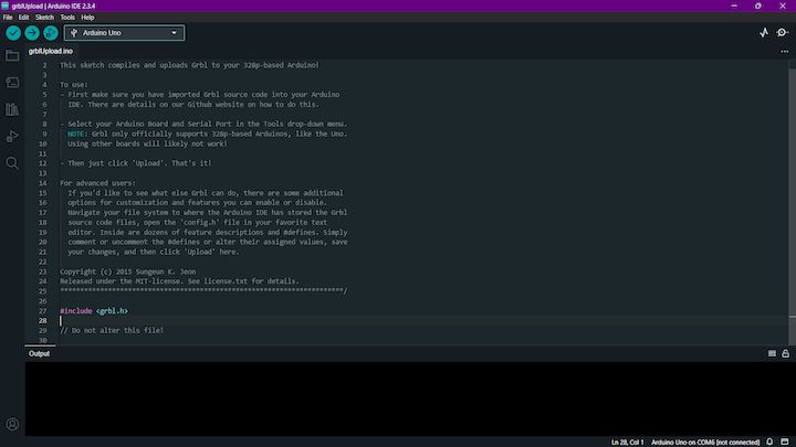
Successful installation of GRBL firmware on the Arduino Uno.
B. Download and Run UGS (Universal Gcode Sender)
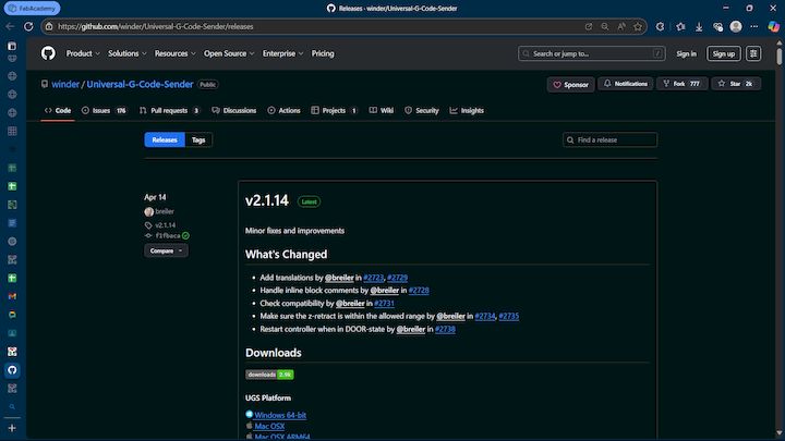
- Download UGS Platform from: UGS GitHub Releases
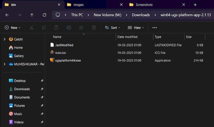
- Extract the folder.
- Open: bin > ugsplatform.exe (Windows) or run .sh for Linux/macOS.
Universal G-Code Sender (UGS) Setup
With the GRBL firmware successfully installed on the Arduino Uno, the next step was establishing communication between the computer and the CNC Foam Cutter Machine. For this purpose, I used Universal G-Code Sender (UGS), an open-source software platform that provides a graphical interface for controlling GRBL-based CNC machines.
UGS allows users to connect to the machine, manually jog the axes, configure machine parameters, monitor machine status, and send G-code files for execution. This software acts as the primary interface between the operator and the machine during operation.
The latest version of UGS Platform was downloaded from the official GitHub repository and installed on the computer. After launching the software, the correct COM port corresponding to the Arduino Uno was selected, and the baud rate was configured according to the GRBL firmware requirements. Once connected successfully, UGS displayed the machine status indicating that communication with the controller had been established.
Universal G-Code Sender (UGS) used for machine control and G-code execution.
UGS Installation Procedure
- Download the latest UGS Platform release from GitHub.
- Extract the downloaded package.
- Launch the UGS Platform application.
- Select the appropriate COM port connected to the Arduino Uno.
- Set the communication baud rate.
- Click the connect button and verify successful communication.
- Confirm that the GRBL status message appears in the console window.
Successful communication established between UGS and the GRBL controller.
After establishing communication, I performed manual jogging operations to verify the movement of both machine axes. This initial verification ensured that the stepper motors, motor drivers, wiring connections, and firmware configuration were functioning correctly before proceeding with machine calibration and testing.
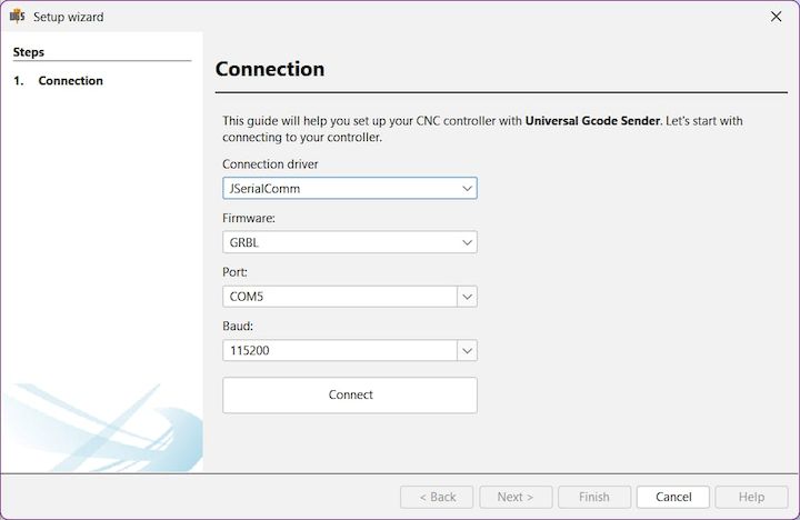
UGS Setup Wizard used to establish communication between the computer and the GRBL-based CNC controller.
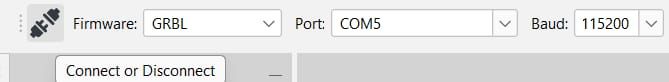
Selecting the GRBL firmware profile, COM port, and baud rate before connecting to the machine.

UGS machine control toolbar providing options for start, stop, pause, homing, and machine control operations.
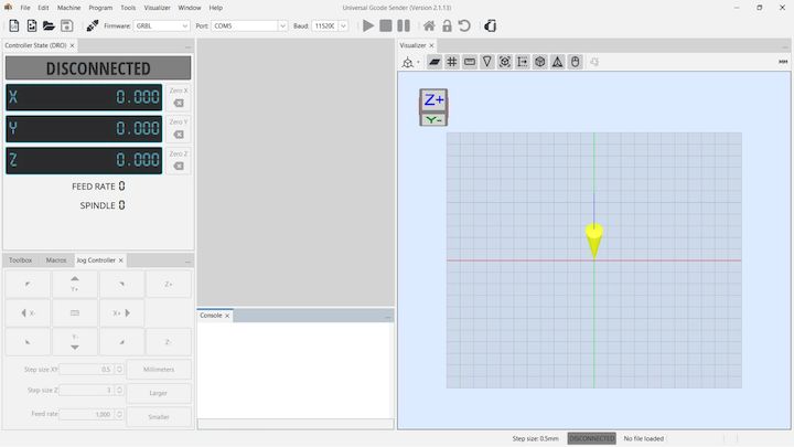
UGS workspace displaying machine coordinates, jog controls, and the visual machine positioning interface.
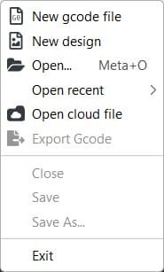
Creating or opening G-code files within UGS for machine operation and testing.
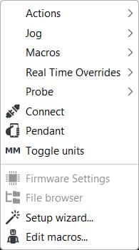
Accessing the Setup Wizard and machine configuration tools available within UGS Platform.
Machine Calibration and Motion Testing
After establishing successful communication between UGS and the GRBL controller, the machine was calibrated and tested to verify proper operation of the motion system. This stage was essential to ensure that both machine axes moved accurately and responded correctly to control commands before executing any cutting operations.
Using the jogging controls available in UGS, I manually moved the X and Y axes in both positive and negative directions. This allowed verification of motor wiring, axis direction, and smooth machine movement. Any unexpected movement or incorrect axis response was corrected through GRBL configuration and wiring verification.
The machine was then calibrated by comparing the commanded movement distance with the actual physical movement of the machine. Small adjustments were made to the GRBL steps-per-millimeter parameters to improve positioning accuracy and ensure repeatable motion during operation.
Throughout the testing process, the machine was operated at different travel distances and speeds to confirm stable performance. These tests verified that the stepper motors, motor drivers, power supply, and control electronics were functioning together correctly and that the machine was ready for cutting operations.
Testing machine movement and verifying axis response using UGS jogging controls.
Verification Checks Performed
- Verified X-axis movement direction.
- Verified Y-axis movement direction.
- Checked smooth motor operation.
- Validated machine response to jog commands.
- Confirmed stable communication between UGS and GRBL.
- Verified repeatable positioning accuracy.
- Ensured reliable operation before executing G-code.
G-Code Execution and Foam Cutting Test
After completing machine calibration and motion verification, the next step was executing a G-code program to validate the overall performance of the CNC Foam Cutter Machine. The objective of this test was to confirm that the machine could accurately follow programmed toolpaths and produce the desired cutting profile.
A sample G-code file was loaded into Universal G-Code Sender (UGS) and reviewed before execution. The machine coordinates were verified, and the foam workpiece was positioned securely within the cutting area. Once all safety checks were completed, the G-code program was transmitted to the GRBL controller through UGS.
During execution, the stepper motors moved the machine along the programmed X and Y axis trajectories while the heated nichrome wire performed the cutting operation. The machine followed the generated toolpath smoothly and demonstrated accurate positioning throughout the machining process.
The cutting operation was continuously monitored to ensure stable machine movement, proper wire heating, and consistent cutting quality. No communication interruptions or motion errors were observed during the test, confirming the reliability of the electronics integration and control system.
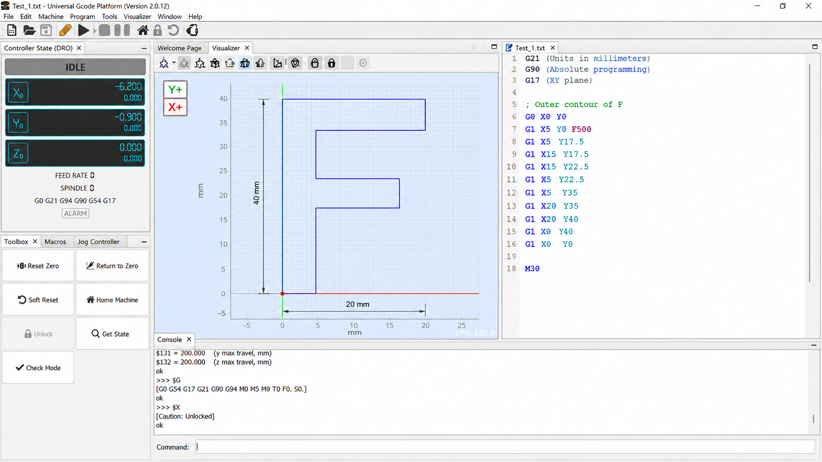
Executing the G-code program through Universal G-Code Sender (UGS).
CNC Foam Cutter Machine performing the cutting operation using a heated nichrome wire.
Observations
- The machine responded correctly to all G-code commands.
- X-axis and Y-axis movements were smooth and repeatable.
- Communication between UGS and GRBL remained stable throughout the operation.
- The heated wire maintained consistent cutting performance.
- The generated profile closely matched the intended design geometry.
- No missed steps or positioning errors were observed during the test.
Final Machine Output
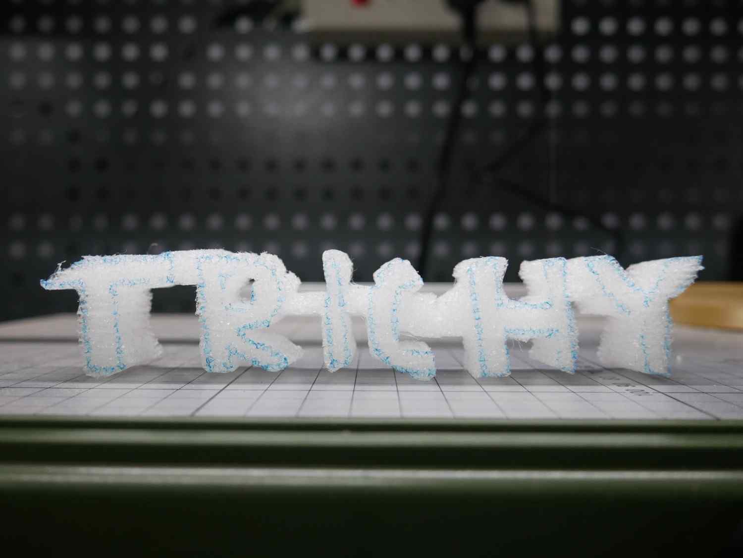
Following successful machine calibration and G-code execution, the CNC Foam Cutter Machine produced the intended cutting profile accurately and consistently. The completed output demonstrated the machine's ability to follow programmed toolpaths while maintaining smooth and controlled motion throughout the cutting process.
The final cut exhibited clean edges and maintained the desired geometric shape without significant deviations. The coordinated movement of the X and Y axes, combined with stable wire heating, contributed to achieving a satisfactory cutting result. This successful outcome validated the effectiveness of the machine design, electronics integration, and control system configuration.
The completed test confirmed that the machine is capable of producing repeatable foam-cutting operations and can be utilized for rapid prototyping, educational demonstrations, architectural models, and fabrication-related applications.
Final foam-cut profile produced using the Automated CNC Foam Cutter Machine.
Results Achieved
- Successful communication between UGS and GRBL controller.
- Accurate execution of the generated G-code.
- Smooth and repeatable machine movement.
- Stable operation of the stepper motor control system.
- Consistent foam cutting performance.
- Successful validation of the machine design and electronics integration.
Problems Faced and Solutions
During the development and testing of the Automated CNC Foam Cutter Machine, several technical and integration challenges were encountered. These issues were systematically identified, analyzed, and resolved through testing and team collaboration. Addressing these challenges helped improve the reliability and performance of the final machine.
| Problem Encountered | Solution Implemented |
|---|---|
| Stepper motors vibrated but failed to rotate properly. | Motor coil pairs were verified using a multimeter and rewired according to the correct phase sequence. |
| Machine axes moved in the opposite direction during jogging. | Motor connector orientation was adjusted and GRBL direction settings were verified. |
| UGS was unable to establish communication with the controller. | Correct COM port selection, baud rate configuration, and USB driver verification were performed. |
| Inconsistent motor performance during initial testing. | A4988 driver reference voltage (Vref) was recalibrated to match the motor specifications. |
| Minor mechanical misalignment during assembly. | Frame components were realigned and all mounting fasteners were retightened. |
| Hot wire temperature variation during early trials. | Power supply connections were checked and wire tension was adjusted for stable operation. |
Future Improvements
Although the Automated CNC Foam Cutter Machine successfully achieved its intended objectives, several enhancements can be implemented in future iterations to improve machine performance, safety, usability, and cutting accuracy. These improvements would increase the machine's capabilities and provide a better user experience during operation.
- Automatic Homing System: Incorporating limit switches on each axis would allow the machine to automatically establish a reference position during startup.
- Improved Wire Temperature Control: Implementing a dedicated temperature control circuit would enable more precise regulation of the nichrome wire temperature for different foam materials and thicknesses.
- Enhanced Safety Features: Adding emergency stop buttons, protective covers, and fault detection mechanisms would improve operator safety during machine operation.
- User-Friendly Interface: A touchscreen-based control panel could simplify machine operation and reduce dependence on external computers.
- Wireless Machine Control: Future versions could incorporate Wi-Fi or Bluetooth connectivity for remote machine monitoring and operation.
- Improved Mechanical Rigidity: Strengthening the machine frame and motion system could further improve positioning accuracy and reduce vibration during operation.
- Advanced Motion Control: Closed-loop stepper motors or servo motors could be used to improve positional feedback and overall machine precision.
These enhancements would help transform the current prototype into a more robust, reliable, and industrially applicable CNC foam cutting system capable of supporting a wider range of fabrication and prototyping applications.
Learning Summary
This week provided practical experience in collaborative machine development. I learned how mechanical systems, electronics, firmware, and software must work together to create a functional CNC machine.
Through configuring the CNC Shield, A4988 drivers, NEMA 17 motors, GRBL firmware, and UGS software, I gained a deeper understanding of motion control systems and machine commissioning procedures.
I also learned the importance of proper driver calibration, wiring verification, machine testing, and systematic troubleshooting during machine development. Working as part of a multidisciplinary team improved my ability to collaborate and contribute effectively to a complete machine-building project.
Downloads
The following files were created and used during my contribution to the Automated CNC Foam Cutter Machine project.
| S.No | File Name | Description | Download |
|---|---|---|---|
| 1 | Machine CAD Files | Mechanical design files used for fabrication. | Download |
| 2 | Electrical Wiring Diagram | CNC Shield and Arduino wiring documentation. | Download |
| 3 | Sample G-Code File | G-code file used for testing and operating the CNC Foam Cutter Machine through UGS Platform. | Download |