- Week 1 : Project Management
- Week 2 : Computer-aided
- Week 3 : Computer Controlled Cutting
- Week 4 : Embedded Programming
- Week 5 :3D Scanning and Printing
- Week 6 : Electronic Design
- Week 7 : Computer Controlled Machining
- Week 8 : Electronics Production
- Week 9 : Input Devices
- Week 10 : Output Devices
- Week 11 : Networking and Communication
- Week 12 : Mechanical Design and Machine Design
- Week 14 : Molding and Casting
- Week 15 : Interface and Application Programming
- Week 16 : System Integeration
- Week 17 : Wildcard Week
- Week 18 : Applications and Implications, Project Development
- Week 19 : Invention, Intellectual property and Income
- Week 20 : FInal Project Requirements
Week 18 : Applications and Implications, Project Development
Objectives of the Week
Scope of the Project
Line Bot is an autonomous line-following robot designed to detect and follow a black path on a white surface using an infrared sensor array. The robot integrates custom electronics, embedded programming, and a laser-cut acrylic structure to create a reliable and efficient educational platform. The goal is to demonstrate real-time motor control and sensor integration using a compact and well-structured system.
Project Plan
Tasks Completed
- Designed and laser-cut the acrylic chassis for the bot.
- Developed and fabricated a custom PCB for motor and sensor connections.
- Integrated XIAO ESP32-C3 with L298N motor driver and IR sensor array.
- Programmed line-following logic with PWM-based motor control.
- Tested the bot for basic navigation and response accuracy.
Tasks Remaining
- Final testing under different lighting conditions and path types.
- Optimize movement for smoother turns and straight-line stability.
- Finalize OLED display for status updates and debugging information.
- Prepare documentation, video presentation, and evaluation material.
Bill of Materials (BoM)
The following table summarizes the major components used in the development of the Line Following Robot. The costs are approximate and may vary depending on supplier and procurement quantity.
| S.No | Component | Description | Quantity | Unit Cost (₹) | Total Cost (₹) |
|---|---|---|---|---|---|
| 1 | XIAO ESP32-C3 | Main microcontroller for robot control and processing | 1 | 750 | 750 |
| 2 | Custom Fabricated PCB | Main control and sensor interface boards | 2 | 150 | 300 |
| 3 | BO Gear Motors | DC geared motors for locomotion | 2 | 180 | 360 |
| 4 | Robot Wheels | Compatible wheels for BO motors | 2 | 60 | 120 |
| 5 | L298N Motor Driver | Dual H-Bridge motor driver module | 1 | 180 | 180 |
| 6 | 5-Channel IR Sensor Array | Line tracking sensor module | 1 | 250 | 250 |
| 7 | OLED Display | 0.96-inch I2C OLED display | 1 | 250 | 250 |
| 8 | JST Connectors & Wiring | Interconnection cables and connectors | 1 Set | 150 | 150 |
| 9 | Header Pins | Male and female pin headers | 1 Set | 50 | 50 |
| 10 | Acrylic Chassis | Laser-cut structural base frame | 1 | 150 | 150 |
| 11 | Rechargeable Battery Pack | Power source for the robot | 1 | 400 | 400 |
| 12 | Fasteners | Screws, nuts, spacers, and mounting hardware | 1 Set | 100 | 100 |
Total Estimated Cost: ₹2,810
The overall cost was kept low by utilizing in-house fabricated PCBs, laser-cut acrylic components, and readily available educational robotics hardware. The design emphasizes affordability, ease of assembly, and suitability for learning embedded systems, PCB design, and autonomous mobile robotics.
Project Summary
The Line Bot project demonstrates the integration of mechanical design, electronics, embedded programming, and system-level engineering into a compact autonomous robotic platform. While the robot is capable of performing autonomous line-following tasks, its primary purpose is to serve as an educational platform that allows learners to explore robotics through practical implementation and experimentation.
By building, programming, and testing the robot, students gain experience in multiple engineering disciplines while developing problem-solving and troubleshooting skills. The project therefore combines both educational and technical objectives within a single platform.
Final Structure
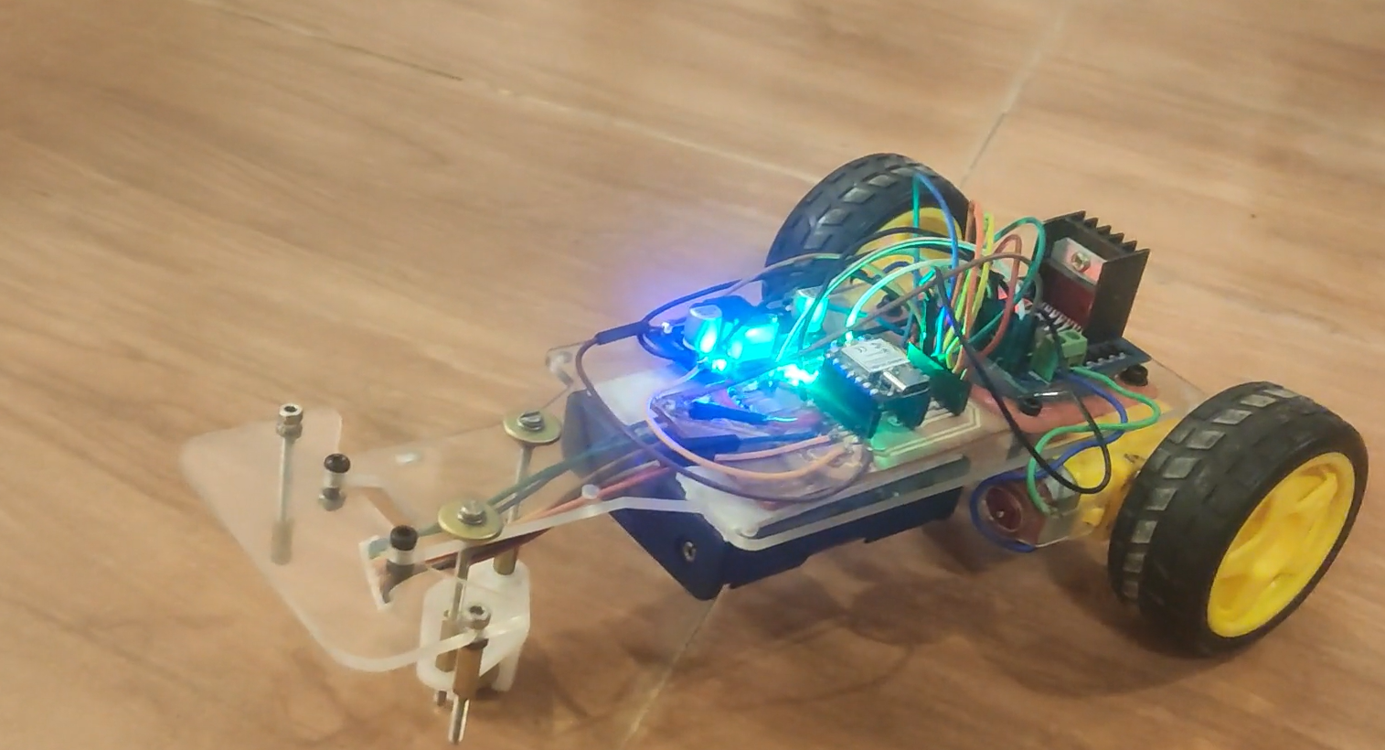
Figure: Final assembled Line Bot integrating the custom PCB, sensor array, motor driver,, and mechanical chassis.
Applications and Implications
The Line Bot project demonstrates the integration of mechanical design, electronics, embedded programming, and system-level engineering into a compact autonomous robotic platform. Although developed as an educational project, the concepts and technologies used in this robot are directly applicable to many real-world industrial and commercial automation systems.
Applications of the Project
- Educational robotics platform for learning embedded systems and automation.
- Autonomous Guided Vehicle (AGV) development for warehouse transportation.
- Material handling systems in manufacturing environments.
- Automated navigation systems used in production lines.
- Research platform for sensor fusion and robot control algorithms.
- Foundation for future autonomous mobile robot (AMR) development.
- Robotics competitions and academic demonstrations.
Industrial Relevance
Modern factories increasingly rely on autonomous systems to improve productivity, safety, and operational efficiency. The fundamental principles demonstrated by the Line Bot—such as path detection, sensor-based decision making, motor control, and embedded processing—are also used in industrial AGVs, warehouse robots, logistics platforms, and autonomous inspection vehicles.
Social and Educational Impact
This project provides a practical learning platform for students to understand robotics, electronics design, PCB fabrication, embedded programming, and system integration. By building a complete robotic system from scratch, learners gain hands-on experience that bridges theoretical knowledge and real-world engineering practices.
Educational Scope of the Project
The educational value of this project extends beyond the final robot itself. The Line Bot is designed to support learning through the complete development process, allowing students to understand how mechanical structures, electronics, embedded software, and fabrication technologies work together in a real robotic system.
Students can assemble the hardware, study the custom PCB design, program the microcontroller, analyze sensor data, and modify the robot's behavior through software development. This hands-on approach provides a practical learning experience that cannot be achieved through theoretical study alone.
The robot, fabrication files, PCB designs, source code, and documentation collectively form an educational toolkit. Rather than simply using a completed robot, learners are encouraged to understand, reproduce, modify, and improve the system as part of the learning process.
This approach promotes experiential learning and helps students develop skills in robotics, electronics, programming, digital fabrication, and engineering design.
Future Scope
- PID-based adaptive line following.
- Wireless monitoring using Wi-Fi or Bluetooth.
- Mobile application integration.
- Obstacle detection and avoidance.
- Computer vision-based navigation.
- Multi-robot communication and coordination.
- AI-assisted autonomous navigation.
Implications for Future Development
The Line Bot serves as a foundational platform that can be expanded into more advanced autonomous systems. The experience gained during this project can be applied to future developments in industrial automation, autonomous mobile robots, smart logistics systems, and intelligent transportation technologies. The project demonstrates how low-cost hardware and open-source development tools can be used to create capable robotic systems with significant real-world relevance.
System Capabilities
What Will You Design?
- Custom PCB for sensor and motor integration.
- Chassis design using 2D CAD for laser cutting.
- Firmware for reading sensor data and executing motor logic.
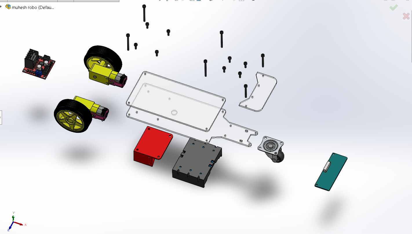
Figure: 3D CAD model of the Line Bot showing component placement and overall mechanical structure.
What Will It Do?
- Follow a predefined black path on a white background using IR sensors.
- Adjust motor speeds based on real-time sensor input to stay on track.
- Display system and sensor status on an onboard OLED display.
- Operate wirelessly with efficient battery management.
Fab Academy Skills Integration
One of the primary objectives of the Fab Academy final project is to demonstrate the integration of knowledge and skills acquired throughout the program. The Line Bot project incorporates concepts, tools, and fabrication processes from multiple weekly assignments and combines them into a fully functional autonomous robotic system.
| Fab Academy Topic | Implementation in Line Bot |
|---|---|
| Computer-Aided Design (2D Design) | The robot chassis was designed using CAD software and exported as DXF files for laser cutting. |
| Computer-Aided Design (3D Design) | Mechanical components and overall assembly were visualized using 3D modelling tools. |
| Computer-Controlled Cutting | The chassis was fabricated using laser cutting on acrylic sheets. |
| 3D Printing (Additive Fabrication) | Custom mounting and support components were produced using additive manufacturing techniques. |
| Electronics Design | A custom PCB was designed to interface sensors, motors, and the microcontroller. |
| Electronics Production | The PCB was fabricated, soldered, assembled, and tested in-house. |
| Embedded Programming | The XIAO ESP32-C3 was programmed to process sensor inputs and control motor outputs. |
| Input Devices | The IR sensor array continuously detects the position of the line and provides feedback to the controller. |
| Output Devices | DC motors and OLED display provide movement and visual feedback respectively. |
| Networking and Communication | The ESP32 platform provides future capability for wireless monitoring and communication. |
| Mechanical Design | The complete robot structure was designed to accommodate electronics, motors, and sensors efficiently. |
| System Integration | All mechanical, electronic, and software subsystems were integrated into a single autonomous robot. |
Final Project Requirements Mapping
The Line Bot project successfully satisfies the major requirements of the Fab Academy final project by incorporating:
- 2D Design through laser-cut chassis development.
- 3D Design through assembly modelling and component visualization.
- Additive Fabrication through 3D printed support components.
- Subtractive Fabrication through laser cutting processes.
- Electronics Design through custom PCB development.
- Electronics Production through PCB fabrication and assembly.
- Embedded Programming through ESP32-C3 firmware development.
- System Integration through the assembly of hardware, electronics, and software into a complete robotic platform.
This integration demonstrates the multidisciplinary engineering workflow required to transform a concept into a fully operational prototype.
Project Development Timeline
The development of the Line Bot project followed a structured engineering workflow, progressing from concept generation to fabrication, electronics integration, programming, testing, and final system validation. Each phase built upon the knowledge and skills acquired during the Fab Academy program.
| Phase | Activity | Status |
|---|---|---|
| Project Planning | Finalized project concept, objectives, and system architecture. | Completed |
| Mechanical Design | Designed robot chassis and component layout using CAD tools. | Completed |
| Computer Controlled Cutting | Laser cut acrylic chassis components and assembled structure. | Completed |
| Electronics Design | Designed custom PCB for sensor and motor interfacing. | Completed |
| Electronics Production | Fabricated, soldered, and tested PCB. | Completed |
| Embedded Programming | Developed firmware for sensor acquisition and motor control. | Completed |
| System Integration | Integrated mechanical, electronic, and software subsystems. | Completed |
| Testing and Debugging | Validated sensor performance, motor response, and navigation accuracy. | Completed |
| Optimization | Improved stability, responsiveness, and overall performance. | In Progress |
| Documentation and Presentation | Prepared project documentation, source files, and demonstration materials. | In Progress |
Major Milestones Achieved
- Successful fabrication of custom robot chassis.
- Development of custom electronics hardware.
- Implementation of line-following control algorithm.
- Integration of OLED display for real-time monitoring.
- Successful autonomous navigation on predefined tracks.
- Completion of mechanical, electronic, and software integration.
Current Project Status
The Line Bot platform has reached a fully functional prototype stage. All core functionalities, including line detection, motor control, embedded processing, and user feedback through the OLED display, have been successfully implemented. The remaining work primarily focuses on optimization, validation testing, and final documentation.
Materials, Sources, and Cost
What Materials and Components Will Be Used?
- ESP32-C3, IR sensor array, L298N motor driver
- BO motors, OLED display, JST connectors
- Laser-cut acrylic chassis and basic hardware
Where Will They Come From?
Components were sourced from Robu.in, local hardware shops, and the Fab Lab inventory. PCB fabrication and laser cutting were done in the Fab Lab.
How Much Will They Cost?
Total estimated cost is ₹3050 (~$37), including electronics and fabrication materials.
Processes Used
- 2D CAD and laser cutting (acrylic chassis)
- PCB design using KiCad and in-house milling
- Embedded programming with Arduino framework
- Soldering and system assembly
- Testing and debugging for sensor accuracy and motor response
Laser Cutting Process
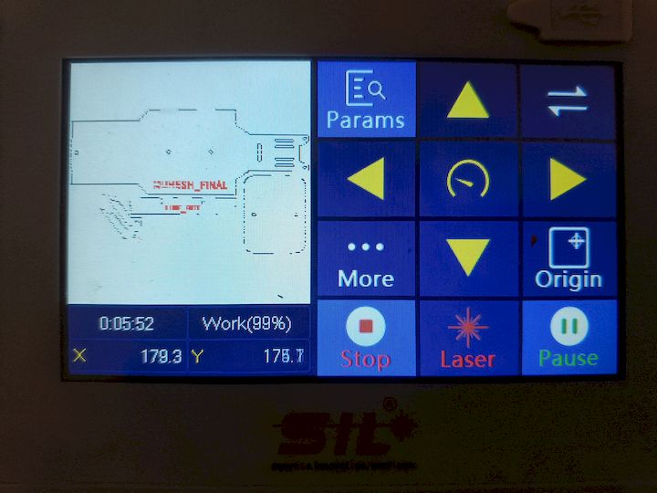
Figure: Laser cutting operation used to manufacture the acrylic chassis components.
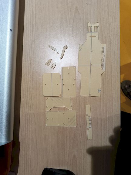
Figure: Acrylic parts after laser cutting and preparation for assembly.
Open Questions and Learnings
What Can Be Improved?
- Can line-following be improved using PID tuning?
- How does lighting or surface quality affect sensor performance?
- Is the system expandable for obstacle avoidance or wireless control?
What Has Worked?
- IR sensor array accurately detects line edges
- ESP32 PWM control delivers responsive motor behavior
- OLED provides helpful debugging information
What Hasn't Worked
- Initial chassis balance issues affected stability
- Sensor jitter under poor lighting required filtering
What Will Happen When?
- Final field testing: Within 2 days
- Documentation and video editing: This weekend
- Final presentation and submission: Before the project deadline
What Have You Learned?
- How to integrate electronics, mechanics, and software effectively
- Importance of system-level debugging and early testing
- Hands-on knowledge of ESP32, PWM, IR sensors, and embedded systems
- How to plan and manage a full project lifecycle in a Fab Lab context
Future Improvements
Although the Line Bot successfully demonstrates autonomous line-following using embedded sensing and motor control, several enhancements can further improve its performance, reliability, and functionality. These improvements would transform the current prototype into a more advanced and intelligent robotic platform.
Performance Improvements
- Implement PID control for smoother and more accurate line tracking.
- Improve sensor calibration to reduce noise and improve detection reliability.
- Optimize motor control algorithms for better speed regulation.
- Enhance battery management and power efficiency.
Hardware Improvements
- Design a compact next-generation PCB with integrated motor driver circuitry.
- Replace the acrylic chassis with a lighter and stronger custom-designed structure.
- Add wheel encoders for closed-loop motion control.
- Improve cable management and overall packaging quality.
Advanced Features
- Add obstacle detection using ultrasonic or ToF sensors.
- Implement wireless monitoring through Wi-Fi or Bluetooth.
- Develop a mobile application for remote monitoring and configuration.
- Introduce data logging for performance analysis and debugging.
Future Research Opportunities
- Computer vision-based path detection using onboard cameras.
- Machine learning-assisted navigation algorithms.
- Autonomous decision-making for dynamic environments.
- Multi-robot communication and cooperative task execution.
- Transformation of the platform into a compact Autonomous Mobile Robot (AMR).
Long-Term Vision
The long-term vision of Line Bot extends beyond a line-following robot. The platform can evolve into a modular educational robotics kit that enables students to learn electronics, programming, robotics, and digital fabrication through hands-on experimentation.
Future versions may incorporate advanced sensing, wireless communication, computer vision, and autonomous navigation capabilities. The project can also serve as a foundation for developing industrial automation prototypes, autonomous mobile robots, and STEM education platforms for schools, colleges, and makerspaces.
Challenges and Solutions
During the development of the Line Bot project, several technical challenges were encountered across mechanical design, electronics integration, programming, and system testing. Addressing these challenges provided valuable engineering experience and contributed significantly to the final system performance.
| Challenge | Impact | Solution Implemented |
|---|---|---|
| Sensor Noise and Jitter | Inconsistent line detection under varying lighting conditions. | Improved sensor placement and optimized detection thresholds through testing. |
| Chassis Stability | Uneven weight distribution affected tracking performance. | Modified component placement and improved overall balance of the robot. |
| Motor Speed Variations | Robot drifted away from the intended path. | Adjusted PWM values and tuned motor control parameters. |
| PCB Assembly Errors | Required additional debugging during initial testing. | Verified connections, continuity, and component orientation before final assembly. |
| Wire Management | Internal wiring affected maintainability and assembly quality. | Introduced JST connectors and organized cable routing. |
| System Integration | Combining mechanical, electronic, and software subsystems required multiple iterations. | Conducted incremental testing and subsystem validation before full integration. |
Key Lessons from Troubleshooting
- Early testing significantly reduces integration complexity.
- Mechanical design directly influences sensor performance and robot stability.
- Proper PCB design and documentation simplify assembly and debugging.
- Incremental development improves reliability and fault isolation.
- System-level testing is essential for achieving consistent autonomous behavior.
Engineering Reflection
One of the most valuable aspects of this project was learning how individual subsystems interact within a complete robotic platform. While each subsystem functioned independently, achieving reliable autonomous operation required careful optimization and integration. The troubleshooting process reinforced the importance of iterative design, validation, and continuous improvement throughout the engineering workflow.
Project Evaluation
The success of the Line Bot project was evaluated by comparing the final prototype against the original project objectives. The evaluation focused on autonomous navigation performance, electronics functionality, software reliability, system integration, and overall usability.
Evaluation Criteria
| Requirement | Target | Result | Status |
|---|---|---|---|
| Line Detection | Reliable detection of black line on white surface | Successfully achieved using IR sensor array | Passed |
| Autonomous Navigation | Follow predefined track without manual intervention | Robot successfully follows the track | Passed |
| Motor Control | Smooth directional control using PWM | Motors respond accurately to sensor inputs | Passed |
| OLED Feedback | Display system information in real time | OLED successfully displays status information | Passed |
| Custom Electronics | Design and fabricate custom PCB | PCB designed, fabricated, assembled, and tested | Passed |
| System Integration | Combine hardware, software, and mechanics into one system | Fully integrated functional prototype completed | Passed |
Testing Procedure
- Verified sensor readings under different lighting conditions.
- Tested motor response for straight movement and turning operations.
- Validated line-following performance on multiple track layouts.
- Checked OLED display updates during operation.
- Performed complete system integration testing.
- Conducted continuous operation tests to evaluate reliability.
Project Outcomes
- Successfully designed and fabricated a custom robotic platform.
- Developed a working embedded control system using XIAO ESP32-C3.
- Integrated custom electronics, sensors, motors, and display modules.
- Demonstrated autonomous line-following behavior.
- Completed a fully operational prototype using Fab Academy workflows.
Assessment Against Initial Goals
The primary objective of developing a compact autonomous line-following robot was successfully achieved. The final prototype demonstrates the integration of mechanical design, electronics production, embedded programming, and system-level engineering. The project satisfies the intended educational and technical goals while providing a strong foundation for future development into more advanced autonomous robotic platforms.
Final Reflection
The Line Bot project represents the culmination of the skills acquired throughout the Fab Academy program. From initial concept development to final system integration, the project required the application of digital fabrication, electronics design, programming, troubleshooting, and documentation. The successful completion of the project demonstrates both technical competency and the ability to transform an idea into a functional engineered system.
Project Files and Resources
To ensure reproducibility and open-source accessibility, all design files, source code, and project documentation related to the Line Bot project are provided below. These files allow anyone to understand, modify, fabricate, and further develop the system.
Source Code
Electronics Design Files
Mechanical Design Files
All files have been developed as part of the Fab Academy final project and are provided to support documentation, replication, future development, and educational use.