- Week 1 : Project Management
- Week 2 : Computer-aided
- Week 3 : Computer Controlled Cutting
- Week 4 : Embedded Programming
- Week 5 :3D Scanning and Printing
- Week 6 : Electronic Design
- Week 7 : Computer Controlled Machining
- Week 8 : Electronics Production
- Week 9 : Input Devices
- Week 10 : Output Devices
- Week 11 : Networking and Communication
- Week 12 : Mechanical Design and Machine Design
- Week 14 : Molding and Casting
- Week 15 : Interface and Application Programming
- Week 16 : System Integeration
- Week 17 : Wildcard Week
- Week 18 : Applications and Implications, Project Development
- Week 19 : Invention, Intellectual property and Income
- Week 20 : FInal Project Requirements
Week 4 : Embedded Programming
Overview
This week's assignment focused on understanding the fundamentals of embedded programming by studying microcontroller datasheets, writing embedded software, and interfacing output devices with a microcontroller. The primary objective was to gain practical experience in developing firmware, understanding hardware-software interaction, and implementing a working embedded application.
Assignment Tasks
- Study the microcontroller datasheet.
- Understand the architecture of the XIAO ESP32-C3.
- Develop and upload embedded firmware.
- Interface an LCD display with a microcontroller.
- Validate the program through practical testing.
- Document the programming workflow and learning outcomes.
My contribution to the group assignment focused on studying the Seeed Studio XIAO ESP32-C3 microcontroller, understanding its datasheet, and exploring communication protocols such as UART, I²C, and SPI. I also worked on interfacing display modules using the I²C protocol and documented the programming workflow, hardware setup, and communication process. This activity helped me gain a deeper understanding of embedded system architecture and hardware-software integration.
The complete group assignment documentation, including experimental procedures, observations, and results from all team members, can be accessed through the Fab Academy Lab page linked below.
Through this collaborative exercise, I learned how different communication protocols are implemented in embedded systems and how development boards can be programmed to interact with external peripherals. The experience also strengthened my understanding of datasheet interpretation, circuit connections, and firmware development.
For this week's assignment, I explored the datasheet of the
Seeed Studio XIAO ESP32-C3
.
Studying the datasheet helped me understand the microcontroller's architecture, pin configuration, communication interfaces, memory organization, power management features, and wireless capabilities. It provided a detailed overview of how a compact development board can integrate processing, connectivity, and I/O functionality within a small footprint. Reviewing the datasheet was an important first step before beginning any programming or hardware interfacing activities.
View XIAO ESP32-C3 Datasheet
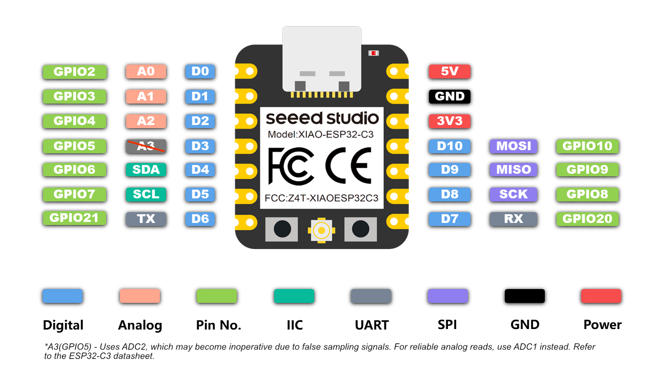
Seeed Studio XIAO ESP32C3 – Key Datasheet Highlights
- 32-bit RISC-V single-core processor at 160 MHz
- Wi-Fi (2.4 GHz) and Bluetooth 5.0 (BLE)
- 400 KB SRAM + 4 MB Flash memory
- 11 multifunctional I/O pins
- 1× UART, 1× I2C, 1× SPI, 4× ADC (12-bit)
- USB Type-C for programming and power
- Ultra-small form factor: 21 x 17.5 mm
- Supports low-power sleep modes
- Built-in RGB LED and reset button
- Ideal for IoT, wearables, and wireless projects
Comparison: Arduino Uno vs Seeed Studio XIAO ESP32C3
| Feature | Arduino Uno | XIAO ESP32C3 |
|---|---|---|
| Processor | ATmega328P (8-bit AVR @ 16 MHz) | ESP32-C3 (32-bit RISC-V @ 160 MHz) |
| Wi-Fi/Bluetooth | None | Wi-Fi + BLE 5.0 |
| Flash Memory | 32 KB | 4 MB |
| SRAM | 2 KB | 400 KB |
| I/O Pins | 14 Digital, 6 Analog | 11 Multipurpose I/Os |
| ADC Resolution | 10-bit | 12-bit |
| USB Type | USB-B | USB-C |
| Power Consumption | Higher | Very Low (Supports sleep modes) |
| Form Factor | Large (68.6 x 53.4 mm) | Ultra-compact (21 x 17.5 mm) |
| Programming Language | Arduino (C++) | Arduino (C++), MicroPython |
| Cost & Availability | Widely available, low cost | Compact, modern, affordable |
Arduino Uno R3 Technical Datasheet
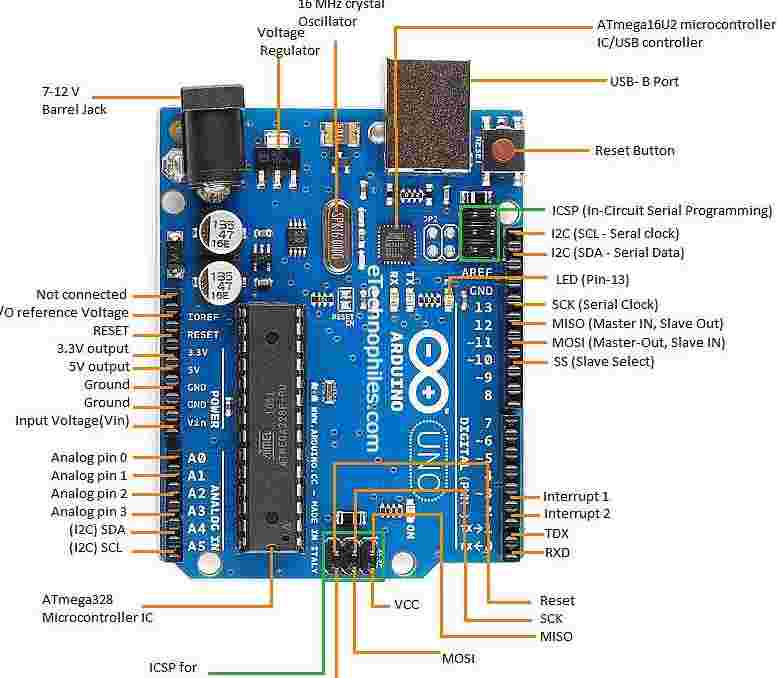
Board Specifications
| Microcontroller | ATmega328P |
|---|---|
| Operating Voltage | 5V |
| Input Voltage | 7-12V (recommended) |
| Digital I/O Pins | 14 (6 provide PWM output) |
| Analog Input Pins | 6 |
| Flash Memory | 32 KB (0.5 KB used by bootloader) |
| SRAM | 2 KB |
| EEPROM | 1 KB |
| Clock Speed | 16 MHz |
| Dimensions | 68.6mm × 53.4mm |
Power Specifications
Power Sources
- USB connection (5V)
- DC power jack (7-12V)
- Vin pin (7-12V)
Additional Resources
Communication Protocols in Embedded Systems
Microcontrollers rarely work alone. In most embedded systems, they communicate with sensors, displays, memory modules, and other controllers through standardized communication protocols. These protocols define how information is transmitted and received between devices. During this week's assignment, I explored three commonly used communication methods: UART, I²C, and SPI.
| Protocol | Lines Required | Speed | Complexity | Applications |
|---|---|---|---|---|
| UART | TX, RX | Moderate | Easy | Serial Monitor, PC Communication |
| I²C | SDA, SCL | Moderate | Medium | OLED Displays, Sensors |
| SPI | MOSI, MISO, SCK, CS | High | Medium | Displays, SD Cards, Memory Devices |
UART Communication
UART (Universal Asynchronous Receiver Transmitter) is one of the simplest communication protocols used in embedded systems. It transfers data through two lines: TX (Transmit) and RX (Receive). Since UART does not require a clock signal, it is commonly used for serial monitoring, debugging, and communication between microcontrollers and computers.
SPI Communication
SPI (Serial Peripheral Interface) is a high-speed communication protocol that uses separate lines for clock and data transfer. It provides faster communication compared to I²C but requires more wiring. SPI is commonly found in TFT displays, SD cards, flash memory devices, and high-speed peripherals.
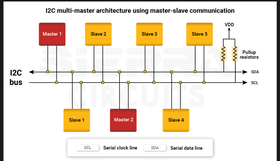
Understanding I²C Communication
For this assignment, I selected an OLED display that communicates using the I²C protocol. I²C, which stands for Inter-Integrated Circuit, is a two-wire communication standard developed to simplify communication between electronic devices.
Only two signal lines are required:
- SDA – Serial Data Line
- SCL – Serial Clock Line
The microcontroller acts as the master device while the OLED display behaves as the slave device. Data is transferred over the SDA line while synchronization is maintained using the SCL clock signal.
One of the major advantages of I²C is that multiple devices can share the same communication bus, reducing the number of wires required in a project.
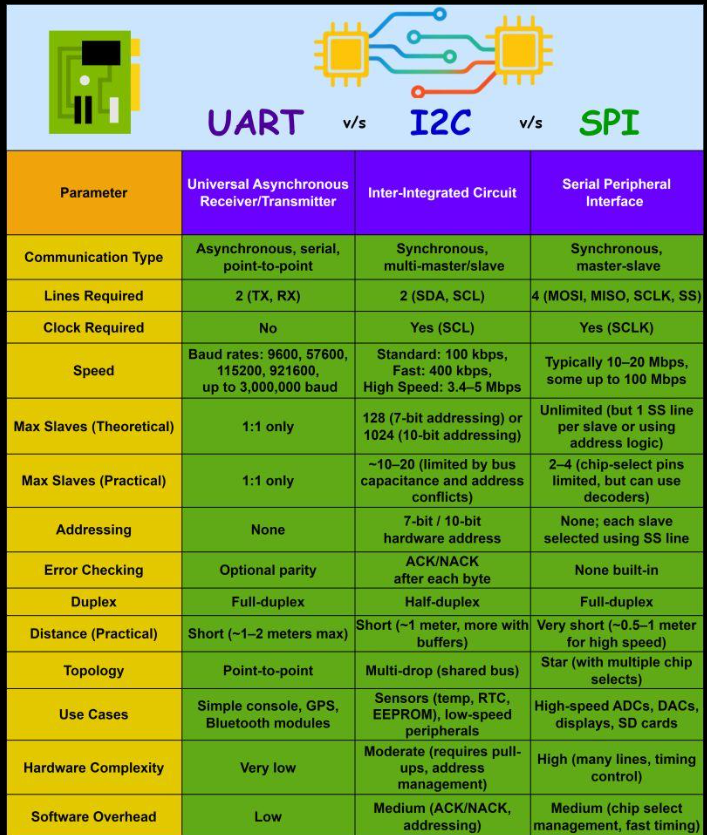
s Comparison of UART, I²C, and SPI communication protocols.
Reference Videos
The following videos helped me understand communication protocols such as UART, I²C, and SPI, as well as the process of interfacing an OLED display with Arduino. These resources provided additional insight into the concepts explored during this assignment.
1. I²C Communication Explained
2. UART vs SPI vs I²C Comparison
Reference Video: SSD1306 OLED Display with Arduino
The following tutorial provides a practical introduction to interfacing an SSD1306 OLED display with Arduino using the I²C communication protocol. It covers hardware connections, library installation, code explanation, and display testing, making it a useful reference while performing this assignment.
Reference tutorial demonstrating SSD1306 OLED display interfacing with Arduino using I²C communication.
Basic I²C communication architecture showing SDA and SCL connections.
Online Electronics Simulators
Online electronics circuit simulators are web-based tools that allow users to design, simulate, and test electronic circuits virtually—without any physical components. These platforms are especially useful for beginners, educators, and hobbyists, as they offer a low-risk environment to learn and experiment.
Key Features
- Drag-and-drop interface for adding components like resistors, transistors, ICs, microcontrollers, etc.
- Real-time simulation of voltages, currents, and logic states.
- Breadboard and schematic views for clearer design understanding.
- Code integration for microcontrollers (Arduino, ESP32, etc.).
- Often cloud-based, allowing projects to be saved and shared online.
Different Online Simulators
| Simulator Name | Features | Ideal For | Download Link |
|---|---|---|---|
| Tinkercad Circuits | Arduino simulation, breadboard view, code editor | Beginners, students | TinkerCAD |
| Falstad Circuit Simulator | Analog and digital simulation, waveform visualization | Intermediate users | Falstad Circuit Simulator |
| EasyEDA | PCB design + simulation, schematic editor | PCB designers | EasyEDA |
| CircuitVerse | Digital logic circuit simulator | Digital electronics learners | CircuitVerse |
| Multisim Live | SPICE simulation, schematic design | Engineering-level projects | Multisim Live |
Introduction to TinkerCAD
TinkerCAD is a free, easy-to-use app for 3D design, electronics, and embedded coding. It's used by designers, hobbyists, teachers, and kids, for creating simple 3D models and circuits.
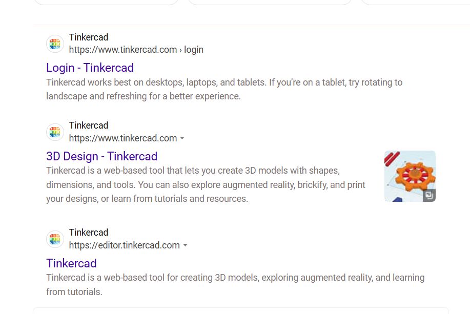
Websearch for TinkerCAD
Interface of TinkerCAD
TinkerCAD is not just only for designing circuits, we can also use it to design 3D models and many inbuilt examples are available in the website
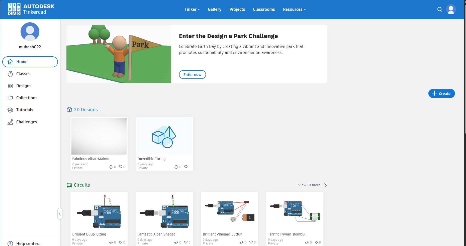
TinkerCAD
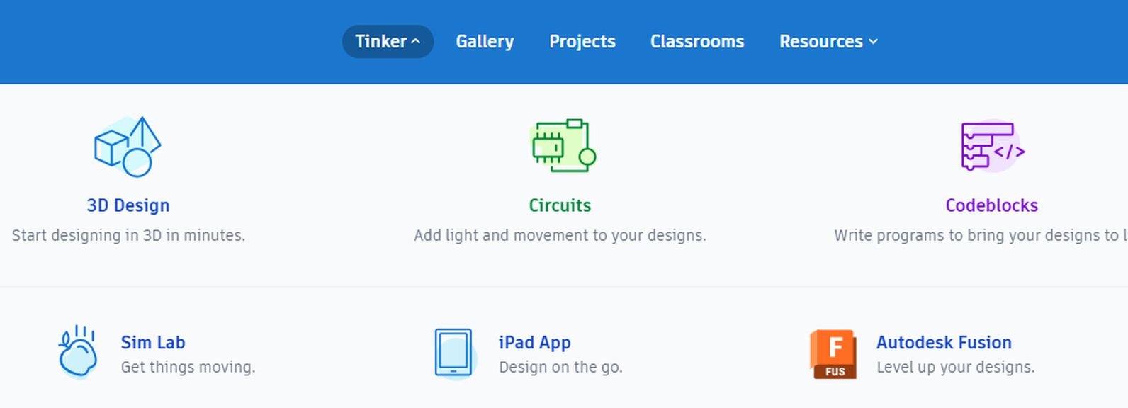
Differnet usage of TinkerCAD
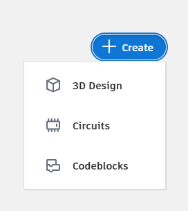
Let's Create a new circuit for our Assignment
Click on the Circuits button below
Step 1:
Navigation bar in KiCAD
- Clipboards
- Rotation of components
- Delete
- Undo
- Redo
Navigations

Control Bars
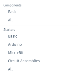
Components Selection Area
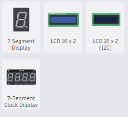
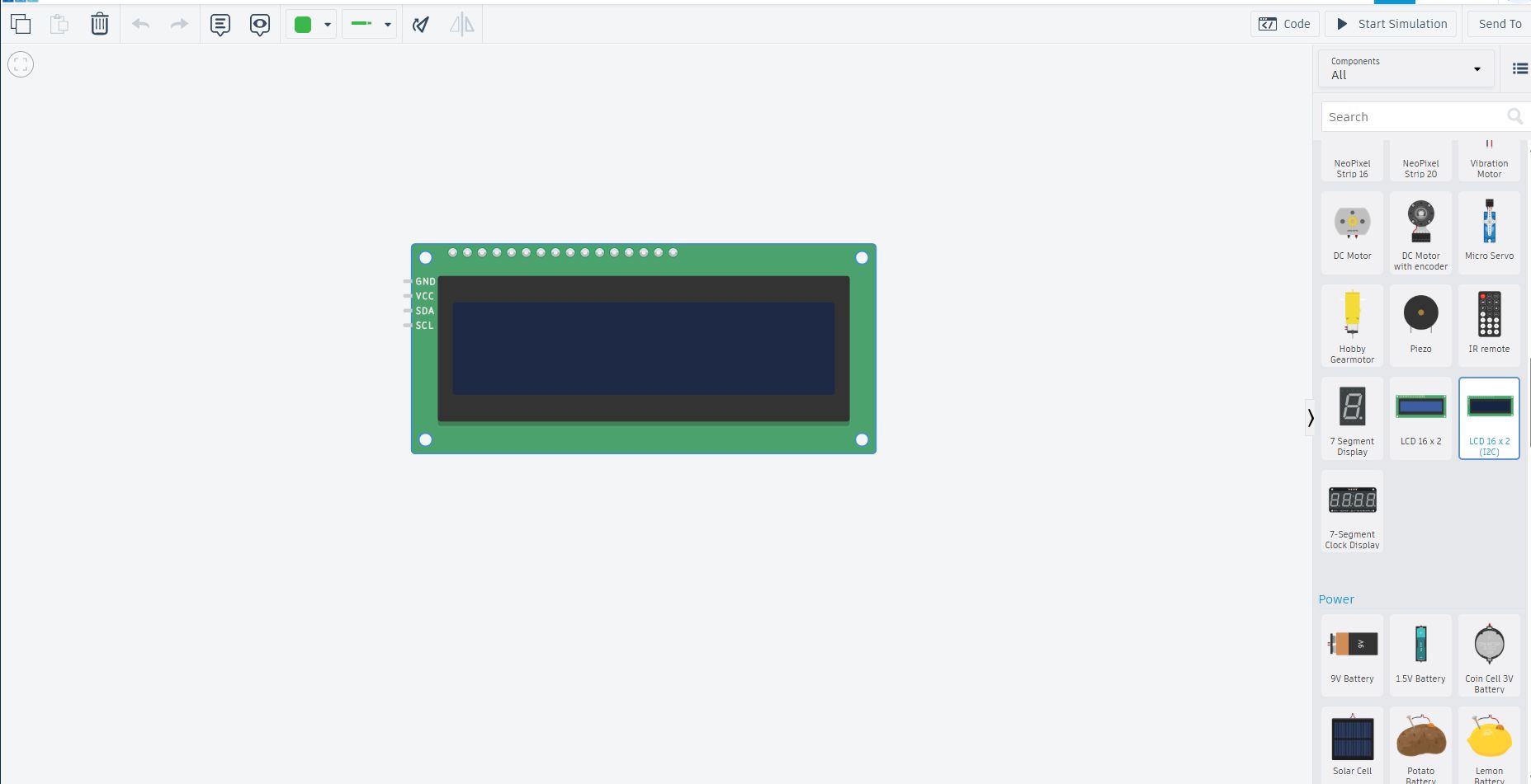
Various Display availability in TinkerCAD
Step 2:
For this Week, we are gonna work on LCD Display so Choosing 16*2 LCD display
Various Display availability in TinkerCAD
Arduino LCD 16x2 Display Guide
This guide explains how to display "Welcome to Fab Academy" on a 16x2 LCD using an Arduino and the Adafruit_LiquidCrystal library.
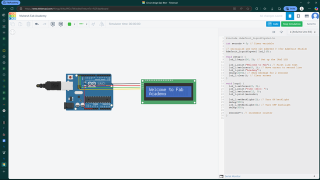
16x2 LCD Display with Arduino
This image shows a 16x2 LCD Display connected to an Arduino, demonstrating basic display functionalities.
Now let's dive into to development process
1. Hardware Requirements
- Arduino Board (Uno, Mega, etc.)
- 16x2 LCD Display
- I2C Module (PCF8574T)
- Connecting Wires
- External Power Source (if needed)
2. Wiring Instructions
| LCD Pin | Arduino Pin |
|---|---|
| VCC | 5V |
| GND | GND |
| SDA | A4 (Uno) / 20 (Mega) |
| SCL | A5 (Uno) / 21 (Mega) |
3. Arduino Code
            #include <Adafruit_LiquidCrystal.h>
            int seconds = 0;
        Adafruit_LiquidCrystal lcd_1(0);

        void setup() {
            lcd_1.begin(16, 2);
            lcd_1.print("Welcome to Fab");
            lcd_1.setCursor(0, 1);
            lcd_1.print("Academy");
            delay(2000);
            lcd_1.clear();
            }

        void loop() {
            lcd_1.setCursor(0, 0);
            lcd_1.print("Time (sec): ");
            lcd_1.setCursor(11, 0);
            lcd_1.print(seconds);

            lcd_1.setBacklight(1);
            delay(500);
            lcd_1.setBacklight(0);
            delay(500);

            seconds++;
        }
Arduino Code Explanation – LCD with Timer
Libraries and Variables
#include <Adafruit_LiquidCrystal.h>
int seconds = 0;
Adafruit_LiquidCrystal lcd_1(0);
- #include <Adafruit_LiquidCrystal.h>: Adds the library needed to control the LCD using I2C or other interfaces.
- int seconds = 0;: Creates a variable to count and display time in seconds.
- Adafruit_LiquidCrystal lcd_1(0);: Creates an LCD object called
lcd_1. The parameter0is used when only one LCD is connected.
setup() Function
void setup() {
  lcd_1.begin(16, 2);
  lcd_1.print("Welcome to Fab");
  lcd_1.setCursor(0, 1);
  lcd_1.print("Academy");
  delay(2000);
  lcd_1.clear();
}
- lcd_1.begin(16, 2);: Initializes the LCD with 16 columns and 2 rows.
- lcd_1.print("Welcome to Fab");: Prints text on the first line of the LCD.
- lcd_1.setCursor(0, 1);: Moves the cursor to the beginning of the second line.
- lcd_1.print("Academy");: Prints "Academy" on the second line.
- delay(2000);: Waits for 2 seconds (2000 milliseconds).
- lcd_1.clear();: Clears the LCD screen.
loop() Function
void loop() {
  lcd_1.setCursor(0, 0);
  lcd_1.print("Time (sec): ");
  lcd_1.setCursor(11, 0);
  lcd_1.print(seconds);

  lcd_1.setBacklight(1);
  delay(500);
  lcd_1.setBacklight(0);
  delay(500);

  seconds++;
}
- lcd_1.setCursor(0, 0);: Places the cursor at the beginning of the first line.
- lcd_1.print("Time (sec): ");: Displays the label "Time (sec):" on the LCD.
- lcd_1.setCursor(11, 0);: Moves cursor to the 12th column of the first line.
- lcd_1.print(seconds);: Displays the current value of
seconds. - lcd_1.setBacklight(1);: Turns ON the LCD backlight.
- delay(500);: Waits for half a second.
- lcd_1.setBacklight(0);: Turns OFF the LCD backlight.
- delay(500);: Waits again for half a second, creating a blinking effect.
- seconds++;: Increases the second counter by 1 every second.
What This Code Does
This Arduino code displays a welcome message ("Welcome to Fab Academy") for 2 seconds, then starts counting time in seconds. The LCD backlight blinks every 0.5 seconds to create a visual effect while the time increases.
Learning Summary
- Understand the basics of Arduino and its components.
- Understand about the Xiao - Seeed Studio Esp32C3
- Learn how to use the LiquidCrystal library to control an LCD screen.
- Implement a simple timer using the LCD screen.
OLED Display Experiment
After understanding the communication protocols and validating the circuit in TinkerCAD, I implemented the project physically using an Arduino Uno and a 0.96-inch SSD1306 OLED display. The objective was to establish I²C communication and display custom text on the OLED screen. This experiment helped me understand how embedded systems communicate with external display devices and present information in real time.
OLED Working Principle
OLED stands for Organic Light Emitting Diode. Unlike traditional LCD displays, OLED displays do not require a backlight because each pixel emits its own light. This results in better contrast, lower power consumption, and excellent visibility. The SSD1306 OLED used in this assignment has a resolution of 128 × 64 pixels and communicates using the I²C protocol through only two signal lines: SDA and SCL.
Circuit Connections
The OLED display was connected to the Arduino Uno using the I²C communication interface. The connections used are shown below.
| OLED Pin | Arduino Uno Pin | Function |
|---|---|---|
| VCC | 5V | Power Supply |
| GND | GND | Ground |
| SDA | A4 | Serial Data Line |
| SCL | A5 | Serial Clock Line |
Libraries Used
To communicate with the OLED display, the following Arduino libraries were used:
| Library | Purpose |
|---|---|
| Wire.h | Provides I²C communication support. |
| Adafruit_GFX.h | Provides graphics functions such as text, lines, and shapes. |
| Adafruit_SSD1306.h | Controls the SSD1306 OLED display module. |
Code Explanation
The program begins by including the required libraries for I²C communication and OLED control. The display object is then initialized with a resolution of 128 × 64 pixels. Inside the setup function, communication with the OLED display is established and the display is initialized. In the main loop, the display buffer is cleared, the cursor position is set, and the text "WELCOME TO ACADEMY!" is written to the screen. Finally, the display buffer is updated so that the text becomes visible on the OLED screen.
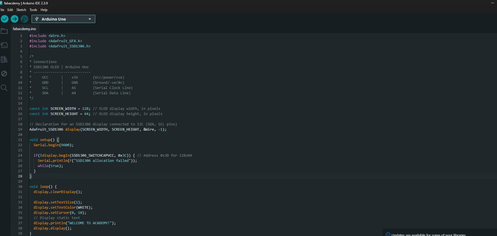
Arduino IDE showing the SSD1306 OLED display program.
Hardware Demonstration
After successfully uploading the program, the OLED display initialized correctly and displayed the programmed text. The experiment verified successful I²C communication between the Arduino Uno and the SSD1306 OLED display module.
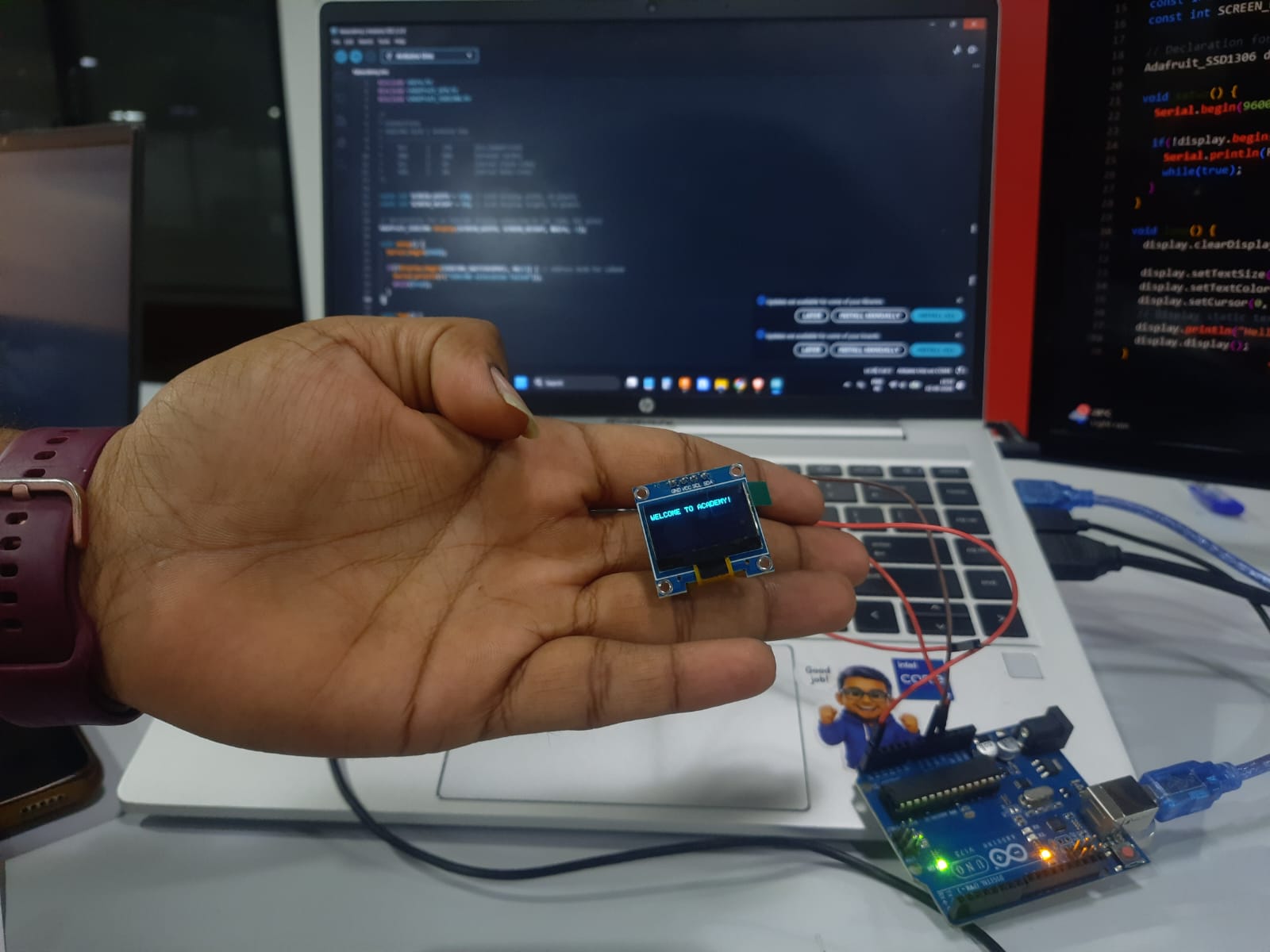
Physical implementation of the OLED display experiment using Arduino Uno and SSD1306 OLED module.
Learning Outcome
Through this experiment, I gained practical experience in interfacing an OLED display with a microcontroller using the I²C communication protocol. I learned how external libraries simplify hardware interaction, how display modules are initialized, and how embedded software can be used to present information on graphical displays. This activity strengthened my understanding of hardware-software integration in embedded systems.
Downloads and References
The following resources were used throughout this week's Embedded Programming assignment. These references include the microcontroller documentation, development board documentation, and the Arduino source code used for the OLED display experiment.
| Resource | Description | Link |
|---|---|---|
| Arduino Uno Datasheet | Official technical documentation for the Arduino Uno development board. | View Datasheet |
| XIAO ESP32-C3 Documentation | Hardware specifications, pinout, and programming guide. | View Documentation |
| OLED Display Source Code | Arduino sketch used to interface the SSD1306 OLED display using I²C communication. | Download Code |
Files Included
- Arduino Uno Datasheet
- XIAO ESP32-C3 Documentation
- SSD1306 OLED Arduino Program (.ino)
- Embedded Programming Assignment Documentation
These resources can be used to reproduce the experiment, understand the hardware architecture, and further explore embedded system development using Arduino and ESP32-based platforms.