Week 9: Input Devices
This week describes my understanding of how to use Input Devices. It also includes how to generate an analog output (PWM) using pin 9, how to use an oscilloscope and multimeter for analysis, and how to integrate different sensors with the microcontroller.
Objectives for the week
Interpret a Signal
We generate an analog output (PWM) using pin 9. A LED is connected to see the signal effect, and the oscilloscope and multimeter are used for analysis.
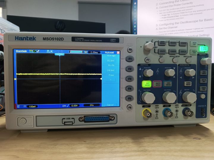
1. Understanding DSO Components
- Power Button: Turns the DSO ON/OFF.
- Display Screen: Shows the waveform.
- Probe Inputs (CH1, CH2): Connect the oscilloscope probes here.
- Time/Div Knob: Adjusts the time scale (horizontal axis).
- Volts/Div Knob: Adjusts the voltage scale (vertical axis).
- Trigger Controls: Helps stabilize the waveform.
2. Connecting the Oscilloscope to Arduino
A. Connect the Probe Correctly
- Turn OFF the oscilloscope before connecting anything.
- Take one oscilloscope probe and connect:
- Probe Tip: To Arduino PWM Pin 9 (or any analog pin you are testing).
- Probe Ground (Clip): To Arduino GND (Ground).
- Power up the Arduino and DSO.
3. Configuring the Oscilloscope for Basic Signal Viewing
A. Set the Channel
- Press the CH1 button to activate Channel 1 (where we connected the probe).
- If using two probes, press CH2 for the second channel.
B. Adjust the Voltage Scale (Vertical Setting)
- Use the Volts/Div knob to set the voltage range.
- Start with 1V/div and increase if needed.
- For a 5V Arduino signal, set it around 2V/div for better viewing.
C. Adjust the Time Scale (Horizontal Setting)
- Use the Time/Div knob to set the time range.
- If measuring PWM signals (~500Hz), start with 1ms/div.
- If measuring fast signals (above 1kHz), use 100µs/div.
D. Set the Trigger for a Stable Display
- Press the Trigger Menu and set:
- Mode: Edge
- Source: CH1
- Slope: Rising Edge
- Level: Adjust until the waveform stabilizes
4. Running the Oscilloscope & Viewing the Waveform
- Press AUTOSET (if available) to let the DSO automatically adjust settings.
- If AUTOSET doesn’t work well, manually tweak Volts/Div and Time/Div.
- Observe the waveform:
- If using PWM output, you should see a square wave.
- If using an analog sensor, the waveform may look more irregular.
- Use Cursors or Measurements (if your DSO has them) to check signal values.
5. Capturing & Analyzing the Waveform
- If your oscilloscope has a Save function, take a screenshot of the waveform.
- Compare the output with the expected Arduino signal.
- Adjust your Arduino code if needed to modify the signal.
                void setup() {
                pinMode(9, OUTPUT);
                }
                void loop() {
                    for (int u = 0; u < 255; u++){
                    analogWrite(9, u);
                    delay(50);
                    }
                }
Video Demonstration
Using a Multimeter to Measure Input Signals
In addition to observing signals using the oscilloscope, a digital multimeter was used to verify both digital and analog voltage levels generated by the input devices. Measuring the signal directly helps confirm that the sensor is producing the expected output before it is processed by the microcontroller.
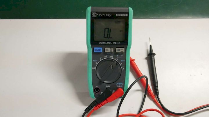
Measuring Digital Signals
The multimeter was set to DC Voltage mode. The black probe was connected to the GND pin and the red probe was connected to the signal output pin of the input device.
- Logic LOW State: Approximately 0 V
- Logic HIGH State: Approximately 3.3 V or 5 V depending on the device
These measurements confirmed that the input device was generating valid digital signals that could be detected by the microcontroller.
Measuring Analog Signals
For analog measurements, the multimeter remained in DC Voltage mode while the probes were connected between the analog output pin and GND. The voltage level changed continuously depending on the sensor condition.
- Minimum input condition produced a lower voltage level.
- Maximum input condition produced a higher voltage level.
- The changing voltage confirmed correct analog sensor operation.
The measured values matched the behavior observed in the serial monitor and oscilloscope, confirming that the input device was functioning correctly.
Learning Outcome
Through this activity, I learned how to use a digital multimeter to measure both analog and digital signals generated by input devices. I also learned how voltage levels correspond to logical HIGH and LOW states and how analog voltages can be verified before interfacing them with a microcontroller.