🖊️ FabTraceX
An Intelligent CNC Drawing Machine
A collaborative creation combining mechanical design, electronic integration, and AI-assisted automation. Built from repurposed 3D printer components and teamwork.
🔗 Explore Our Group Project – FabTraceX (Team G2)🤝 Team Members
Meet our team and the areas each member contributed to during the FabTraceX machine development.
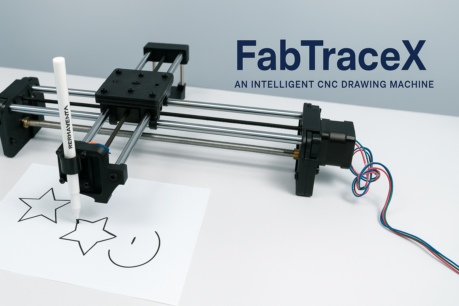
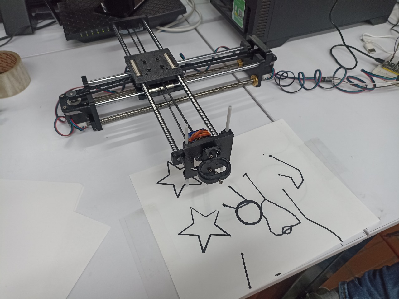
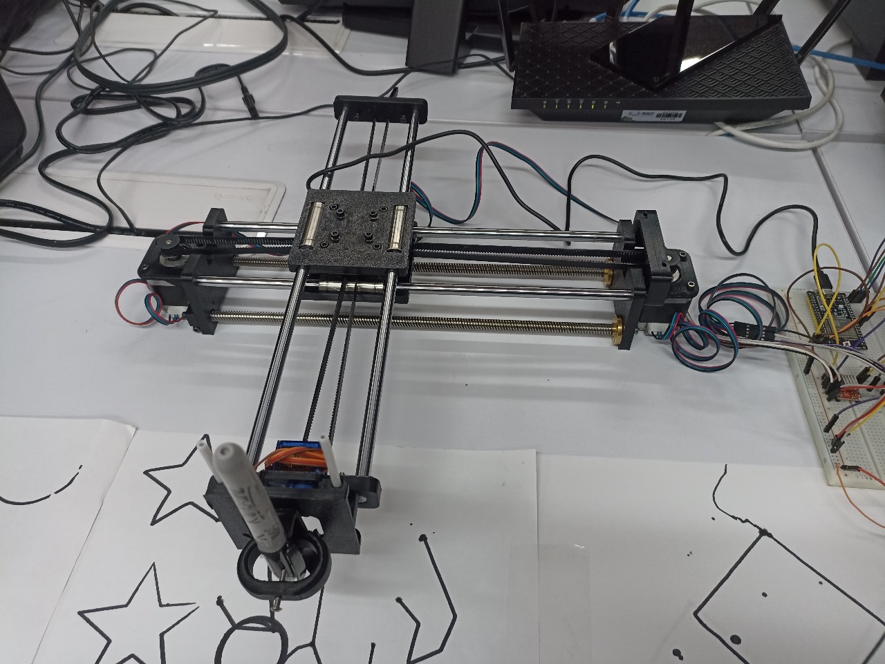
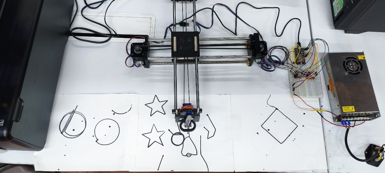
🖼️ Final machine with pen drawing mechanism in action.
🎥 Full demonstration video showing FabTraceX in motion.
🧠 Group Ideation and Planning
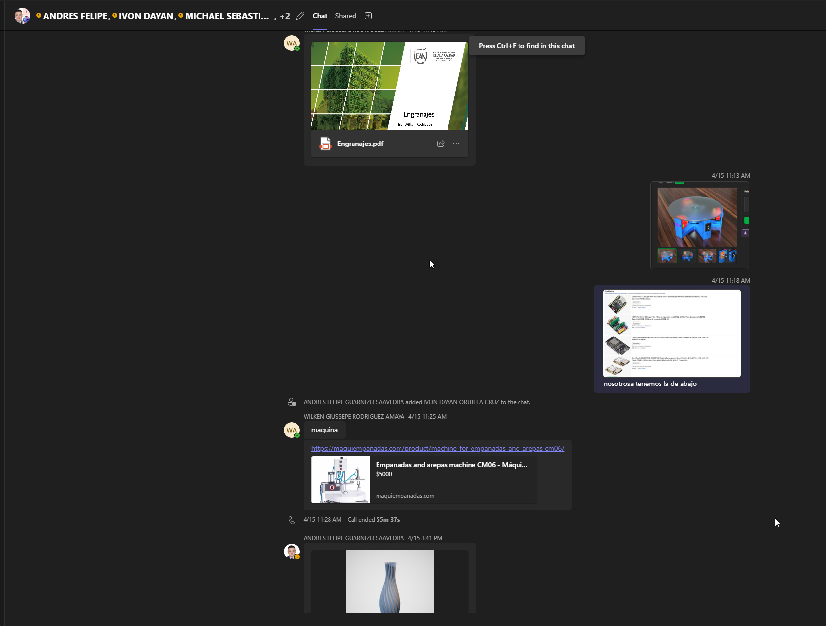
At the beginning of the assignment, our team held brainstorming sessions (both in-person and virtual) to explore what kind of machine we could build together. We evaluated different ideas—from a robotic claw machine to an empanada-making system. We chose based on what we could realistically make with recycled parts and what would be fun and educational to learn.
We looked at real examples to get inspired. Each option offered different possibilities and learning outcomes:
- Axidraw-inspired plotter: This project showed how to move a pen smoothly in two directions (X and Y) to create drawings. It helped us understand basic motion systems with belts and stepper motors, and it looked very achievable with recycled parts.
- Servo claw machine: A fun arcade-style machine that uses servo motors to open and close a claw. We liked its simplicity and compact frame, but realized it required a different type of precision control we weren’t ready to implement at that scale.
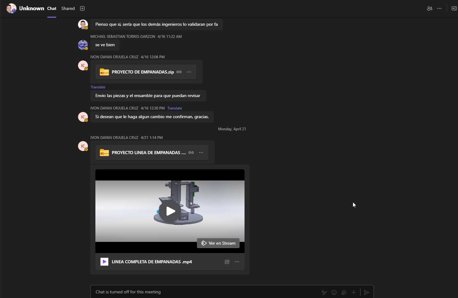
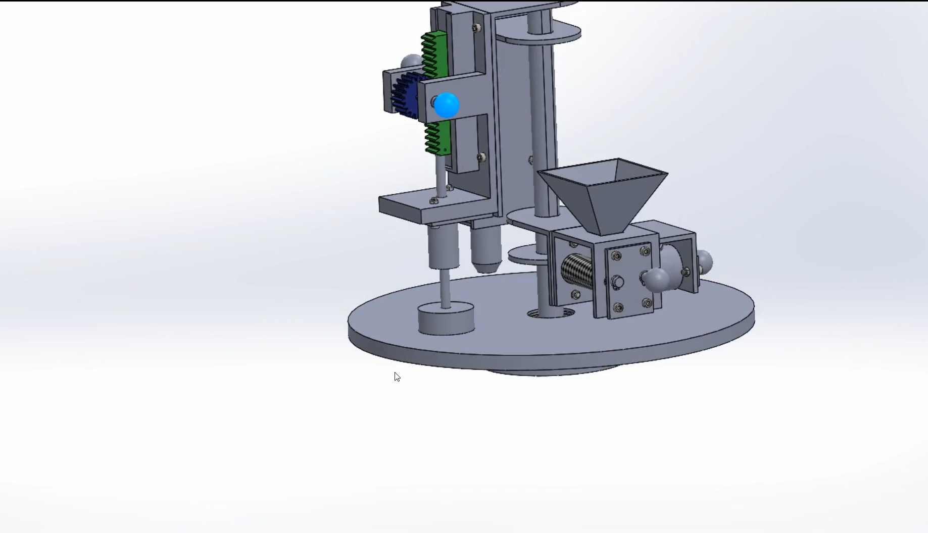
- CM06 Empanada and Arepa Machine: This was a real industrial reference. It uses molds and synchronized movement to press and form food. Although fascinating, it involved high mechanical pressure and mold precision that was hard to replicate with 3D-printed or salvaged parts.
✅ Final Decision: After several discussions and practical tests, we finally decided to create a 2-axis pen plotter-style drawing machine. This type of machine allows us to move a pen horizontally and vertically to draw patterns or designs automatically on a sheet of paper. We found it to be a perfect match for our skill level, timeframe, and available parts.
✨ To make the machine more interesting and dynamic, we planned to integrate a simple AI component that generates drawing paths. These paths are then interpreted by the machine to produce spontaneous, abstract line art. This added a creative twist to the functionality and helped us understand how digital instructions can be turned into physical motion. It's a small but valuable step toward merging mechanical design with code-based creativity.
To make the machine more interesting and dynamic, we planned to integrate a simple AI component that generates drawing paths. These paths are then interpreted by the machine to produce spontaneous, abstract line art. This added a creative twist to the functionality and helped us understand how digital instructions can be turned into physical motion. It's a small but valuable step toward merging mechanical design with code-based creativity.
Eventually, we chose to make a drawing machine using recycled parts from an Anycubic i3 Mega 3D printer. This machine was released around 2017 and became popular for its affordable price and decent print volume (210 x 210 x 205 mm). It included a touchscreen, filament sensor, and a solid metal frame, which made it stable during printing. However, by today’s standards, it is considered outdated. It lacks modern features like auto bed leveling, silent stepper drivers, and fast connectivity like Wi-Fi or cloud printing.
Despite being obsolete for precise 3D printing today, it offered a treasure trove of useful mechanical parts: aluminum extrusion frame, smooth rods, belts, pulleys, stepper motors, and even structural brackets. These made it a perfect donor machine for our FabTracex project. Instead of letting it go to waste, we decided to give it a new purpose by repurposing its skeleton and movement system for our drawing robot.
We considered this printer a great donor because it represented a type of machine that was once very popular but is now obsolete compared to modern printers with features like automatic leveling, touchscreens, silent drivers, and Wi-Fi control. By reusing it, we gave these materials a second life, learned how such a machine is built from the inside, and avoided waste.
I took the lead in carefully disassembling the printer, inspecting each component, and identifying what could be salvaged. Parts like belts, rails, and mounting brackets were sorted and later integrated into our new design.
We split the responsibilities: I focused on everything mechanical—taking things apart, testing fits, adjusting parts, and putting the machine back together. Michael designed the plastic parts we needed and printed them. Andrés worked on the electronics, writing the code and controlling the motors. We all gave feedback to each other and tested ideas together.
1️⃣ Component Recovery and Part Organization
Once we decided to build our drawing machine using parts from an Anycubic i3 Mega, my task was to carefully dismantle the printer and recover as many useful components as possible. I started by removing the outer casing and labeling all mechanical parts.
I organized the recovered parts into four main categories to make our design process easier:
- 🟢 Linear rods and shafts: These were in great condition and became the movement guides for the X and Y axes.
- 🟢 Belts and pulleys: Essential for movement transmission, most were still usable with minimal adjustment.
- 🟢 Screws, bolts, nuts, brackets: These allowed us to remount and adapt components without buying new hardware.
Each part was cleaned and tested manually. Damaged pieces (mostly plastic covers and outdated electronics) were discarded. I shared the list with Michael to help design new 3D printed brackets where needed. This phase was key to giving old parts a second life. I worked closely with him and Andrés throughout the recovery and adaptation process, constantly sharing observations, taking notes, and validating mechanical functionality together.
Note: All the electronics (like the mainboard and wiring) were removed. For this project, we used a new ESP32 board and other modern components handled by Andrés.
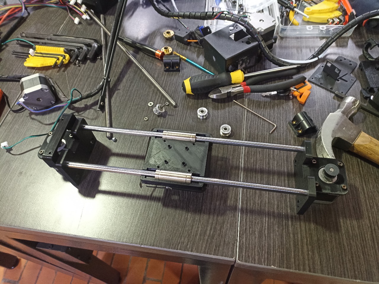
✅ Smooth rods carefully recovered and cleaned.
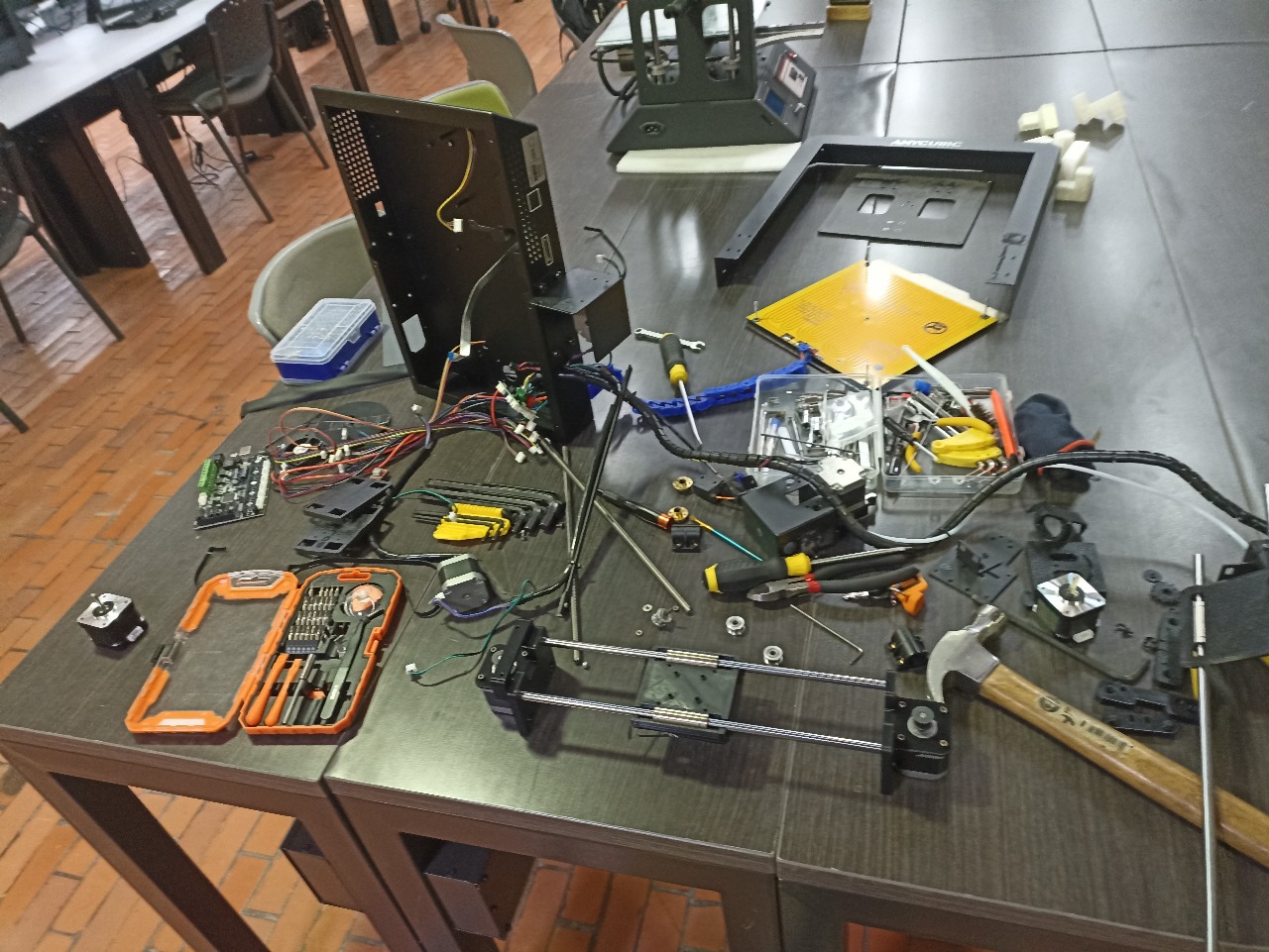
🧹 Overview of categorized components from the dismantled printer.
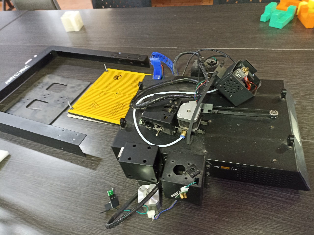
🛠️ Structural frame reused as the machine's new base.
2️⃣ Mechanical Assembly of the Drawing Machine
This phase reflects my core contribution to the team project, where I was in charge of the full physical assembly of the drawing machine. The process began once we had all the recovered components organized and the 3D printed parts designed by ready for fitting.
We worked as a coordinated team. While Michael prepared the CAD models and printed the brackets, I conducted the manual fit tests and structure setup. At the same time, was testing how the ESP32 and stepper drivers would integrate with our platform. We constantly exchanged feedback to make sure all mechanical elements were compatible with the electronic layout.
Specifically, I aligned the linear rods, installed the belts and pulleys, mounted the axis blocks, and tested the full X-Y movement manually. When we encountered friction or instability, I refined the parts by sanding, heating, or repositioning brackets until the motion felt smooth. I took special care with belt tension and symmetry to avoid cumulative misalignment.
To document the process and validate our build, we also captured short video clips of the motion system during initial testing. These clips show how we verified movement manually before connecting motors, and how we corrected alignment through hands-on troubleshooting.
We repeated tests with small load weights to simulate real drawing pressure and re-verified each structural axis before handing it off to Andrés for motor calibration. This level of teamwork allowed us to iterate fast and stay on the same page, both mechanically and electronically.
This section proves how we built the full mechanical base as a team: I was the assembler and adjuster, Michael was the modeler, and Andrés the integrator. Our workflow relied on constant communication and adaptation, demonstrating true collaborative machine building.
✅ Validation Checklist
- ✔️ Recovered rods, bearings and belts tested for alignment
- ✔️ Brackets and printed supports iteratively fitted and corrected
- ✔️ Belt tension manually adjusted and tested under simulated load
- ✔️ XY axes verified through manual travel tests
- ✔️ Movement validated before electronics were installed
🧩 Assembling the X and Y axes: Here we began fitting the salvaged rods into custom-printed supports. This photo shows the level of precision needed in alignment and symmetry for smooth motion.
⛓️ Belt and pulley setup: After aligning the rods, we mounted belts and pulleys, carefully adjusting their position to ensure stable tension and friction-free movement.
📐 Final frame check: This step confirmed the structural rigidity and alignment before integrating electronics, making sure all axes were square and balanced.
🎥 First movement test: In this test we checked manual travel without motors, evaluating mechanical resistance and initial tolerances.
⚙️ Smoothness verification: This repetition of the test helped identify subtle vibrations or slack in belts.
🔄 Real-time tuning: Here we actively adjusted belt tension and repositioned parts during motion testing.
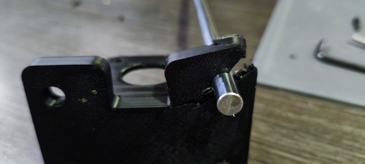
❗ The first 3D printed bracket had measurement issues. I worked with Michael to correct the CAD file and reprint the part for proper rod fitting, showing how we resolved design-to-physical mismatches together.
3️⃣ Tools & Techniques
The mechanical build process for FabTraceX was much more than simply assembling parts — it was about solving problems with creativity, discipline, and the right tools. Each phase required me to evaluate conditions, adjust methods, and adapt pieces in real time. I approached this challenge using a variety of traditional tools, modern measuring devices, and fabrication support from our teammate Michael for 3D printed parts.
- 🔧 Basic hand tools: Screwdrivers, Allen keys, and pliers were used constantly to mount, align, and correct elements like shafts, brackets, and supports.
- 📏 Digital caliper: Absolutely essential for ensuring proper distance between axes and rod positioning — even small deviations caused friction or slippage.
- 🔥 Heat gun: Used on several occasions to soften PLA parts slightly and press them into final positions without breaking or cracking.
- 📐 Level and ruler: Important for visually confirming horizontal axis integrity and equal height before electronics were installed.
- 🪛 Bench clamps and sanding paper: When parts didn’t align, I gently sanded surfaces or clamped them during curing or tightening.
My method wasn’t always perfect. Some parts had to be tested two or three times before they worked well. For example, I discovered that belt pulleys aligned only after small vertical adjustments to the base blocks. These were not failures — they were learning moments. I now understand why mechanical tolerances matter so much and how to fix them manually when needed.
Collaborating with Michael was key. He helped me modify the 3D models on-the-fly based on real measurements I made. In one case, a rod wouldn’t insert because the internal diameter of a support was slightly off — Michael updated the STL, printed a new one, and we solved it in one iteration. This workflow was fast, dynamic, and efficient.
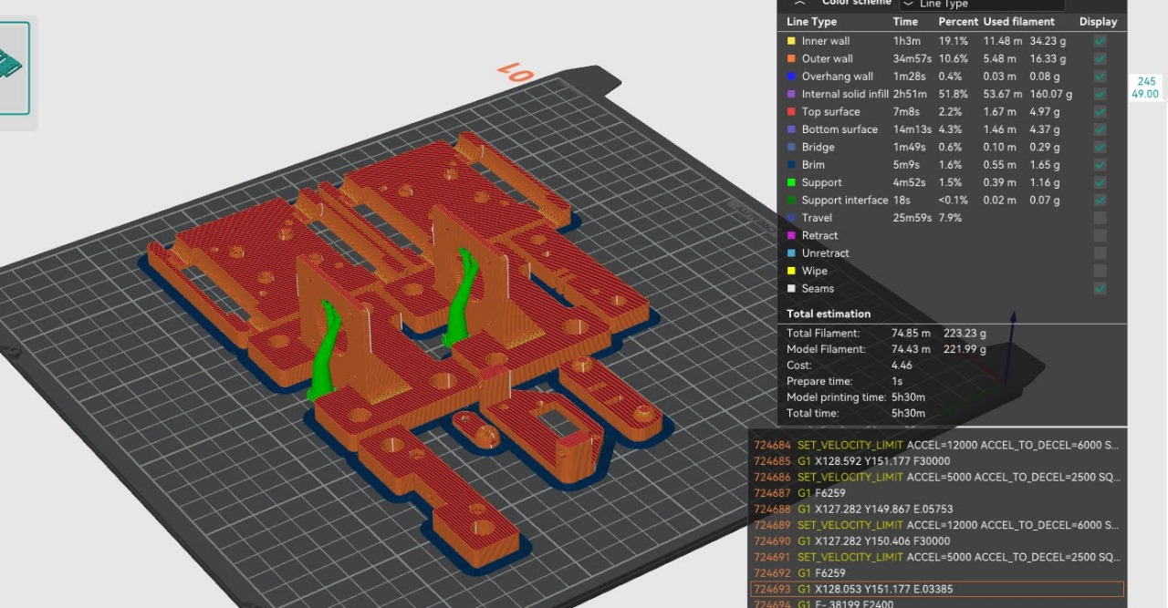
🖨️ Collaborative workflow with Michael: checking slicing orientation and validating dimensions.
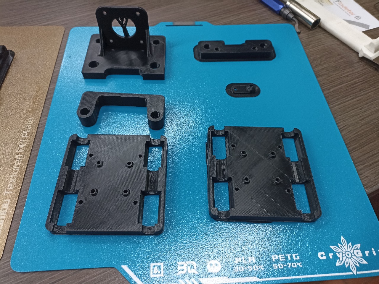
🔩 Freshly printed components that passed my fit and movement tests before full assembly.
In summary, this section helped me solidify a crucial principle of fabrication: the right tools don’t just build — they correct, adapt, and guide. And when those tools are in your hands, every decision you make has a direct physical consequence. That’s powerful learning.
🔚 Final Reflections – Mechanical Assembly
This week marked a turning point in my Fab Academy journey. I was responsible for the mechanical disassembly, recovery, and reconstruction of our drawing machine. Working with real physical parts — not just simulations or models — pushed me to think critically, adapt constantly, and collaborate intentionally.
One of my biggest challenges was recovering parts from a discarded 3D printer without damaging them. Some pieces were misaligned, some were fragile, and others had to be reinforced or redesigned. With Michael's support, I tested and corrected the mechanical design, iterating printed parts until everything fit as intended.
Throughout the process, I learned that prototyping is not perfect from the start. Brackets didn’t fit, rods didn’t move smoothly, belts slipped. These were not failures — they were checkpoints that helped us improve. Through sanding, reshaping, and testing, I made sure our base was strong and precise, allowing Andrés to integrate the electronics effectively.
This taught me how real-world mechanics behave. Unlike Fusion or simulation tools, physical materials introduce friction, flexibility, error — and opportunity. That made this process not only technical, but deeply human.
Looking ahead, I want to explore stronger mounting designs, modular structures, and maybe even AI-assisted mechanical correction tools. I leave this week with calloused hands, a machine that moves, and the confidence that I can build — not just digitally, but physically.
🔗 Also see: Michael's Week 12 | Andrés' Week 12