Assignments
Group Assignment:
- Do your lab’s safety training.
- Characterize your lasercutter’s focus, power, speed, rate, kerf, joint clearance
and types.
- Document your work to the group work page and reflect on your individual page what
you learned.
Individual Assignments:
- Design, lasercut, and document a parametric construction kit, accounting for the
lasercutter kerf, which can be assembled in multiple ways.
- Cut something on the vinyl cutter.
Week 3. Computer-Controlled Cutting
Reflection on Group Work and Personal Learning
This week, the group work allowed me to dive deep into the laser cutter, adjusting
parameters such as power, speed, focus, and joint clearance. I learned how important it
is to calibrate the machine well and properly adjust these parameters to achieve precise
cuts. I also understood how factors like kerf or mirror cleanliness can affect the
results.
The most valuable part of this group work was the exchange of knowledge with my
teammates. Through collaboration and joint testing, I was able to learn from their
experiences and apply best practices to adjust the cutter’s parameters. This
collaborative approach helped me improve my technical skills and gain a deeper
understanding of the challenges we face when working with computer-controlled cutting
technology.
However, there were also challenges. One of the main ones was ensuring that all team
members consistently followed safety and calibration protocols. There were some
variations in the results due to errors in the calibration process or incorrect
parameter adjustments. These problems taught us the importance of strictly following
procedures to guarantee optimal results and avoid risks during the cutting process.
In summary, this group work provided me with a clearer understanding of how to
efficiently and safely characterize and use a laser cutter. I learned that the key to
success in these processes lies in proper calibration, precise parameter adjustments,
and, above all, teamwork to share knowledge and continuously improve procedures. Without
a doubt, this learning will be fundamental for my future digital fabrication projects.
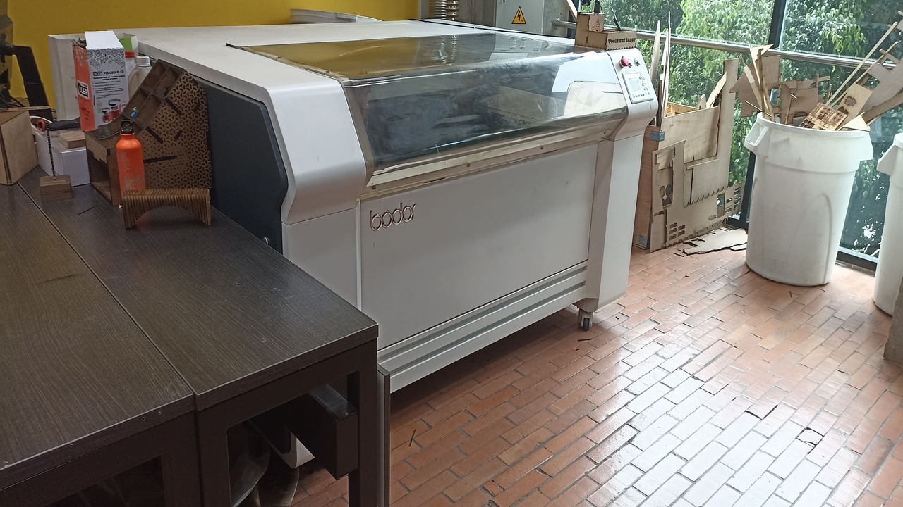
The machine I used this week
Bodoor CO₂ Laser Cutter
For this week’s assignment (Week 3), I used the Bodoor 150W CO₂ laser cutter, available at our FabLab. It’s a large, professional machine with a working area of 90 cm x 130 cm and adjustable height, which allows working with materials of different thicknesses.
It also has a rotary axis for engraving cylindrical objects, and a built-in camera that helps visualize the cutting area in real-time, which is very helpful when framing designs before cutting.
|
BODOOR LASER CUTTER
|
Material I used: 4mm MDF
I worked with 4mm MDF, the same material used in our group assignment. Based on our tests, I used the following configuration:
- Speed: 20 mm/s
- Min Power: 30%
- Max Power: 35%
- Kerf / Tolerance: -0.15 mm
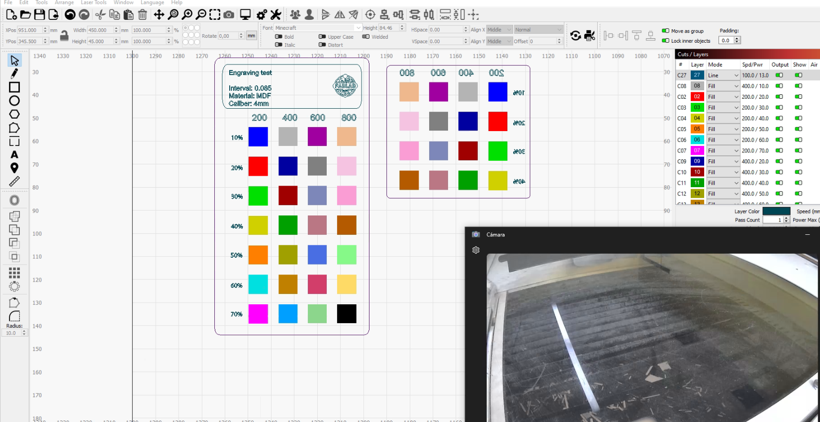
How to set power and speed in the software
In LightBurn software , you can easily configure the laser settings for each layer or object. You can choose between “Line” (for cutting) or “Fill” (for engraving), and assign different speeds and power levels to each one.
|
LAYER CONFIGURATION - LINE VS FILL
|
You can also adjust the order of layers, enable passes, and fine-tune the settings to get cleaner cuts or deeper engravings. These adjustments are made in the cut settings window, where each color in the design represents a different operation.
Tool layout and visual interface
One of my favorite features is the layout view inside LightBurn. You can clearly see the design placed on the work area and use the built-in tools to move, scale, or rotate elements. Below is a screenshot showing the workspace with available tools.
|
LIGHTBURN WORKSPACE WITH TOOLS
|
Live camera view
The Bodoor laser cutter also has a camera integrated into the lid. This camera shows the bed live inside LightBurn, which is extremely useful to frame your material, align your design, and monitor the cutting process while it’s happening.
|
CAMERA VIEW IN LIGHTBURN
|
Thanks to this camera feature, I could make small adjustments before cutting, avoid wasting material, and feel more confident during the operation.
All these tools and settings made the cutting process more precise and user-friendly. This setup is the one I’ll continue using for future assignments because it gives me great results.
Laser Cutter Safety and Parametric Kit Project
CO2 Laser Machine at Universidad EAN FabLab
At the FabLab of Universidad EAN in Colombia, we have this high-capacity, high-power machine. To learn more about the safety training, click on the following link CO2 Laser Machine.
Personally, I chose this machine to create my parametric kit using 4mm MDF. Thanks to the tests and trials carried out in the group, I obtained the correct configurations, speeds, power, and kerf to cut my design. Therefore, I proceeded to create my parametric kit.
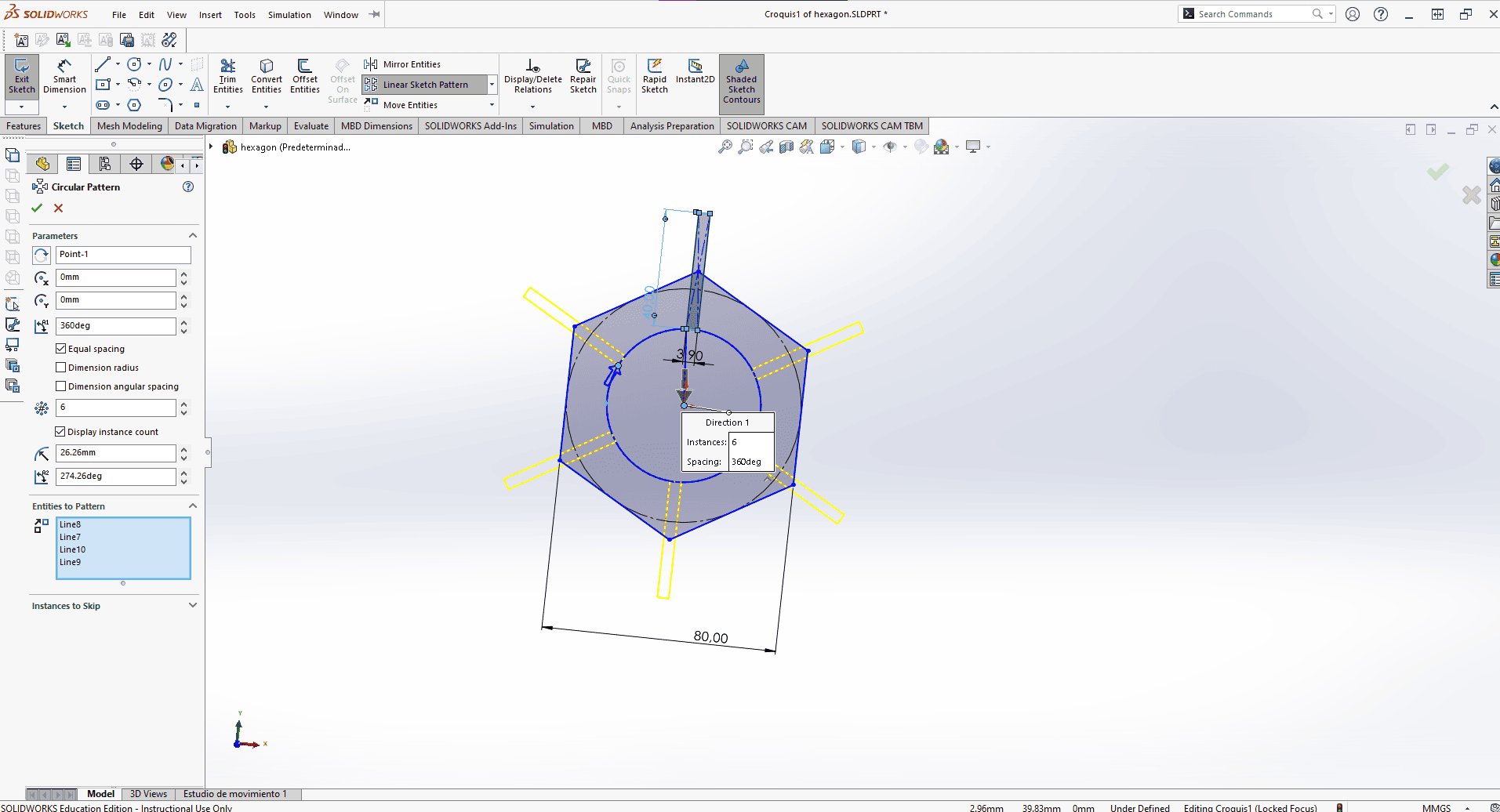
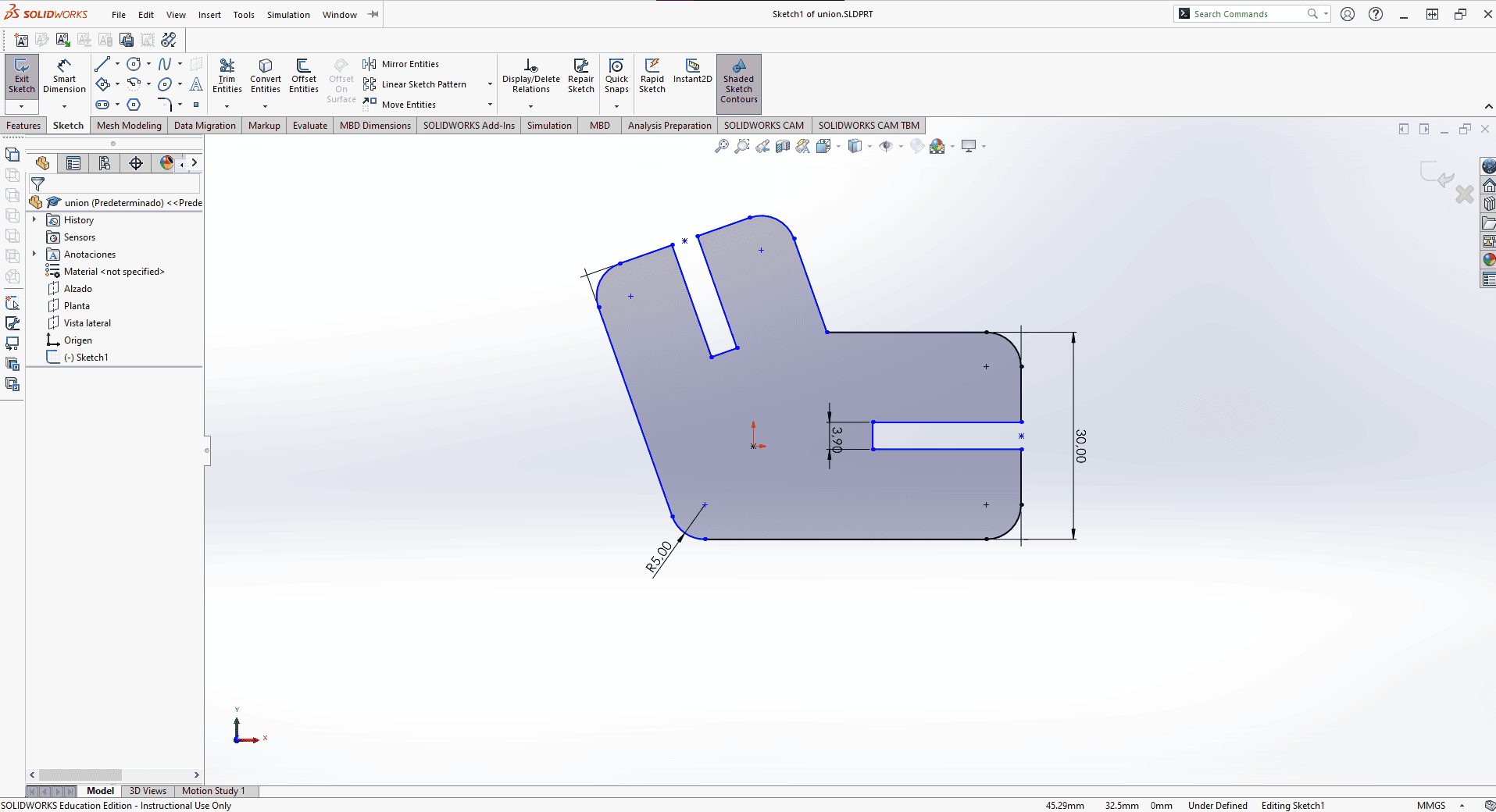
Parametric Kit in SolidWorks
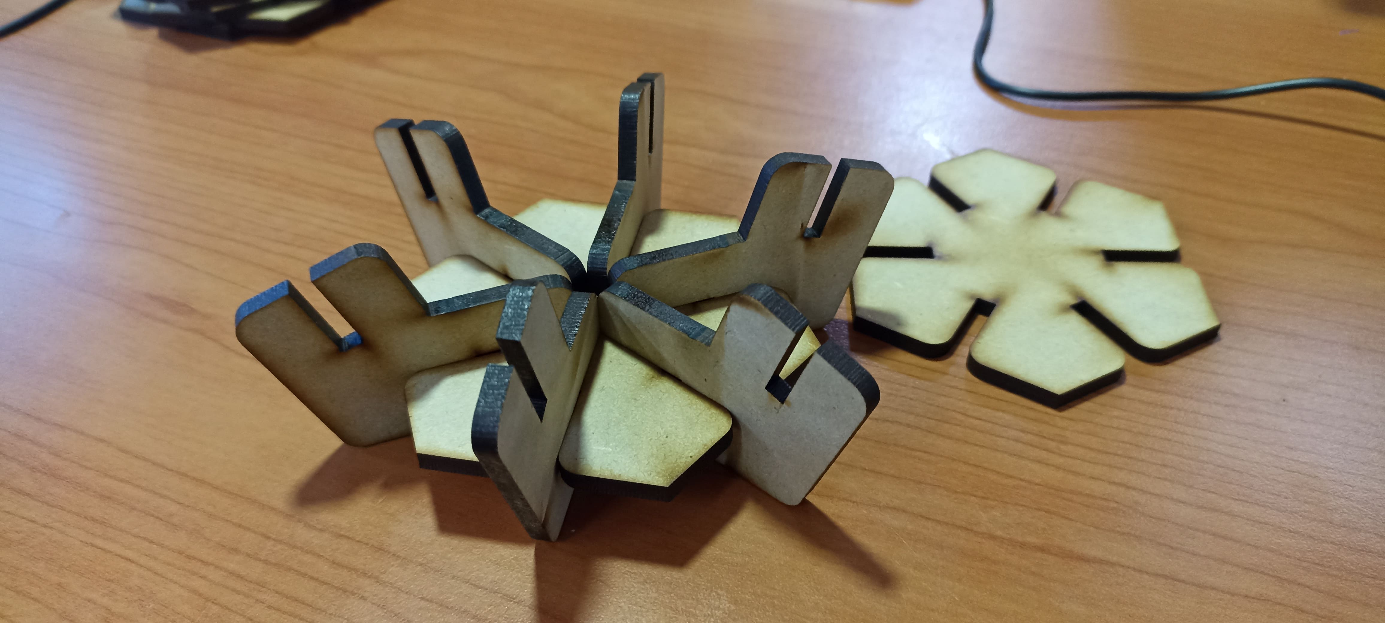
I evaluated two options to make the kit. One consisted of hexagonal pieces with many intersections. Why the hexagon? Because the mascot at my university is a bee, and this shape resembles a honeycomb — I wanted this inspiration reflected in my project.
|
HEXAGONAL DESIGN IDEA
|
It was quite simple since I relied on the variables found in Tools → Equations. I created a global variable to determine the wood thickness or the number of vertices I wanted for my piece.
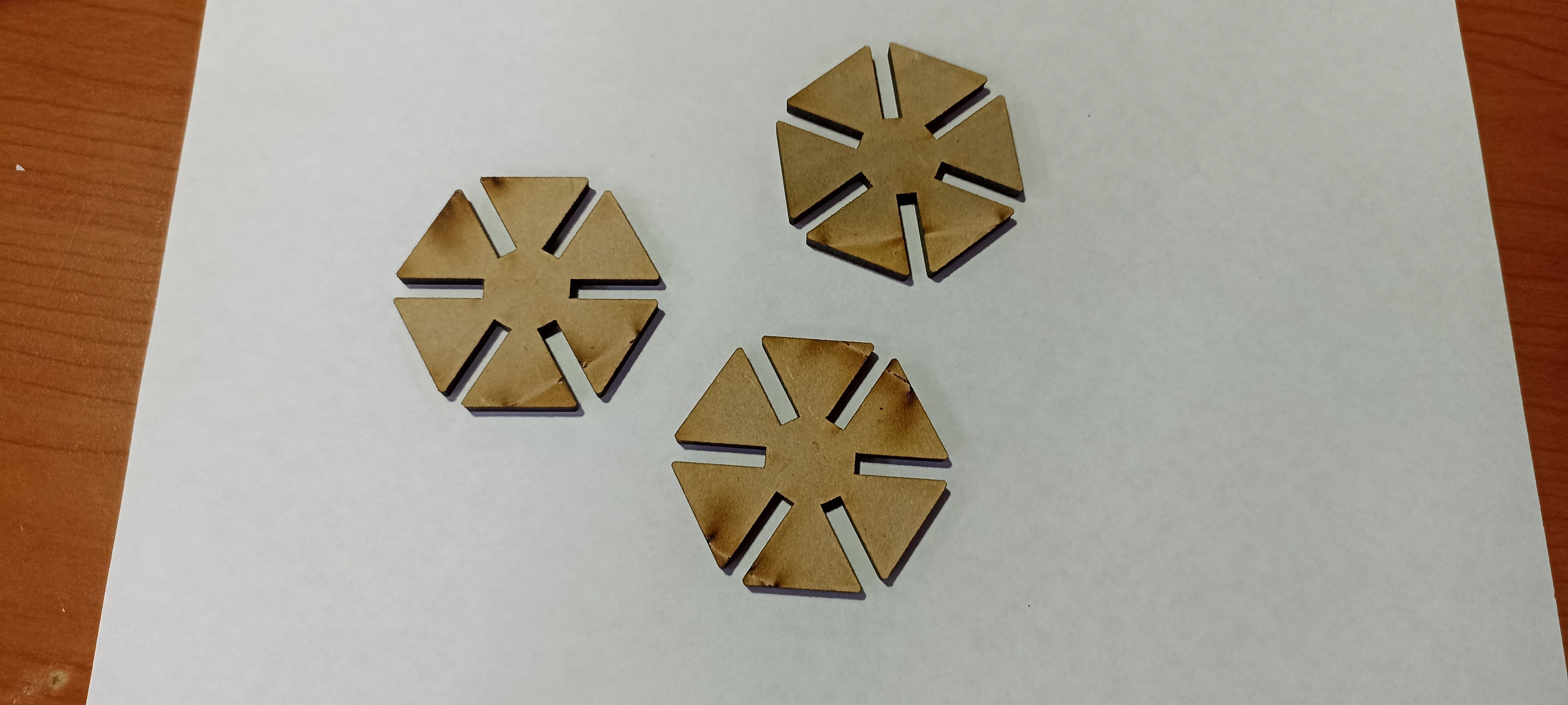
Then, I proceeded to cut them in the material.
|
LASER CUTTING VIDEO
|
However, I wasn't very satisfied with the result, so I decided to improve this kit. I felt it was incomplete and couldn't be used to build many things, no matter how hard I tried.
|
PIECES AND FIRST ASSEMBLY
|
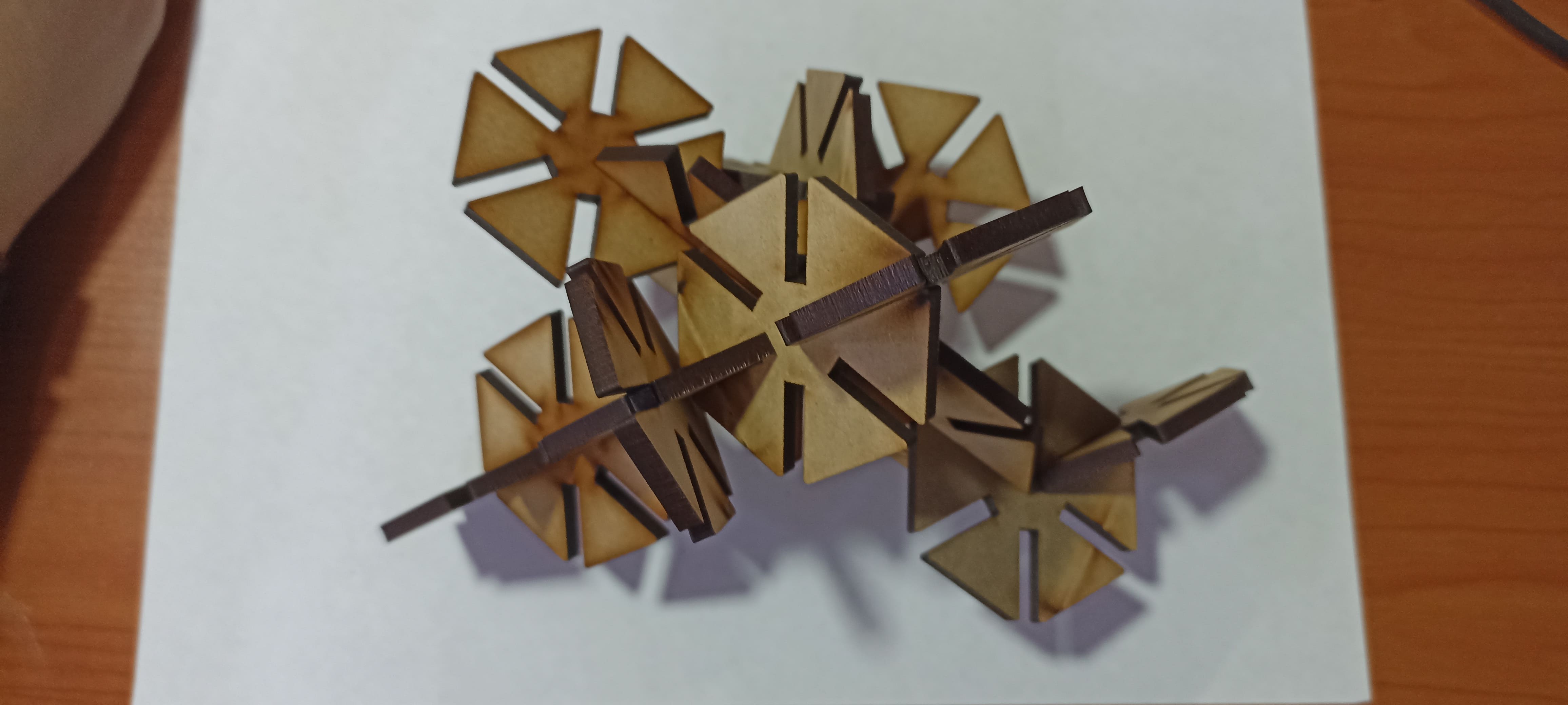
|
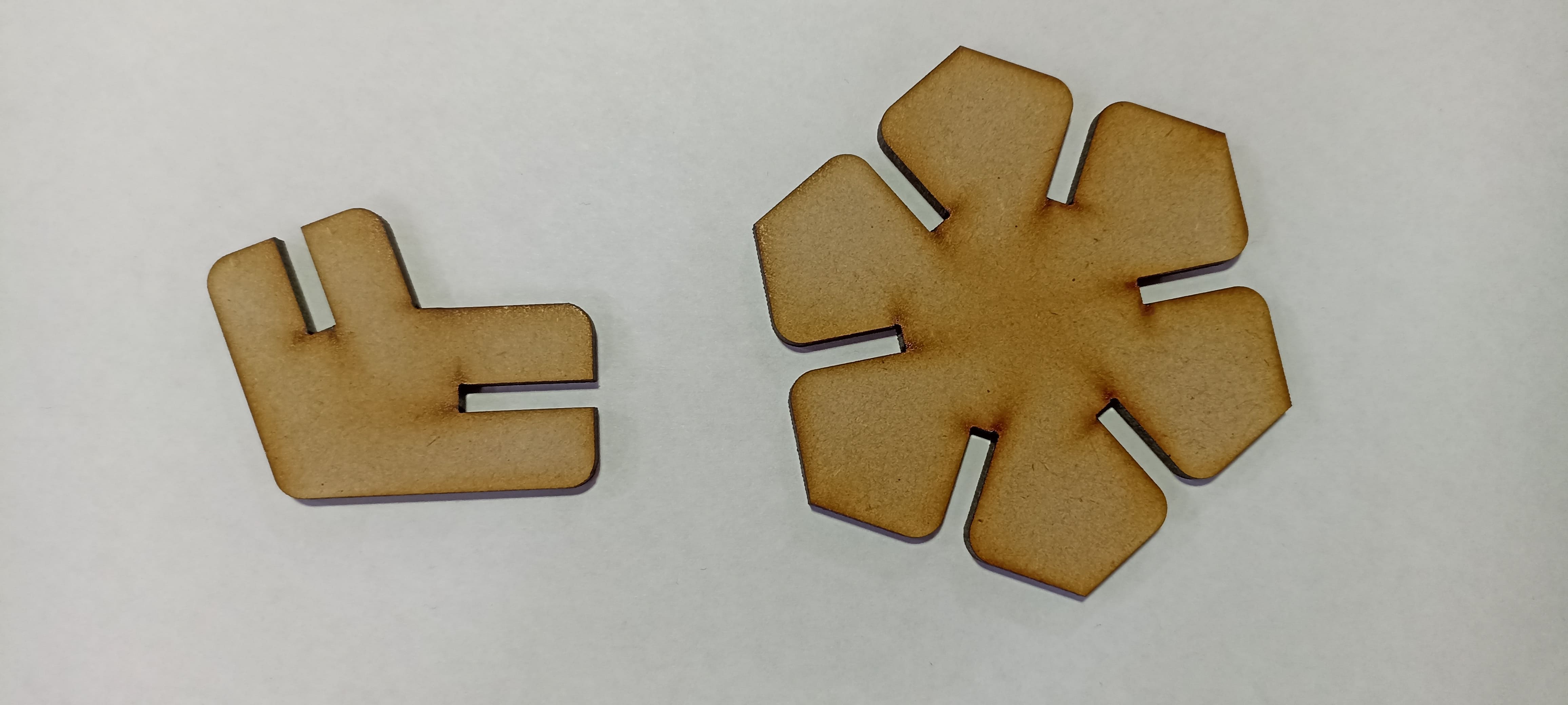
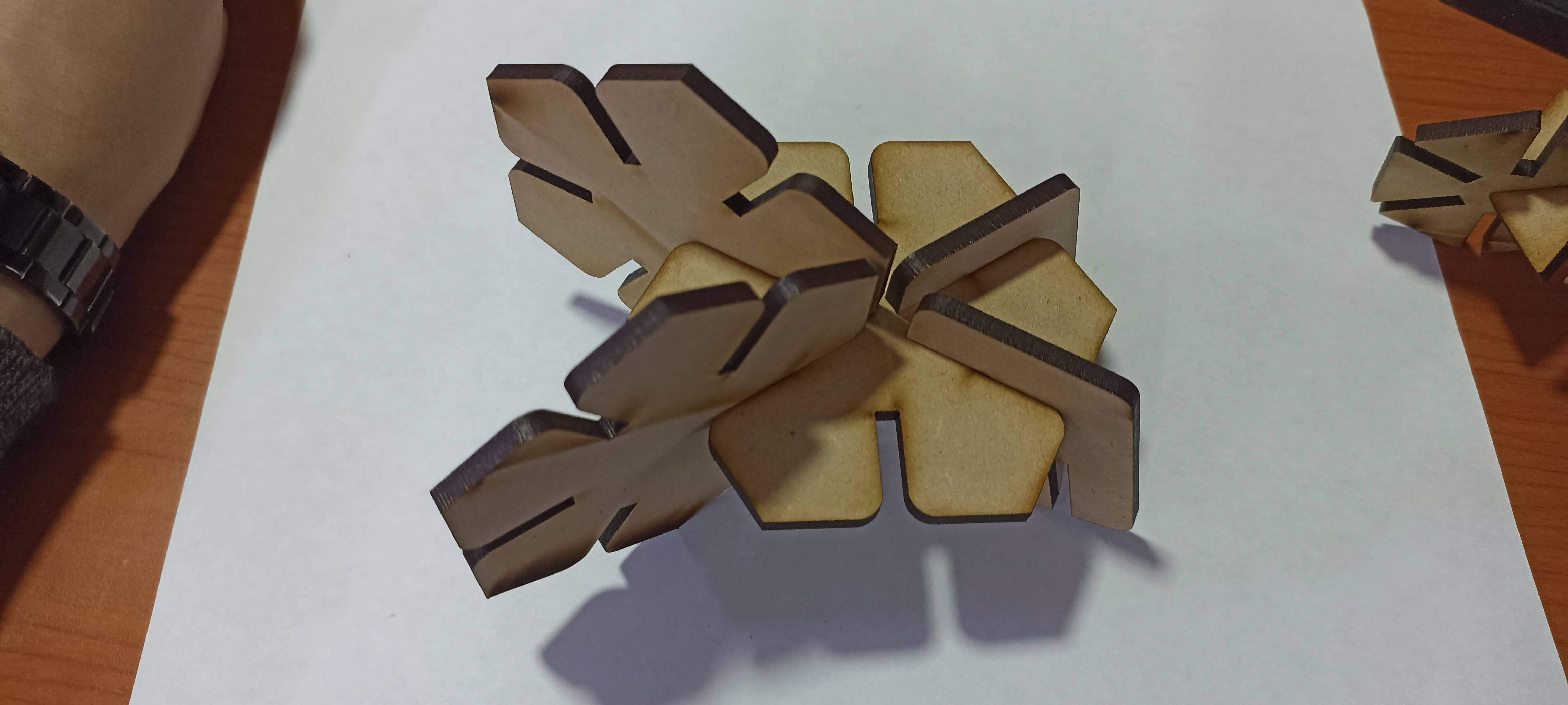
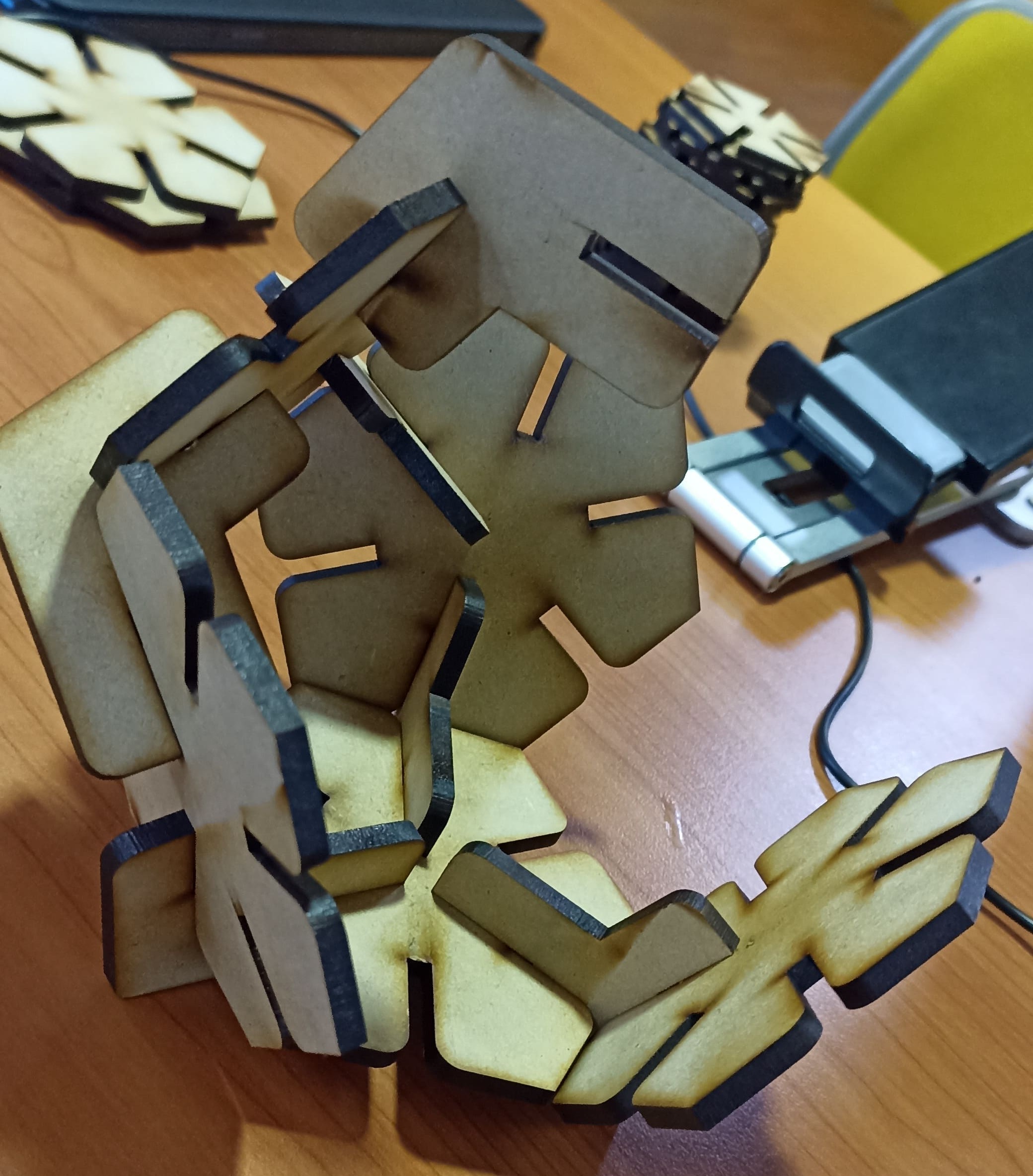
Therefore, I improved the design by adding curved edges (since I had poked myself on a corner during this process) and also designed a connecting piece that allowed me to create more assemblies.
|
IMPROVED PIECES
|
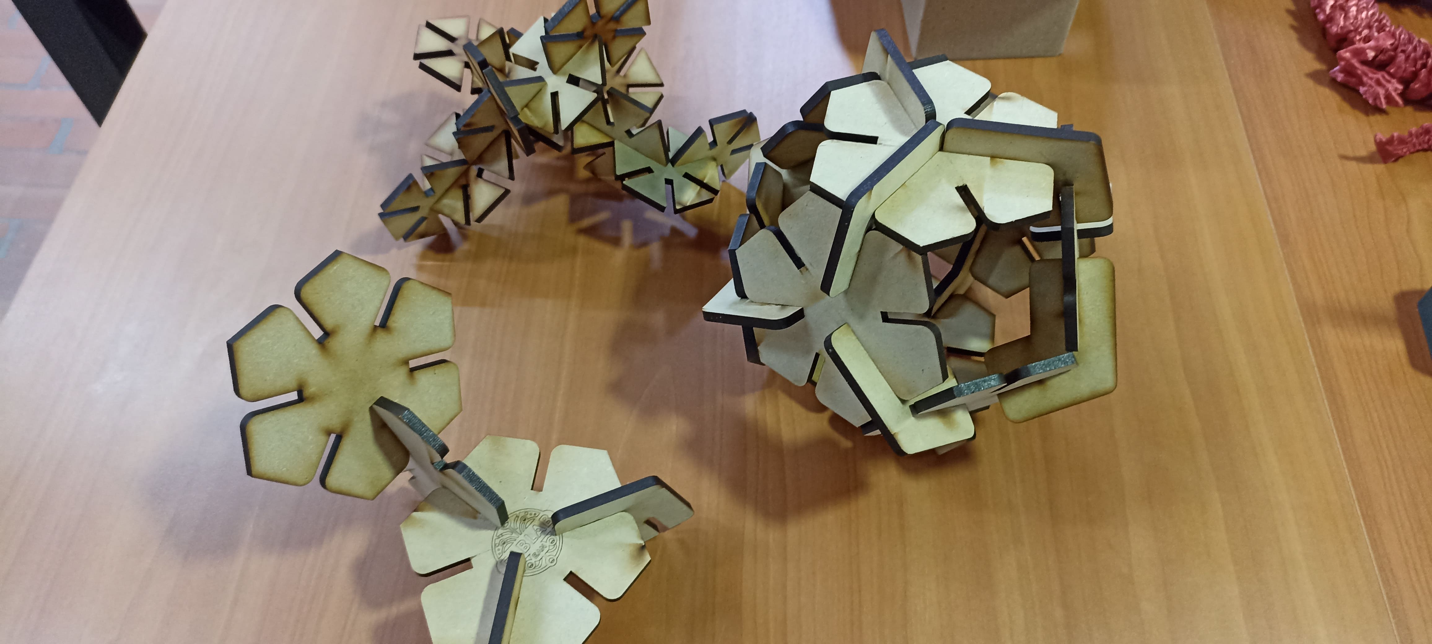
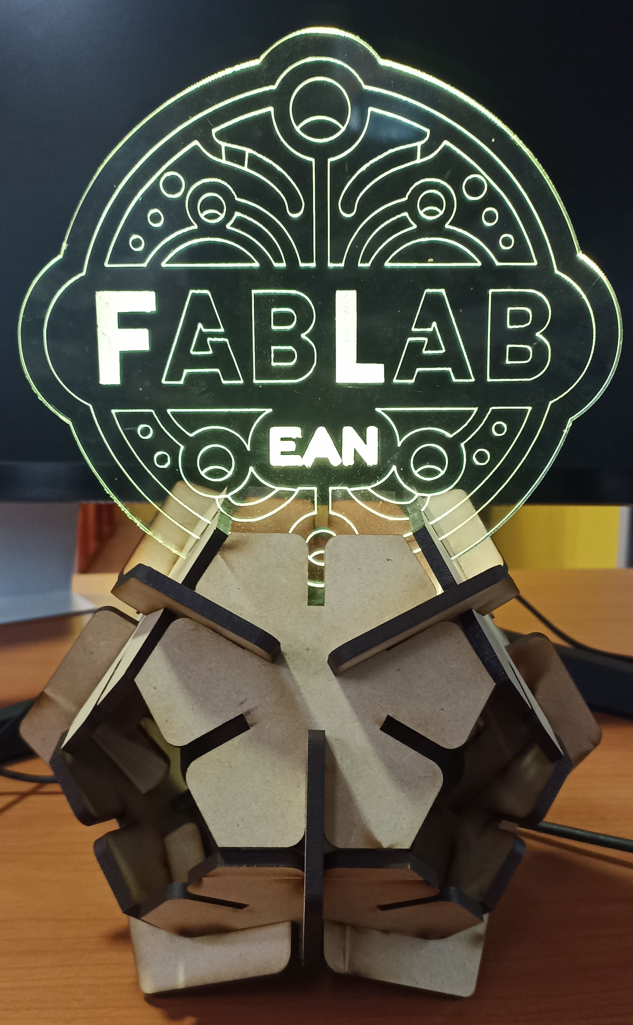
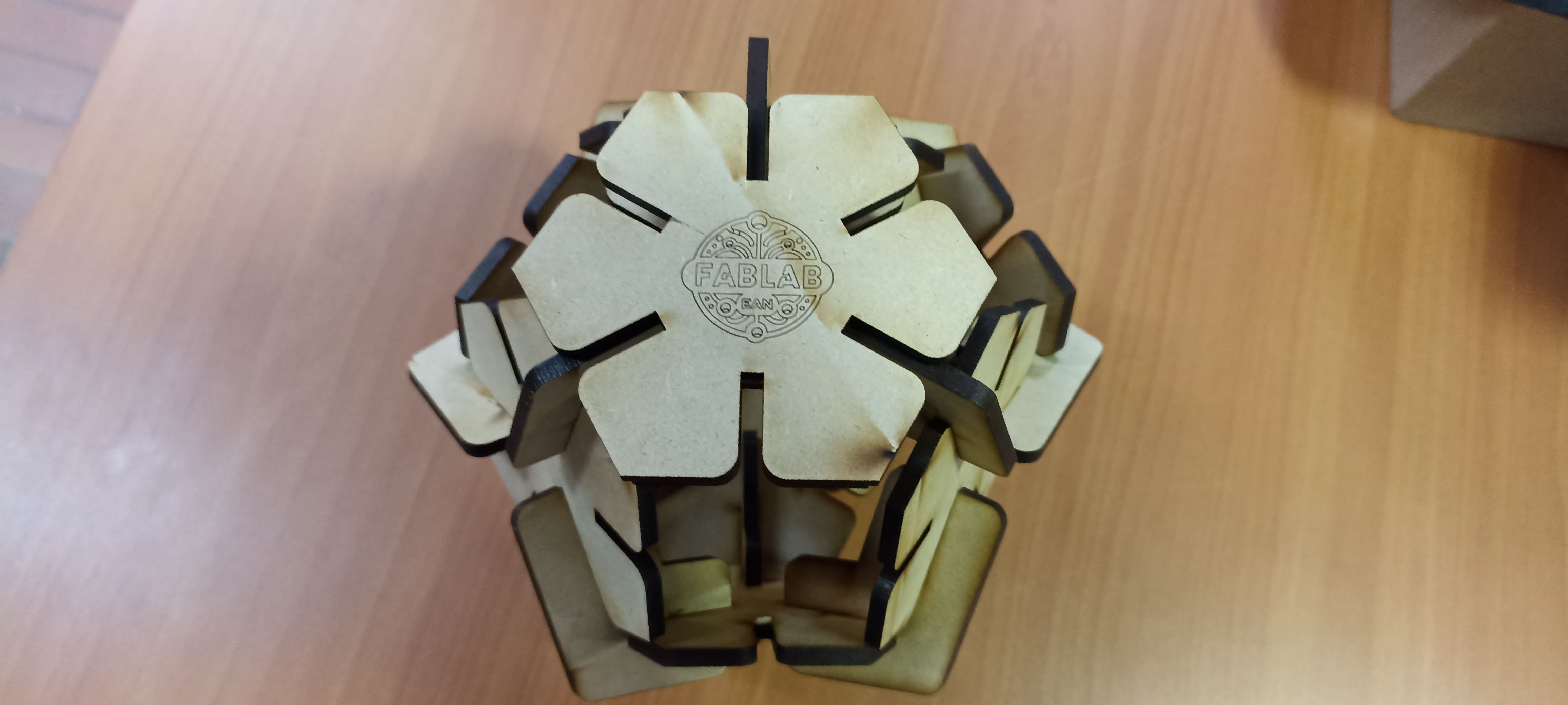
These new pieces allowed me to create different elements and structures. I built a chair, a table, something resembling an animal, and using many more of the joints and hexagons, I was able to create a volumetric piece, which I used to make a lamp.
Fiber Laser Engraving Process
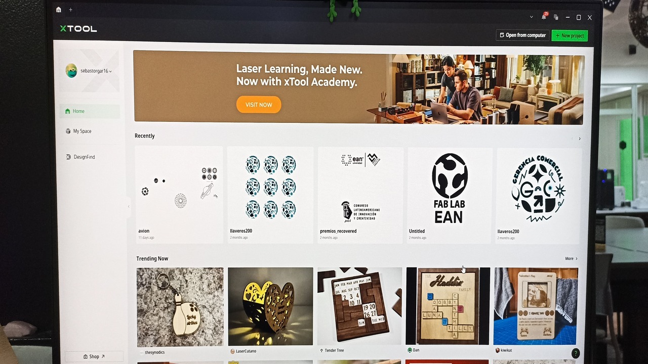
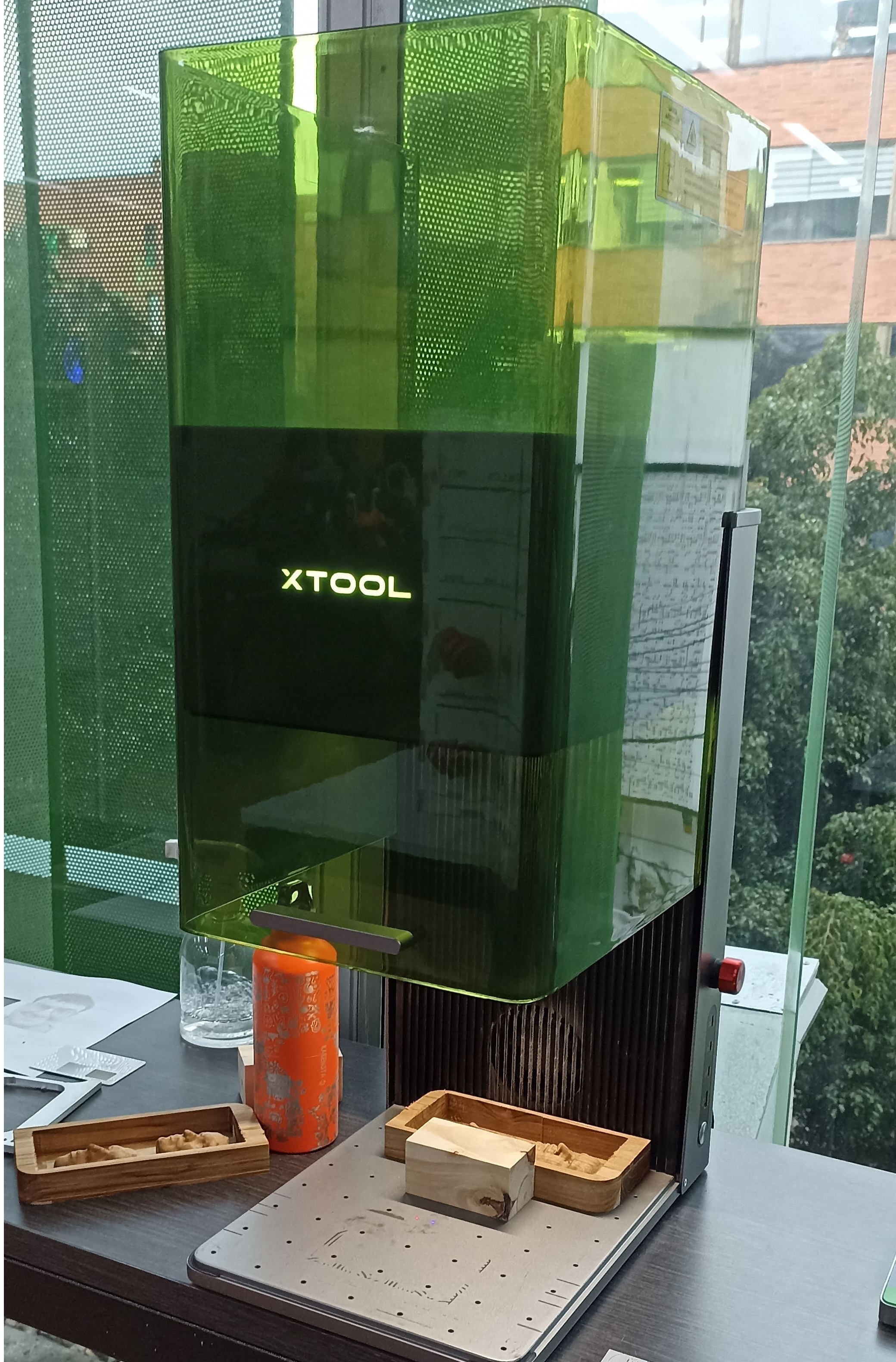
Introducing the F1 Ultra Fiber Laser Engraver
The F1 Ultra fiber laser engraver is a state-of-the-art machine available at our lab, designed for precision work on both metallic and non-metallic materials. This equipment stands out for its compact yet robust design, equipped with a high-quality laser head and an intuitive control interface. One of its most convenient features is the integrated XTools software, which provides Wi-Fi connectivity, allowing files to be transferred directly from a computer or mobile device without the need for physical connections.
|
XTOOLS SOFTWARE INTERFACE
|
This machine is versatile and can engrave materials such as steel, aluminum, leather, plastics, and wood. It’s a perfect tool for creative and technical projects that require fine detail and durability. Below is a look at the machine set up and the different materials I worked with during my project.
|
F1 ULTRA MACHINE PRESENTATION
|
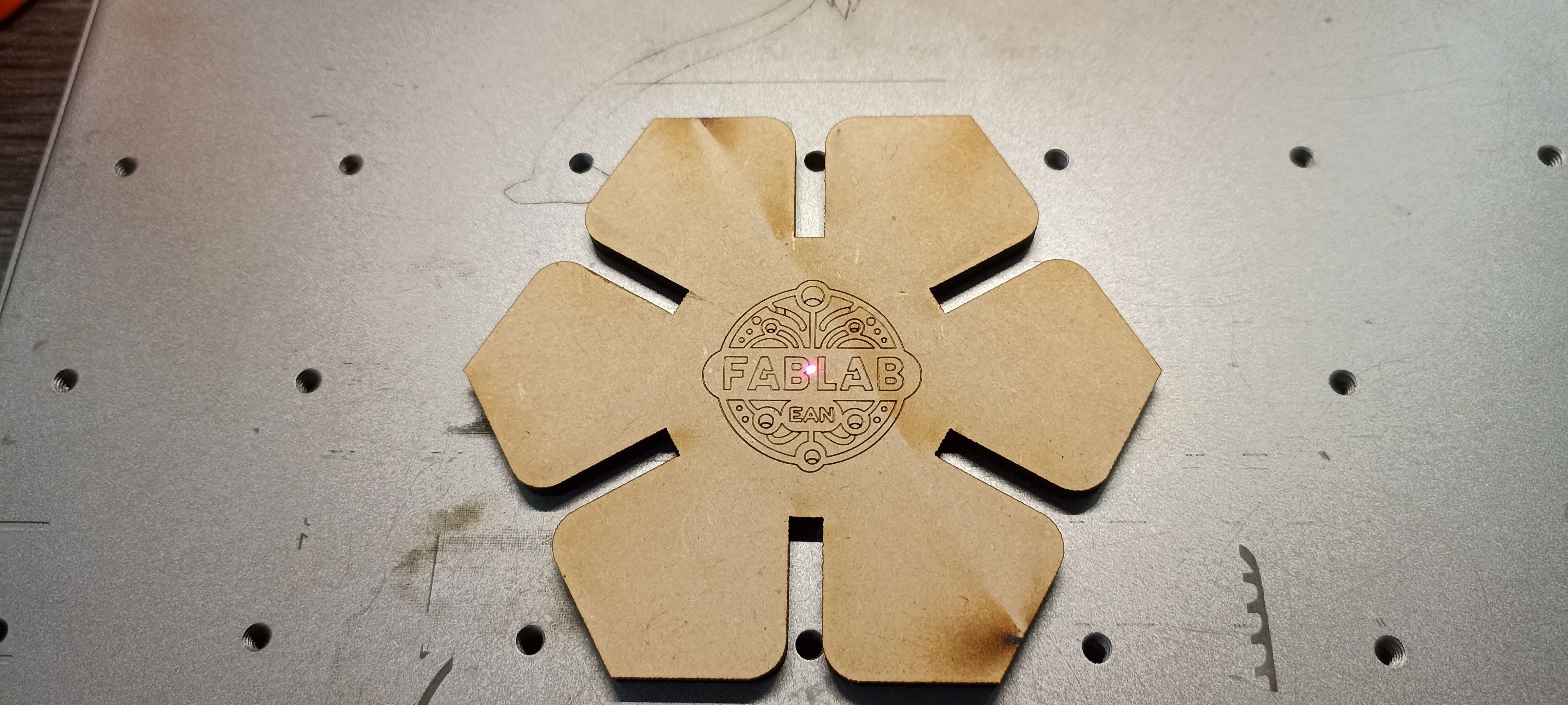
Engraving Process on MDF
I began by importing the FabLab university logo into XTools and preparing it for engraving on MDF. Before starting, I performed several small power and speed tests to determine the ideal settings and avoid burning the surface, as MDF is sensitive to excessive heat.
|
MDF HEXAGON ENGRAVED
|
|
PARAMETRIC KIT WITH ENGRAVED LID
|
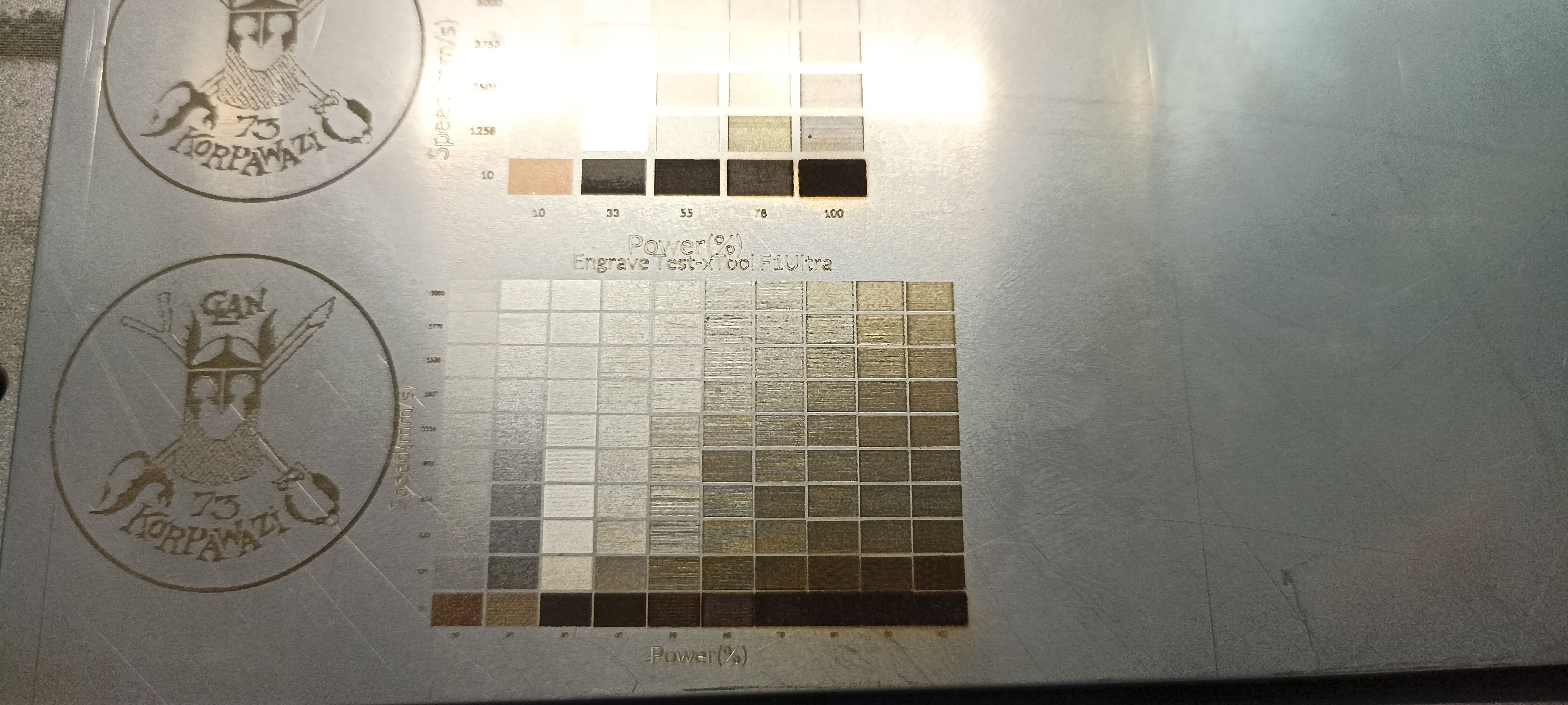
Engraving on Steel
Curious about the metal capabilities, I prepared a steel plate, carefully aligned it on the machine, and tested different power settings. Steel requires significantly higher power, so I ran several calibration tests to understand how the material reacts and to achieve the desired engraving effect.
|
STEEL IN THE MACHINE
|
|
POWER TESTS ON STEEL
|
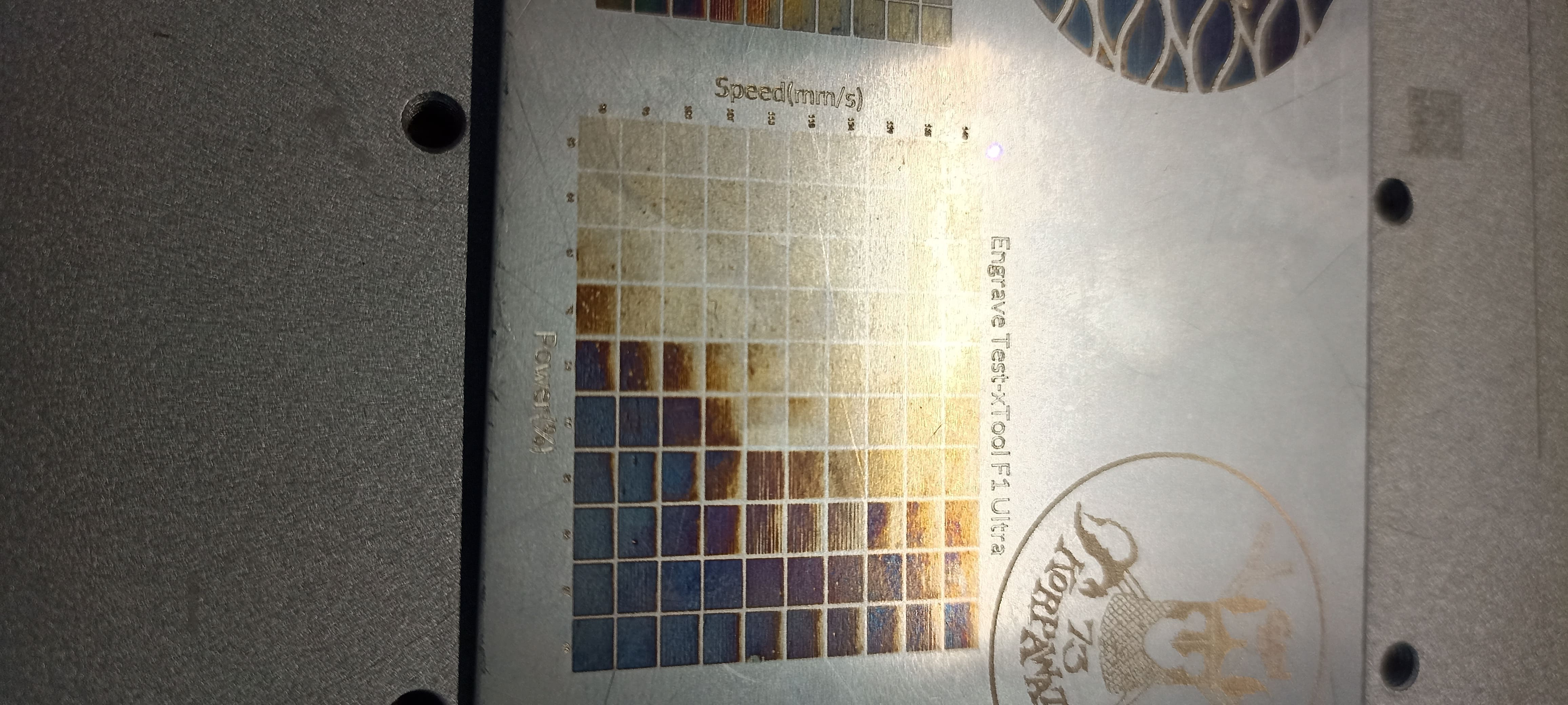
Additionally, I explored the UV laser functionality, which enabled me to create beautiful color effects on the steel surface, adding another layer of creative potential.
|
UV LASER CREATING COLORS ON STEEL
|
These combined experiments and careful calibrations resulted in high-quality, precise engravings that elevated the final look of both my metal and MDF projects, showcasing the incredible versatility of the F1 Ultra machine.
Vinyl Cutting
Machine used: Cricut Maker 3
Software: Cricut Design Space.
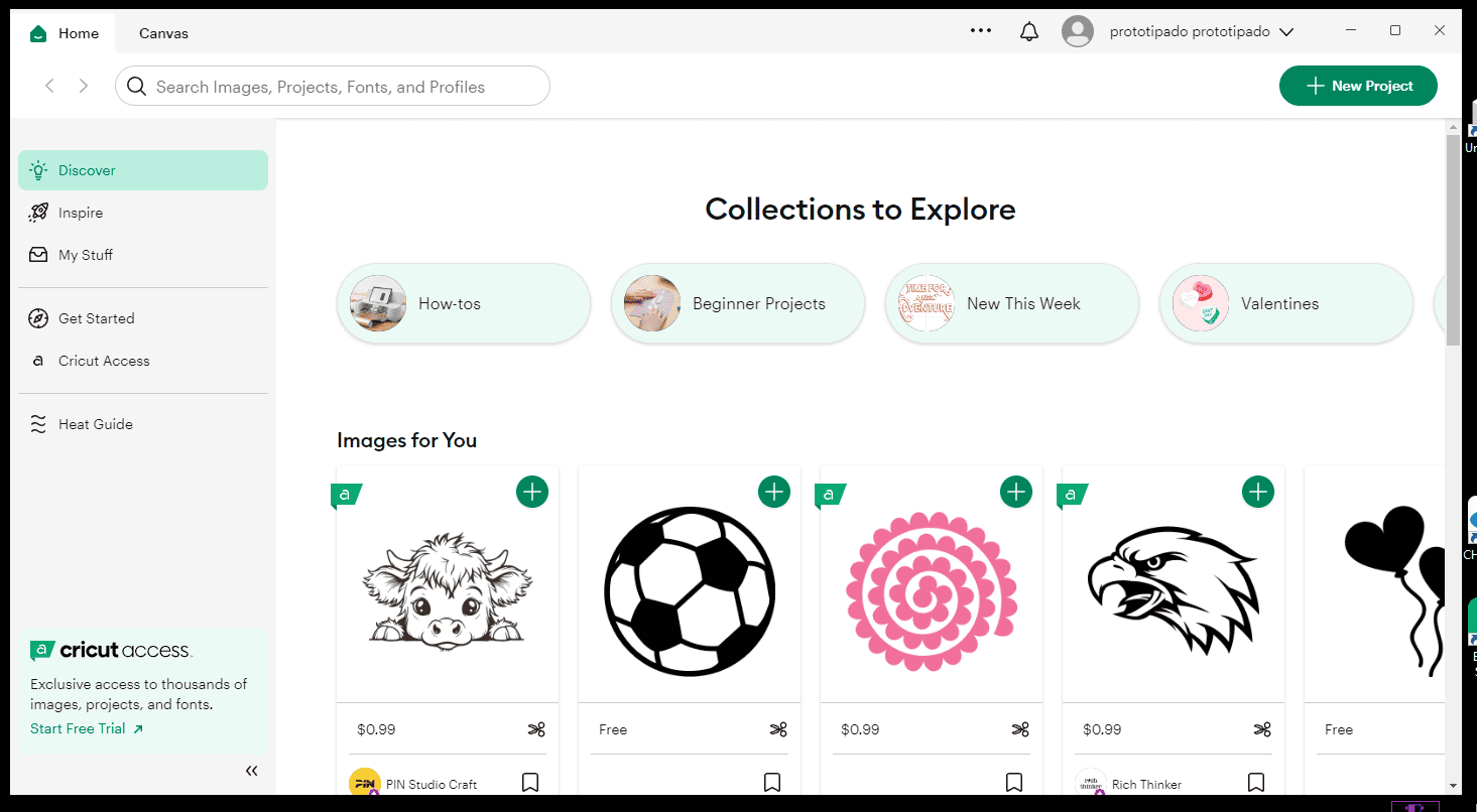
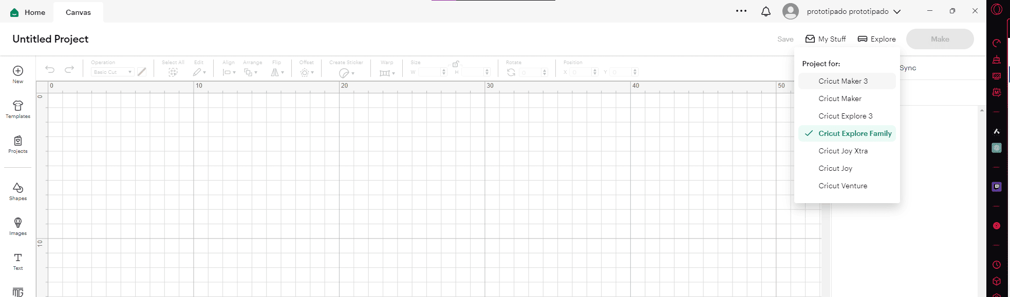
For this project, I set out to cut the FabLab logo using the Cricut Maker 3. I had previously created the logo as a vector in Inkscape, ensuring it met the file requirements for vinyl cutting. When I opened Cricut Design Space, I logged into my account, selected "New Project," and confirmed the machine was properly set up and connected.
|
TOOLS TO USE
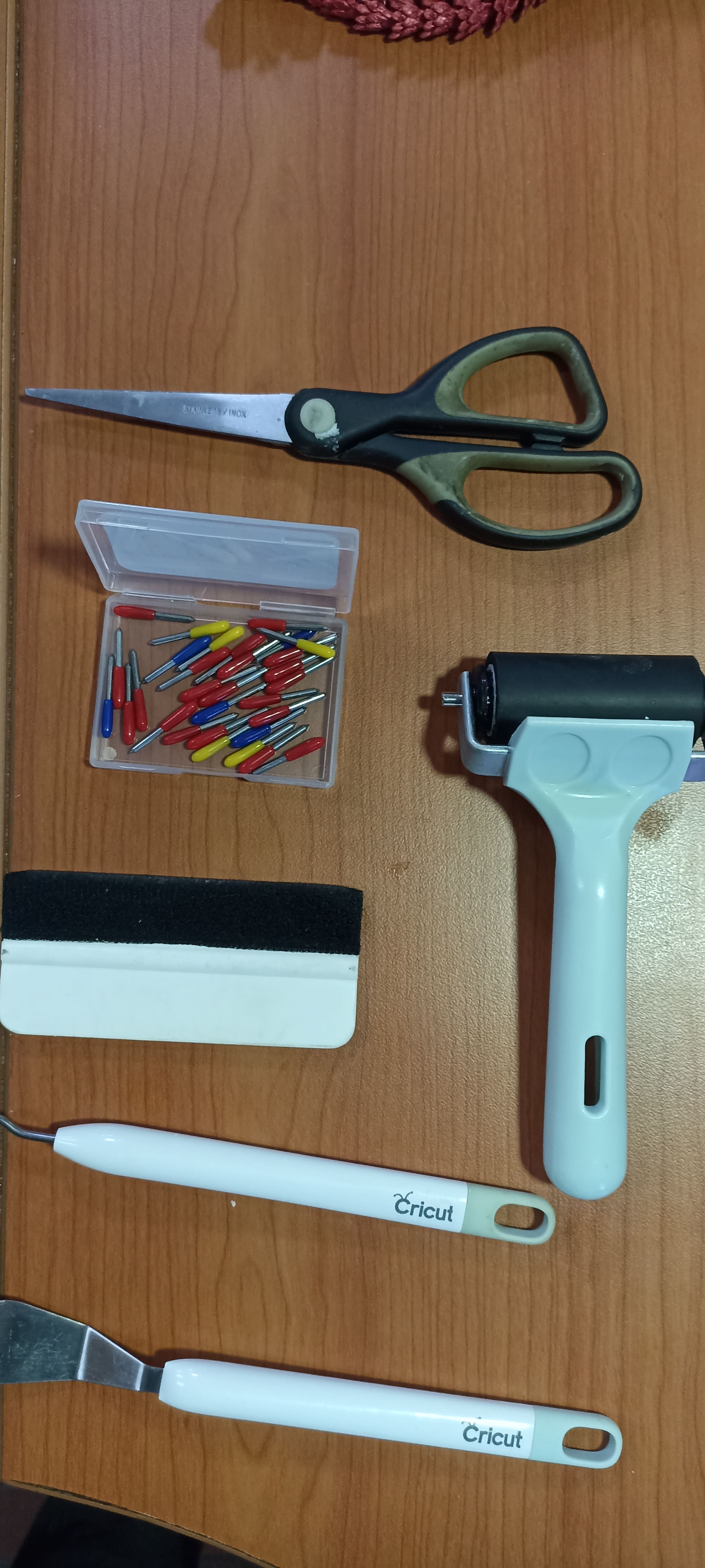
|
In the software, I reviewed the workspace and made sure the framework and settings matched my design requirements.
|
CRICUT SOFTWARE OVERVIEW
|
|
FRAMEWORK IN PROGRAM
|
Importing and Configuring the Design
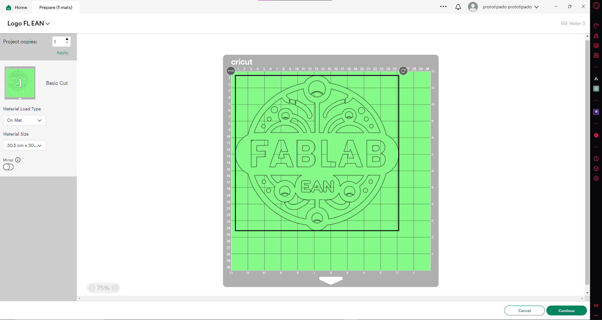
I imported the FabLab logo into the program and adjusted the size to fit the vinyl sheet I was going to use. I made sure to select the right cutting mat and material type in the software.
|
LOGO CONFIGURATION IN SOFTWARE
|
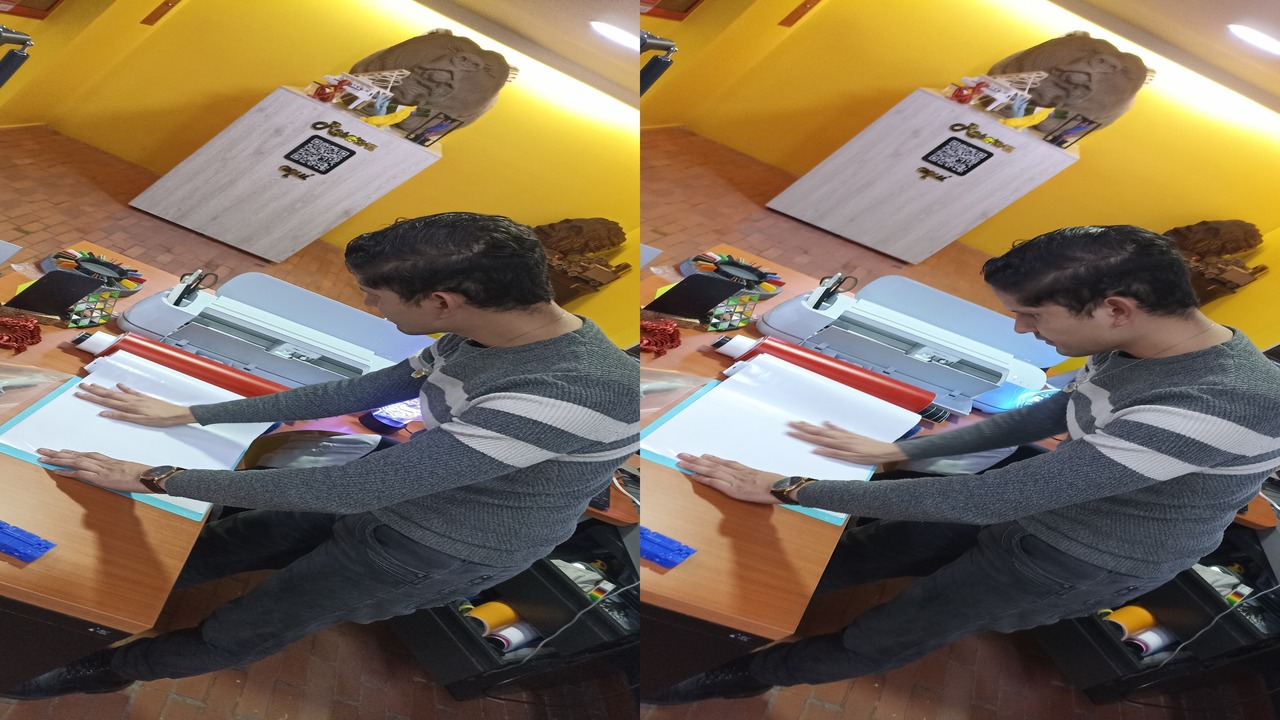
Once the design was ready, I moved on to the physical setup of the material and machine. Before cutting, I prepared the vinyl by carefully placing it on the cutting mat.
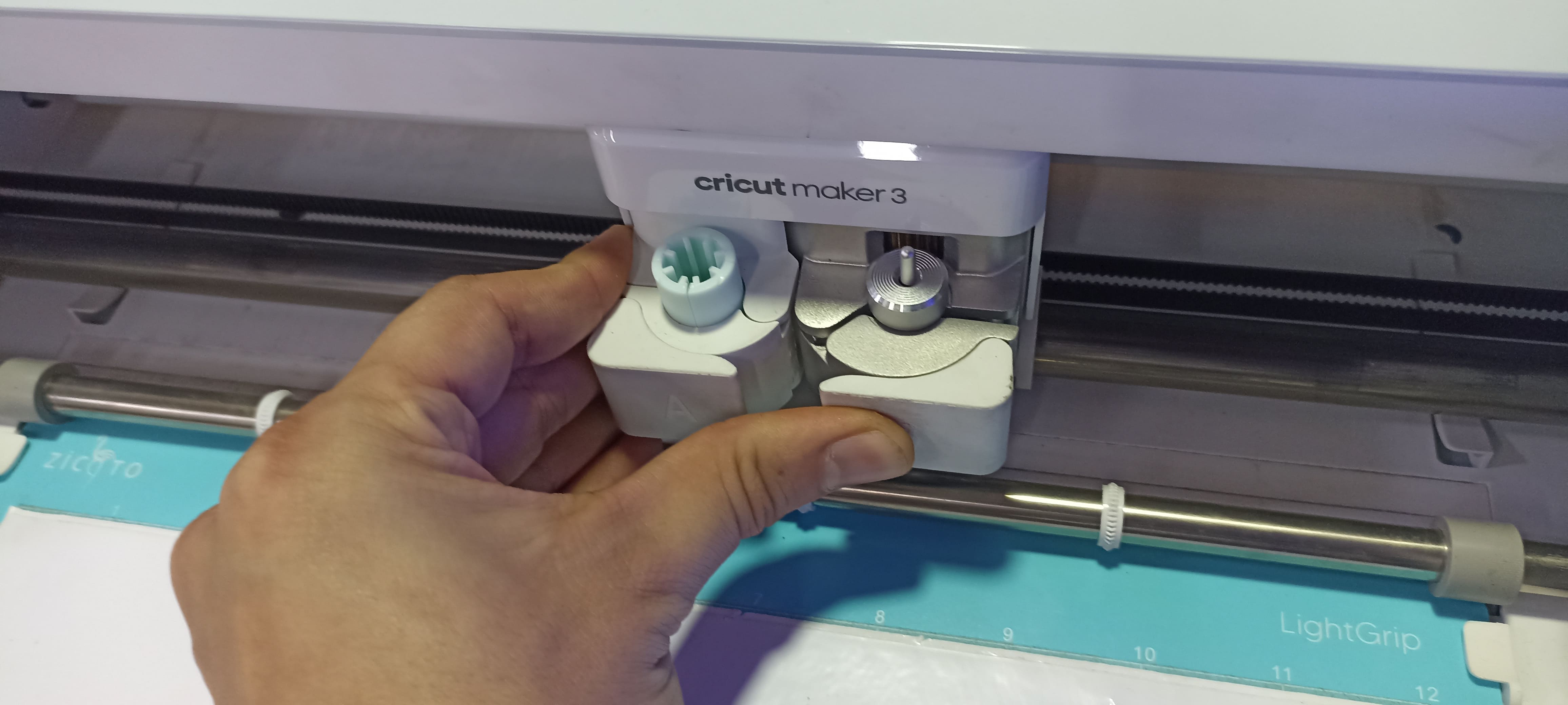
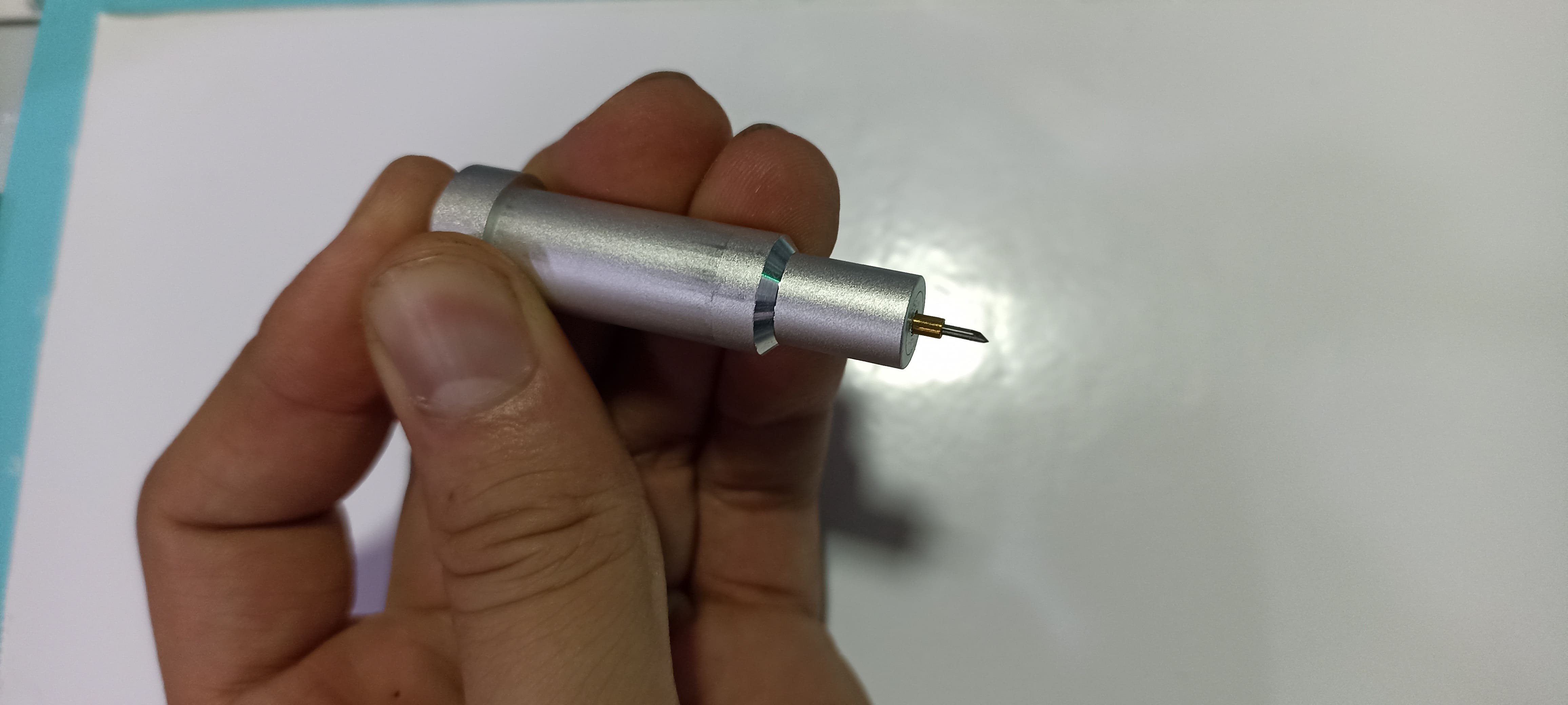
To ensure a clean cut, I dismantled the blade holder, checked for any residue or wear from previous cuts, and cleaned it thoroughly.
|
DISMOUNTING AND CHECKING THE BLADE
|
|
CLEANING THE BLADE
|
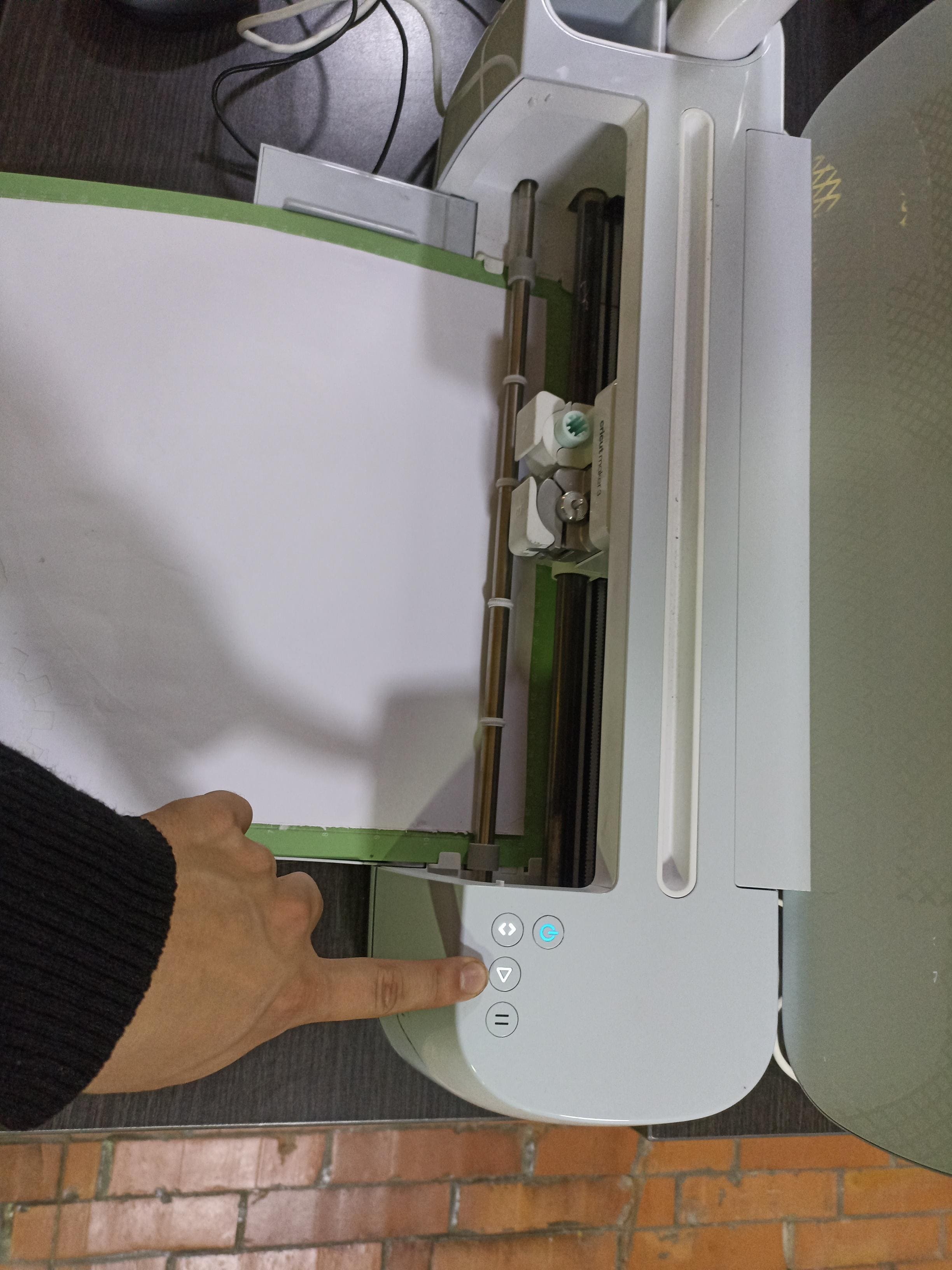
Material Setup and Cutting
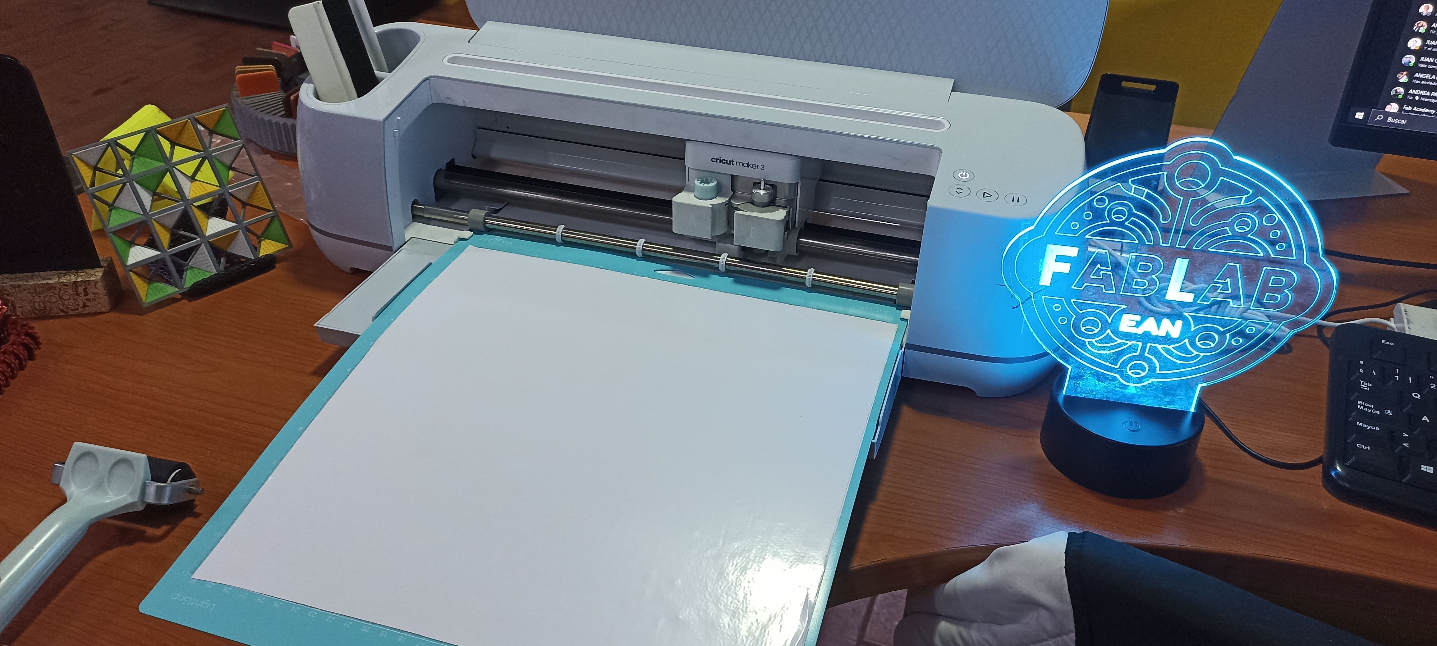
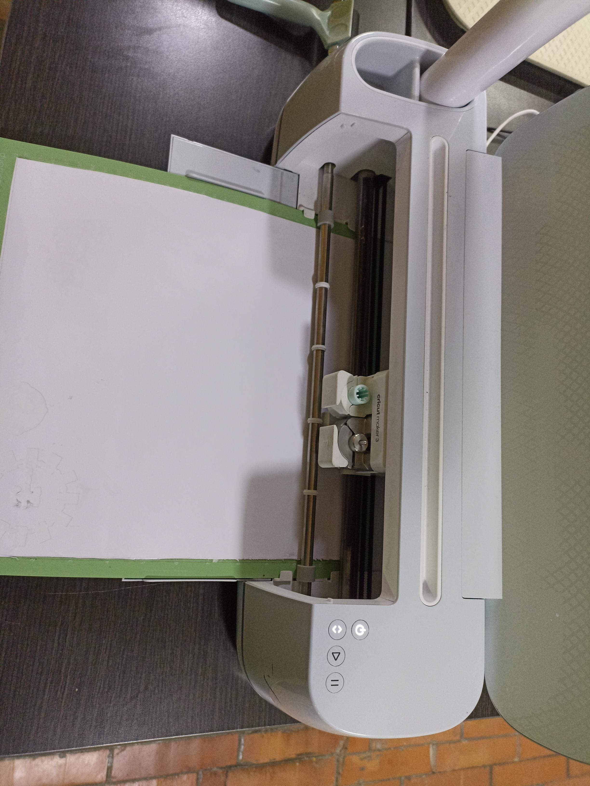
Once the blade was in place and the vinyl was correctly positioned, I inserted the cutting mat into the machine. In the software, I selected the material type, adjusted the cutting force for optimal precision, and sent the command to the machine.
|
MACHINE SETUP
|
|
LOADING THE MATERIAL
|
|
STARTING THE CUT
|
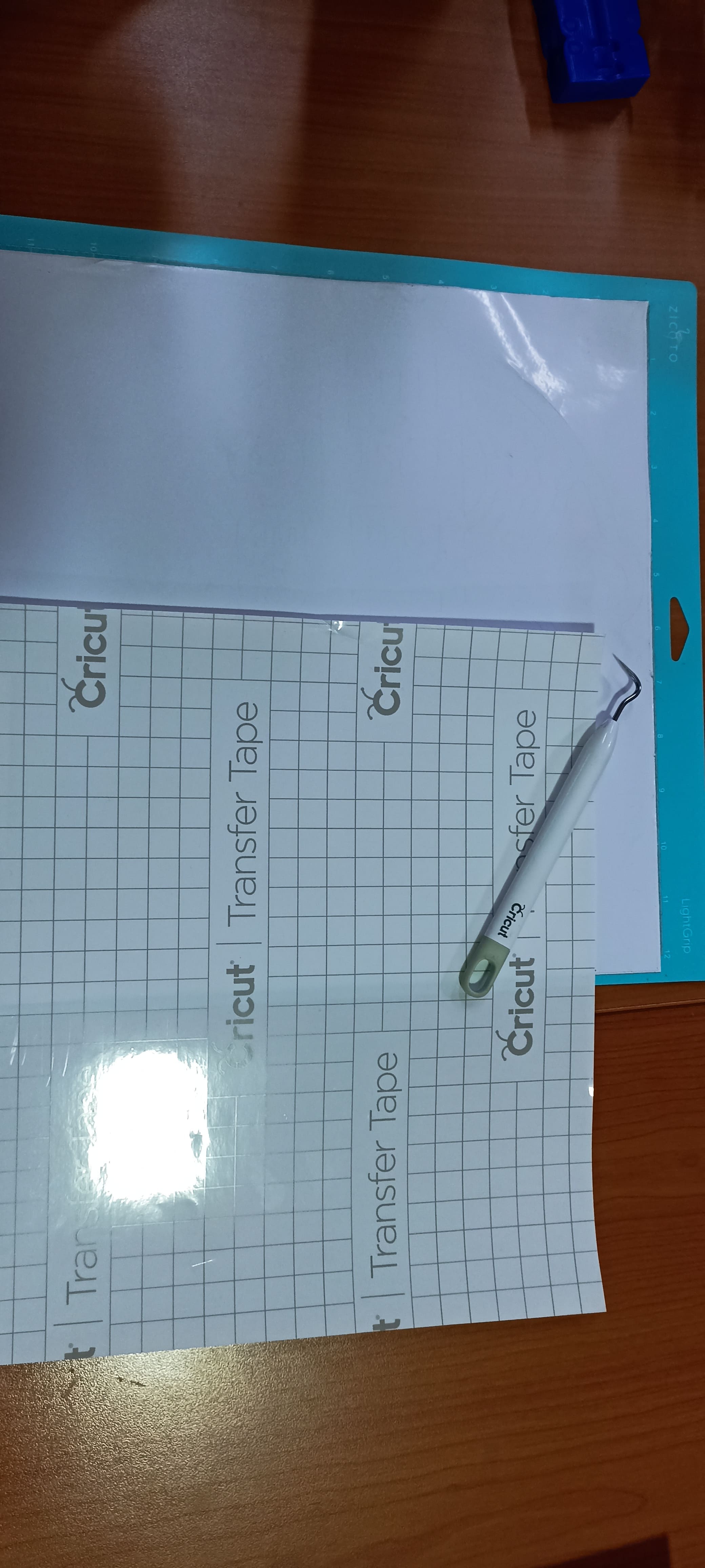
Post-Cut Processing
After the machine finished cutting, I prepared for the transfer process. This involved carefully removing the unnecessary vinyl, applying transfer paper, and preparing the design for application on the wall.
|
TRANSFER PREPARATION
|
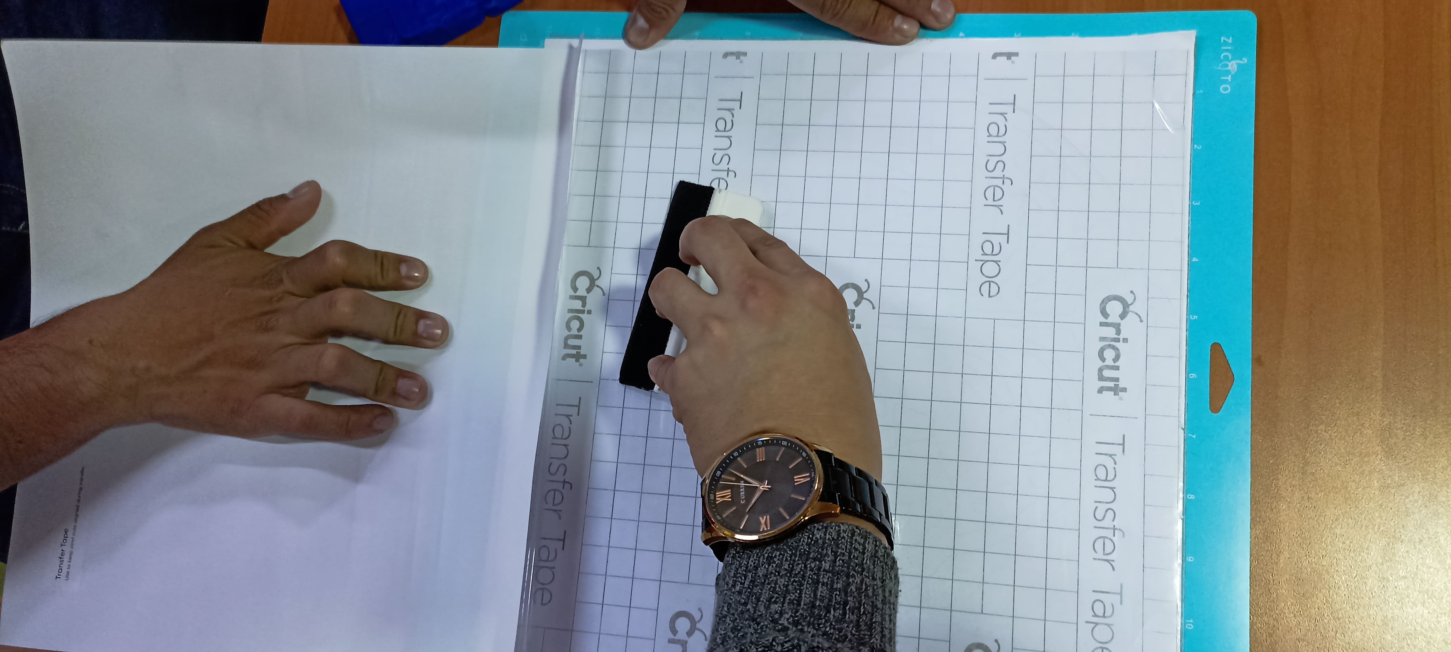
|
APPLYING TRANSFER AND WEEDING VINYL
|
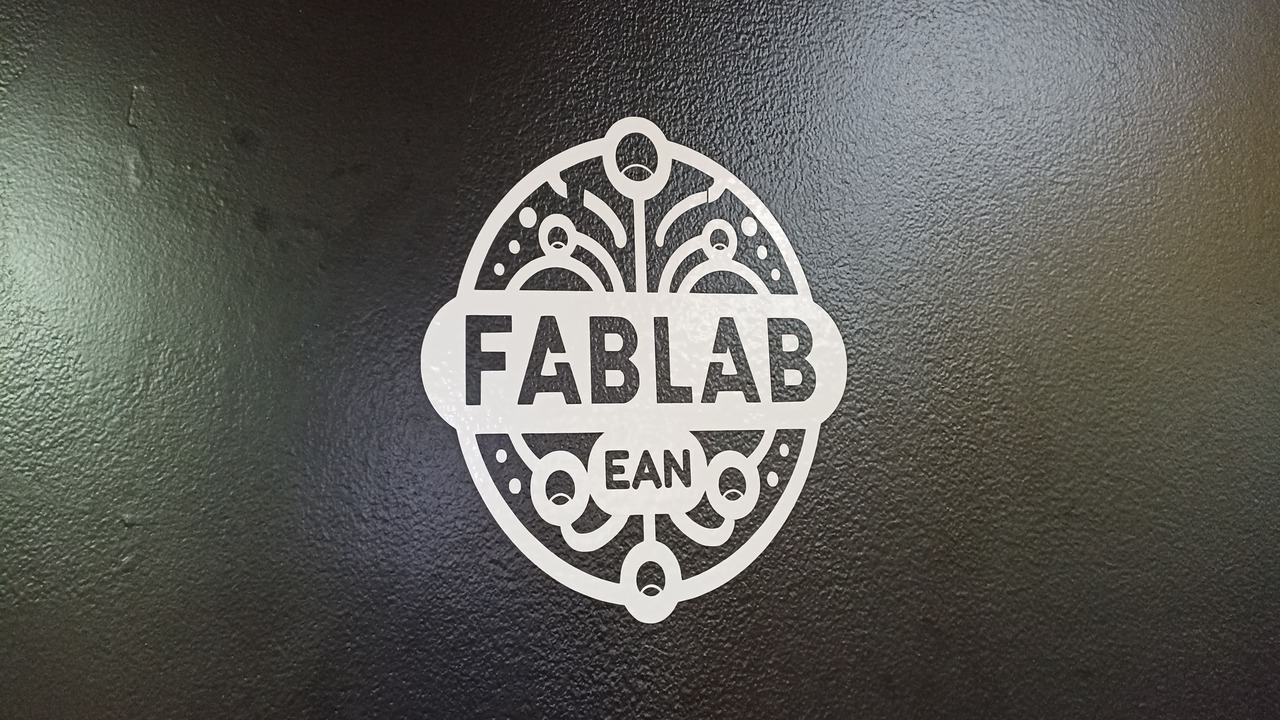
The final result was a beautiful, clean white vinyl logo of the FabLab EAN applied to a striking black wall, giving it a professional and polished look.
This process allowed me to explore not only the technical aspects of vinyl cutting but also the importance of careful preparation and attention to detail. From selecting the correct material and checking the blade to setting up the design and executing the transfer, every step was essential to achieving a high-quality final product.
Personal conclusions from this week
Week 3 was a very important learning experience, as I detailed the importance of safety regulations and the precautions to take when handling these types of machines. This was further reinforced by experience: no one is exempt from accidents, but following the proper steps and paying attention to the details can prevent them. Personally, I didn’t have any problems during this assignment, as laser cutting is one of the techniques I am most skilled in. To carry out the work in the best possible way, I always calibrated and checked the machine's condition before starting, which helped me avoid mistakes in this area, though not in the design phase. Sometimes, due to oversights or not noting certain measurements, I made mistakes that later caused my pieces not to fit. However, I solved this by taking notes and making reminders while working, which helped me avoid these issues. The vinyl cutting process was similar. I know my strength is not in design, which is still my weakest area, but in manufacturing, I was able to highlight my skills. What I could improve in this is by preparing more and strengthening my design skills to create truly amazing things.
Downloads & Resources
LightBurn Files (Laser Cutting)
- 🔗 Parametric Kit – LightBurn File
- 🔗 Power Test – LightBurn File
- 🔗 Kerf Test – LightBurn File
- 🔗 Power Engraving Test – LightBurn File
Vector Exports (SVG & DXF)
- 🔗 Parametric Kit – SVG | DXF
- 🔗 Power Test – SVG | DXF
- 🔗 Kerf Test – SVG | DXF
- 🔗 Power Engraving Test – SVG | DXF