Assignments
Group Assignment:
- Probe an input device(s)'s analog levels and digital signals.
- Document your work on the group work page and reflect on your individual page what
you learned.
Individual Assignment:
- Measure something: add a sensor to a microcontroller board that you have designed
and read it.
Week 9. Input Devices
Group Reflection
For this group assignment, each member explored different tools and techniques to analyze power consumption and signals from various electronic components. My specific contribution focused on the use of a USB power meter (AVHzY CT-3 model), a precise digital instrument capable of measuring voltage, current, and power over USB connections.
I carried out several practical tests with this tool. First, I verified the functionality of a mobile phone charger, resetting the meter and observing a 5.2V baseline. I then used a USB-C to USB-C connection to analyze power flow in real time. For more targeted measurements, I connected the meter to my Xiao ESP-C3 board to determine idle current draw. After one minute, it had only consumed 2.4 mAh, confirming its low power usage.
To go further, I connected output components such as motors to observe how load and friction affect consumption. Using a chassis I had previously designed, I connected motors directly through the USB pin headers and noted consumption increases from 0.026 A to over 0.2 A under friction. These tests were crucial in visualizing how real-world conditions influence energy demand.
My contribution was not only practical but also informative for the group, as it helped contextualize how power meters can be used to validate USB power protocols (PD/QC/PPS), identify faulty cables or chargers, and analyze component behavior under different loads. I also documented every step with images and detailed explanations to share with my teammates and for future reference.
While the group worked independently in parallel due to time constraints, I made sure to document and communicate my findings clearly. This work strengthened my understanding of energy analysis tools and their value in prototyping, validation, and troubleshooting processes. It also gave me a solid base for evaluating efficiency in embedded systems.
1). Introduction
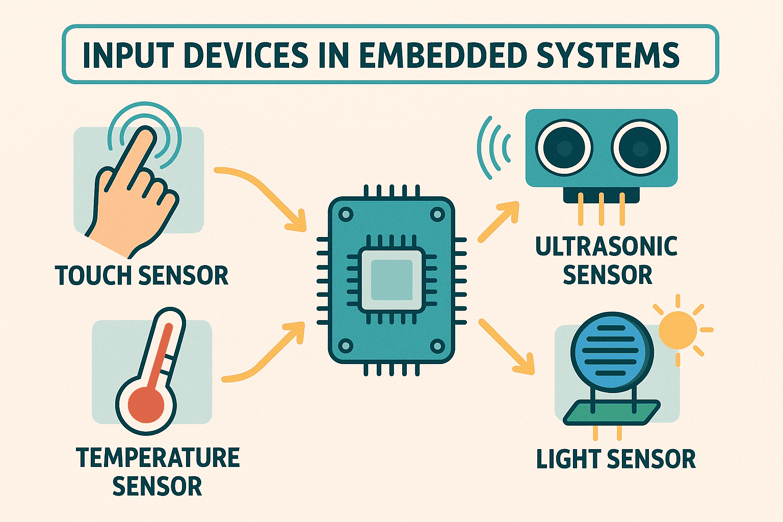
In the context of embedded systems, input devices are essential to enable interaction
between the physical world and digital environments. These devices, also known as input
devices, function to detect environmental variables such as touch, distance, light, or
temperature and translate them into electrical signals that a microcontroller can
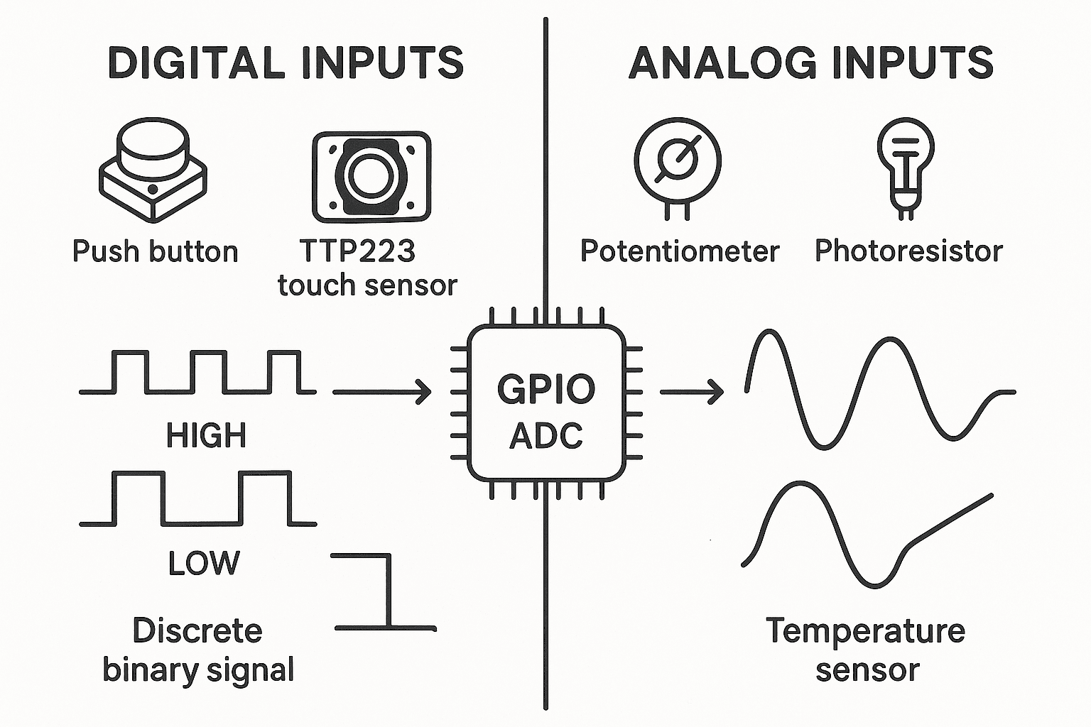
interpret. These signals can be digital, based on binary states (on or off), or analog, when
representing a continuous variation.
The microcontroller used for this activity is an ESP32-S3, a powerful processing unit with
Wi-Fi and Bluetooth connectivity, ideal for real-time interaction and monitoring projects.
The board housing this microcontroller was designed during Week 6 (Electronics Design) of Fab Academy using the Fritzing tool,
which allowed for intuitive circuit schematic creation and PCB layout. Later, in Week 8 (Electronics Production), the machining files were prepared
using Fusion 360 to generate milling paths for PCB production via CNC.
2). TTP223 Touch Sensor
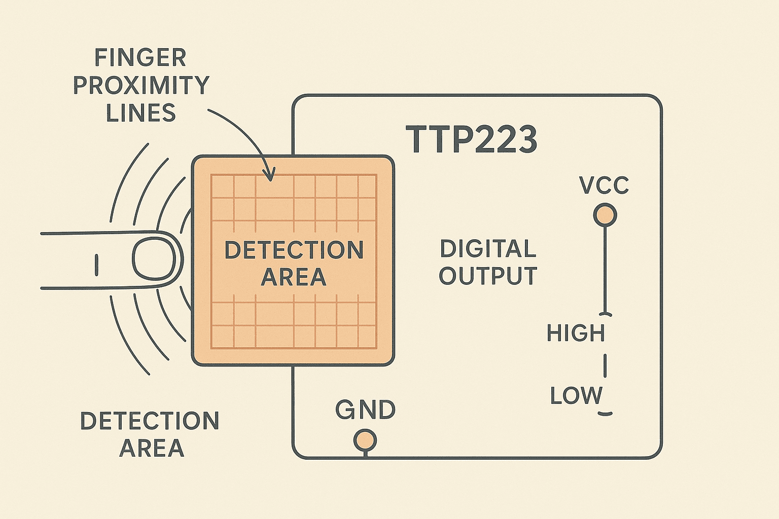
The TTP223 is a capacitive touch panel detector integrated circuit (IC) that emulates the functionality of a physical button using capacitive technology. It is designed to replace traditional switches with a more durable solution without moving parts and greater design flexibility. Through a sensitive area (metal pad or PCB), the TTP223 detects human body proximity or contact reliably.
Operating Principle
The sensor works by measuring changes in the capacitance of the environment near its sensitive
surface. When a finger approaches or touches this area, an electric field variation occurs,
which the IC detects and interprets as a touch signal, generating a digital output easily read
by a microcontroller like the ESP32-S3.
The TTP223 features automatic calibration, with a recalibration period of about 4 seconds when
no touch is detected, ensuring precise detection over time and despite environmental changes.
Signal Types and Operating Modes
By default, the module provides a digital CMOS output (Q pin) that goes HIGH when a touch is detected and stays LOW otherwise. It is highly versatile and configurable via option pads on the PCB:
- Output modes: active HIGH or active LOW (AHLB pin).
- Response modes: momentary (active only while touched) or toggle (changes state with each touch) via TOG pin.
- Power modes: fast or low consumption (LPMB pin).
- Open drain output available on the OPDO pin.
- Sensitivity adjustment: using an external capacitor (0–50 pF) between input and ground.
Technical Specifications
- Operating voltage: 2.0 V to 5.5 V (3.3 V compatible with ESP32-S3).
- Very low standby current, ideal for battery-powered projects.
- Response time: ~60 ms (fast mode), ~220 ms (low power mode at 3 V).
- Module size: 15 mm x 11 mm.
- Startup stabilization time: ~0.5 s (do not touch during this period).
- Max allowed touch duration: 100 seconds (MOTB pin).
3). Simulating the TTP223 with App Designer (MATLAB)
To realistically emulate the touch sensor’s behavior, an application was developed in MATLAB’s
App Designer. It allows users to configure operational modes interactively, similar to using
physical jumpers on the sensor board.
The simulation includes:
- Default signal state: HIGH (1) or LOW (0).
- Activation mode: Momentary (signal changes only while touched) or Toggle (signal toggles on each touch).
Sensor Behavior Simulation
The App Designer simulation replicates both momentary and toggle configurations:
- Momentary: signal pulse occurs during touch only.
- Toggle: signal flips on each touch and stays until the next one.
4). Integration of TTP223 with ESP32-S3 and RGB LED
To visually verify the touch detection, the TTP223 was connected to an ESP32-S3 board and a common anode RGB LED. The sensor’s output pin was linked to the microcontroller, and the RGB LED was configured to turn white upon touch detection by setting all cathodes LOW.
| Component | Pin | ESP32-S3 |
|---|---|---|
| TTP223 | VCC | 3V3 |
| TTP223 | GND | GND |
| TTP223 | I/O | 2 |
| RGB LED | Red cathode | 4 |
| RGB LED | Green cathode | 5 |
| RGB LED | Blue cathode | 6 |
The implemented code detects capacitive touch and controls the RGB LED reliably. A
ledState logic was added to prevent flickering and ensure toggling only on valid
state transitions. This creates a stable, touch-activated interface.
ESP32-S3 – TTP223 Touch Sensor Code
This code detects touch from the TTP223 sensor (pin 2) and toggles a white RGB LED (pins 4, 5, 6).
🧩 Code Breakdown and Explanation
1. #define Section – Pin Configuration
// Define the pin connected to the touch sensor's output
#define TOUCH_PIN 2

// Define the pins connected to the RGB LED cathodes
#define RED_PIN 4
#define GREEN_PIN 5
#define BLUE_PIN 6
This section sets up constant names for each pin used. By using #define, the
code becomes more readable and maintainable. If the hardware design changes, pin numbers can
be updated here without modifying the logic.
2. Variable Declaration – State Control
// Boolean flag to track the current LED state (ON or OFF)
bool ledState = false;
This boolean variable stores the current state of the LED. It prevents the LED from toggling repeatedly during one single touch event, ensuring stable behavior.
3. setup() Function – System Initialization
void setup() {
    Serial.begin(115200);                  // Start serial communication for debugging
    pinMode(RED_PIN, OUTPUT);              // Set Red channel as output
    pinMode(GREEN_PIN, OUTPUT);            // Set Green channel as output
    pinMode(BLUE_PIN, OUTPUT);             // Set Blue channel as output
    pinMode(TOUCH_PIN, INPUT);             // Set the sensor pin as input

    digitalWrite(RED_PIN, LOW);            // Ensure Red LED is OFF at startup
    digitalWrite(GREEN_PIN, LOW);          // Ensure Green LED is OFF
    digitalWrite(BLUE_PIN, LOW);           // Ensure Blue LED is OFF
}
This function runs once when the ESP32-S3 starts. It initializes serial communication for monitoring, sets up the RGB pins as digital outputs, and configures the touch sensor pin as an input. All LED channels are turned off initially to avoid unexpected behavior at power-up.
4. loop() Function – Continuous Execution
void loop() {
    int touchValue = digitalRead(TOUCH_PIN);   // Read current state from TTP223 sensor

    Serial.print("Touch value: ");             // Print label
    Serial.println(touchValue);                // Display raw sensor output (0 or 1)

    if (touchValue == 0) {                     // Check if sensor is being touched
        if (!ledState) {                       // Only activate if LED is currently OFF
            ledState = true;                   // Update LED state
            digitalWrite(RED_PIN, HIGH);       // Turn on Red
            digitalWrite(GREEN_PIN, HIGH);     // Turn on Green
            digitalWrite(BLUE_PIN, HIGH);      // Turn on Blue (all ON = White)
            Serial.println("LED turned ON!");  // Debug message
        }
    } else {
        if (ledState) {                        // If touch is released and LED was ON
            ledState = false;                  // Update LED state
            digitalWrite(RED_PIN, LOW);        // Turn off Red
            digitalWrite(GREEN_PIN, LOW);      // Turn off Green
            digitalWrite(BLUE_PIN, LOW);       // Turn off Blue
            Serial.println("LED turned OFF!"); // Debug message
        }
    }

    delay(100);                                // Small pause to debounce and stabilize readings
}
The loop() function runs indefinitely. It checks the current output of the
touch sensor. If the value is 0, it means the sensor is being touched. Using a
control flag (ledState), the LED only turns on when transitioning from an
untouched to a touched state. When the sensor value returns to 1 (no touch),
the LED turns off. The delay(100) adds a 100 ms buffer to avoid noisy reads or
false triggers.
🔍 Signal Processing and System Behavior
The TTP223 sensor outputs a digital signal either HIGH (1)
or LOW (0) based on the presence of a human finger near its surface. When
there is no touch, the output remains HIGH; when a touch is detected, it drops to LOW. The
microcontroller constantly monitors this output through digitalRead(TOUCH_PIN).
The core logic of the code checks the sensor's output and, depending on the value, either
turns the RGB LED ON or OFF. However, to avoid rapid toggling or flickering (which may occur
due to quick or noisy signal changes), a control variable called ledState is
used. This ensures that the LED changes state only when a valid transition occurs — from
"not touched" to "touched" or vice versa.
📘 Step-by-Step Signal Flow Explanation
- User touches the TTP223 sensor: The sensor detects the change in capacitance and sets its output pin to LOW (0V).
- ESP32-S3 reads this signal: Using
digitalRead(TOUCH_PIN), the microcontroller identifies that a touch occurred. - LED logic is triggered: If the system was OFF, the code updates
ledState = trueand powers all RGB channels to emit white light. - When touch is released: The sensor sets its output pin back to HIGH. If
the LED was ON, the logic sets
ledState = falseand turns off the RGB channels.
🎯 Why Use a State Variable?
Without ledState, the LED would respond to every read cycle in the loop. Since
the loop runs hundreds of times per second, a slight variation or noise could cause
unintended flickering. The state variable ensures that the LED only toggles once per touch,
making the system stable and responsive.
🧠 Educational Insight
This system is an excellent example of digital signal processing in embedded systems. Even though the sensor only provides two logic levels, the use of software logic allows us to transform a basic input into a stable and interactive output. Such approaches are common in modern human-machine interfaces, including touch lamps, interactive displays, and smart appliances.
4). Programming & Behavior
For this assignment, I programmed an ESP32-S3 board with a custom PCB to play a melody using a passive buzzer, while simultaneously displaying the lyrics on a 16x2 I2C LCD screen. The chosen song was “La nave del olvido” by José José — a well-known romantic ballad. The system synchronizes audio (tones) with visual output (lyrics) line by line.
🎶 System Behavior
- LCD (I2C) displays synchronized lyrics using
textopan(). - Passive buzzer plays notes using
nota()andnota_sf(). - Functions like
Espera1()andMeMoriria_2()organize song parts.
🧩 Programming and Upload Steps
Below is the complete process I followed to upload the code and verify the correct behavior of both the buzzer and the LCD screen.
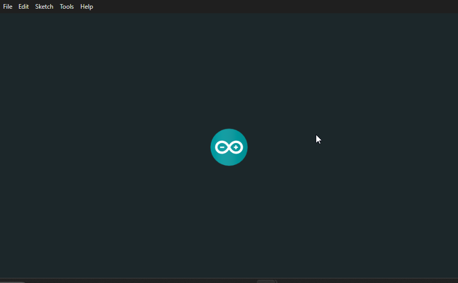
Step 1 – Open Arduino IDE
I launched the Arduino IDE and made sure it was ready to work with ESP32-S3 boards.
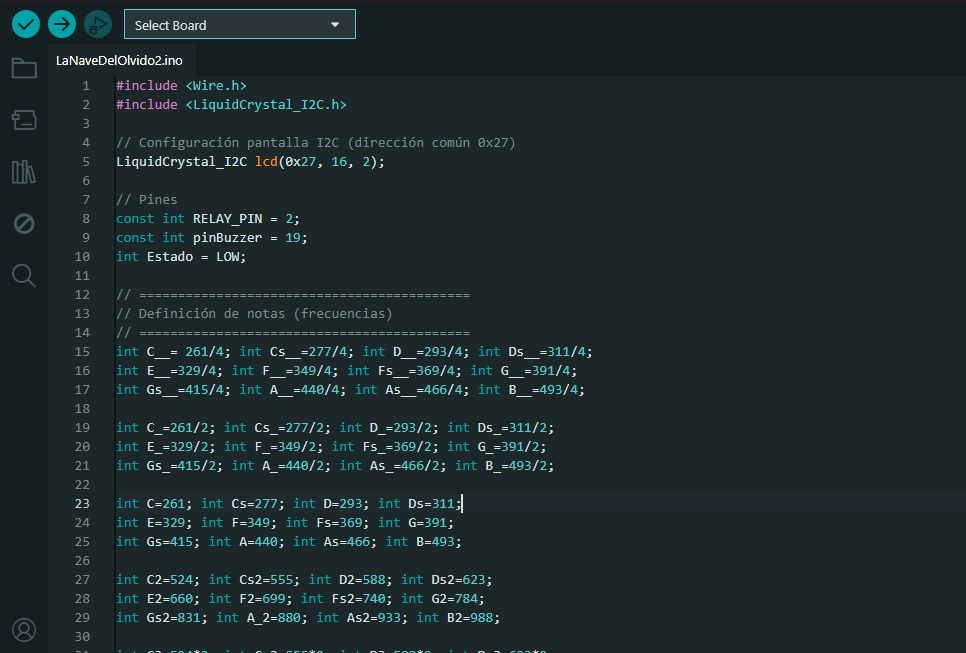
Step 2 – Paste the Song Code
I pasted the full program that includes functions for each verse and note. I made sure to
include LiquidCrystal_I2C and define the correct pins for LCD and buzzer.
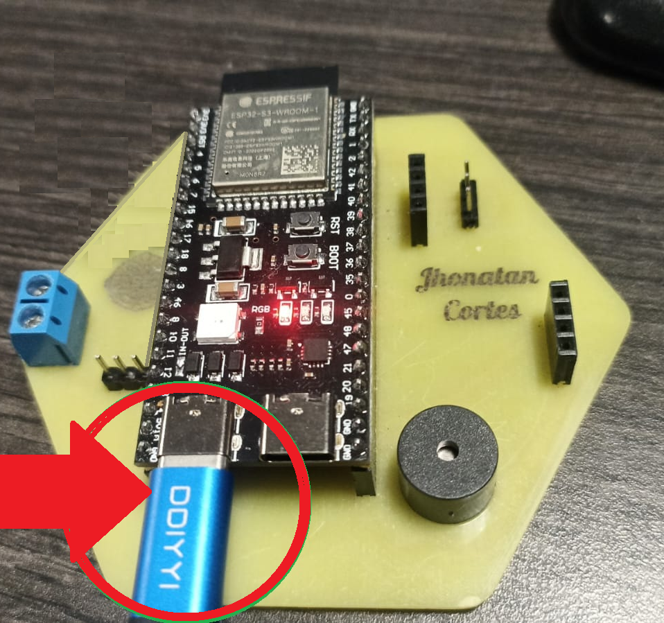
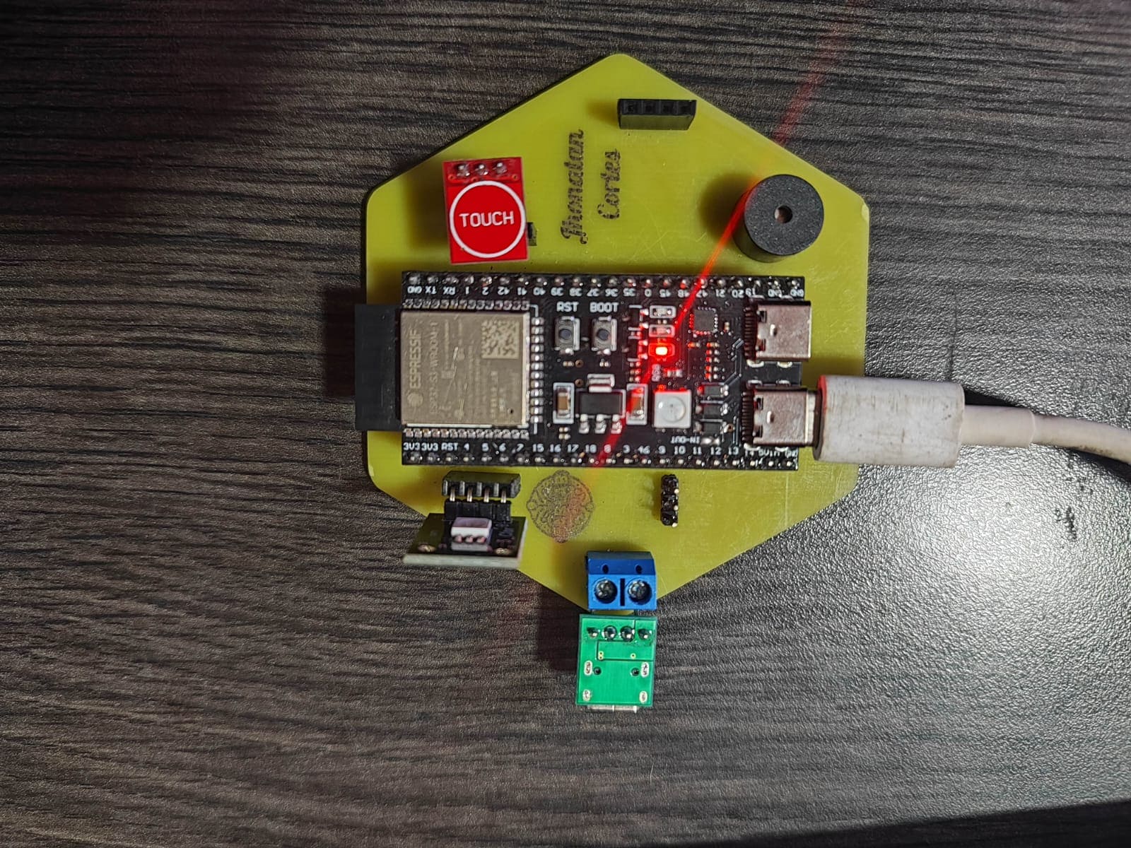
Step 3 – Connect the Board
I connected the ESP32-S3 to my PC via USB-C. The board powered up and was recognized by the IDE.
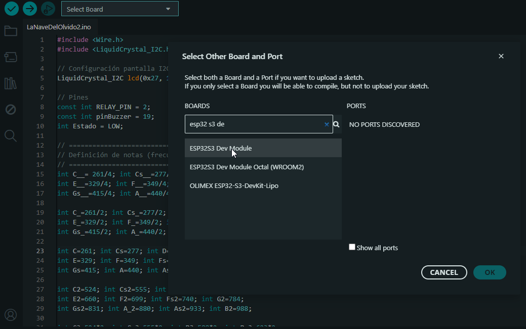
Step 4 – Select the Board
In Tools > Board, I selected ESP32S3 Dev Module, which is compatible with
my PCB design.
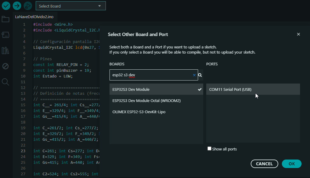
Step 5 – Select the COM Port
I selected the COM port automatically assigned to the ESP32-S3. This ensures that the code is uploaded to the correct hardware.
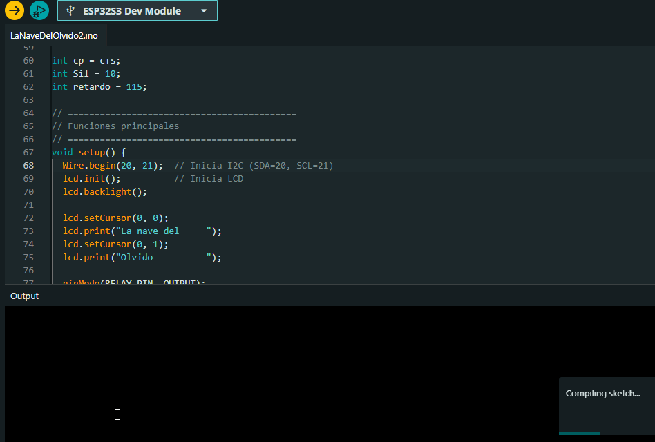
Step 6 – Upload the Code
Once everything was set, I clicked the upload button. The IDE compiled and uploaded the code successfully. I monitored the serial console to confirm proper execution.
🧾 Summary
This project helped me reinforce concepts like pin assignment, timing control, and modular programming. The result was a fun and interactive musical system that plays a classic Latin song with visual lyrics — all running from my custom PCB.
This experiment successfully demonstrates how a capacitive touch sensor can be integrated into an embedded system to provide real-time digital input with visual feedback. By using both simulation and physical measurements, the sensor’s behavior was confirmed to match theoretical expectations. This highlights its reliability and usefulness for interactive embedded applications.
6). Validating TTP223 Behavior with Oscilloscope
A digital oscilloscope was used to monitor the sensor’s output in real time. The probe was connected to the TTP223’s output pin, and GND was connected to the circuit’s ground. Observations showed:
- Normal (untouched): signal remains LOW (~0 V).
- On touch: signal quickly jumps to HIGH (~3.3 V).
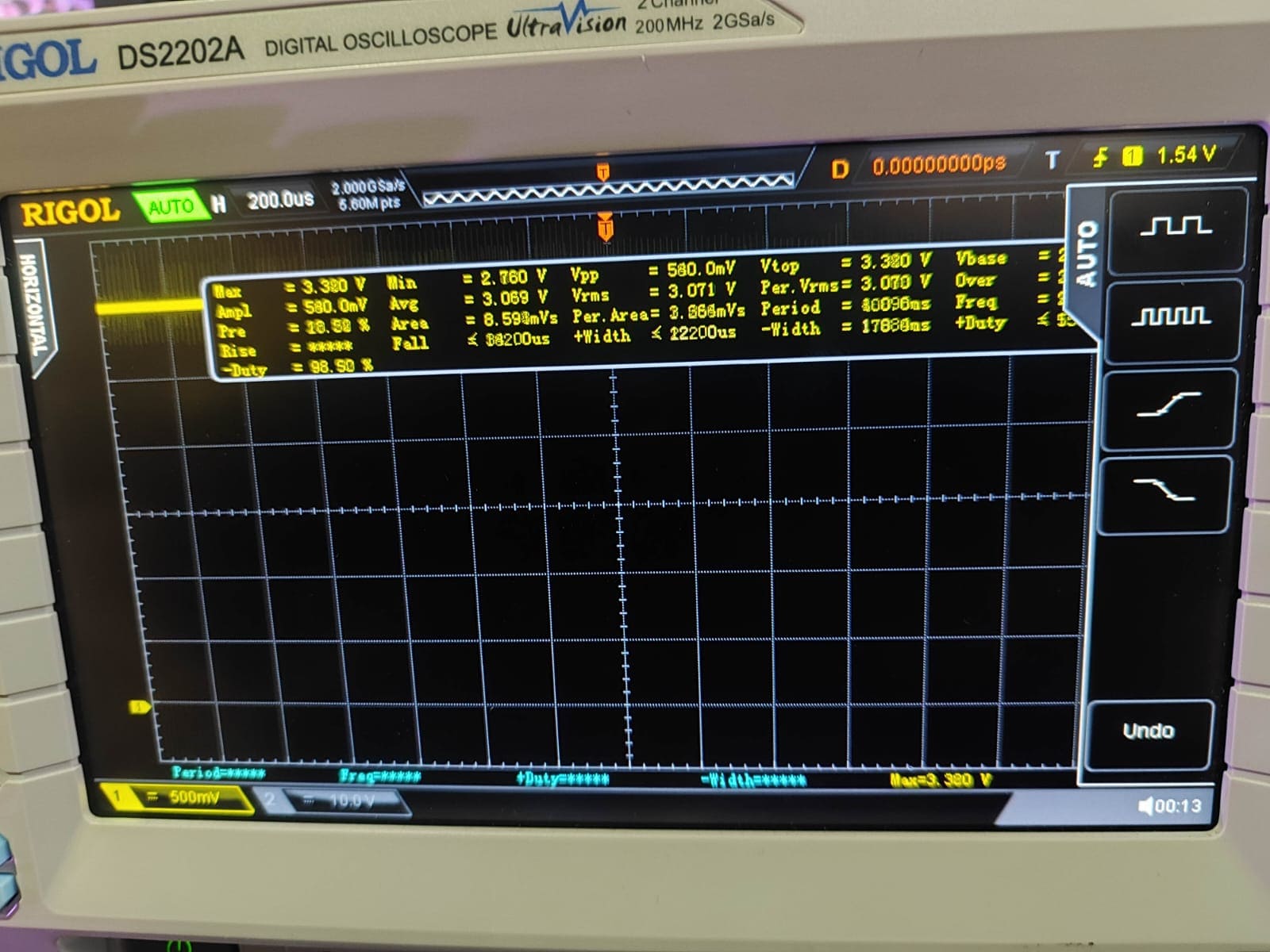
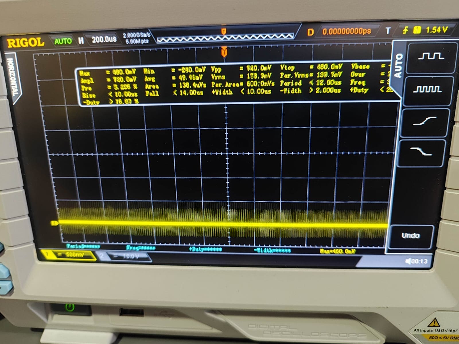
This matches the default active-high configuration and confirms theoretical and simulated behavior.
Conclusions
This week gave me a deeper understanding of how input devices work, especially in terms of signal behavior and their role in embedded systems. I learned to distinguish between analog and digital signals not only theoretically, but through practical testing with an oscilloscope and direct sensor integration.
One of the most enriching parts was combining simulation with physical implementation. Using MATLAB’s App Designer, I was able to simulate the touch sensor’s behavior under different configurations. Later, I integrated the TTP223 with my custom ESP32-S3 board and an RGB LED to test the real response of the system.
Although I didn’t face wiring issues, I did run into a logic error during programming. Because the RGB LED is common anode, I was initially sending HIGH signals to the output pins expecting the LED to turn on, but instead, the colors turned off. Once I understood the reversed logic, I adjusted the code to set the pins LOW when turning the LED on, which resolved the issue.
I also encountered a bug where the LED flickered due to repeated state changes. I solved
this by adding a state control variable ledState to ensure the LED only toggled
when the touch value changed, making the behavior more stable and reliable.
Overall, this assignment strengthened my confidence in integrating and programming input devices. I also improved my debugging process and reinforced the importance of understanding how both hardware and software interact in real time.