Assignments
Group Assignment:
- Measure the power consumption of an output device.
- Document your work on the group work page and reflect on your individual page what
you learned.
Individual Assignment:
- Add an output device to a microcontroller board you’ve designed and program it to
do something.
Week 10. Output Devices
🔋 Group Reflection – Power Measurement Learnings
For this week’s group assignment on power measurements, I took the initiative to explore the use of a specialized tool: the AVHzY CT-3 USB Power Meter. While others in the group focused on simpler setups or theoretical discussions, I documented a full series of practical tests using this advanced device.
This digital meter is capable of reading voltage, current, and power consumption through USB ports, and it supports protocols like PD, QC, and PPS. I began by measuring a standard mobile charger, then used a USB-C to USB-C setup to test different components in real conditions. I reset the readings to zero and started capturing real-time data such as voltage, current draw, and accumulated energy usage.
I measured the idle power consumption of my Xiao ESP-C3 board
through its USB-C port and then tested a series
of motors mounted on a small chassis I had previously designed. I connected the
motors directly to the power meter and tested
them both idle and under friction. I observed clear variations in current draw: from
as low as 0.02A to peaks of
0.2A depending on the load and movement.
I also prepared a breadboard-friendly USB adapter for future tests, making it easier to integrate sensors and small components into this kind of analysis. These tests allowed the group to better understand how different elements behave in terms of power usage and helped validate why certain cables, power sources, or batteries may fail under load.
My contribution directly provided the group with real measurement data, visual evidence, and practical interpretations. Thanks to this, we could draw clear conclusions about energy consumption, the impact of mechanical resistance, and even how to identify good or faulty USB cables.
This activity helped the group go beyond theory and experience real-world conditions. Personally, it also allowed me to improve my testing methodology and gave me valuable insights for future power-sensitive designs.
1️⃣ Introduction & Concept Inspiration
This week's individual assignment was inspired by a video I saw on Instagram, posted in a local maker group from my country. The video showed a buzzer playing a melody, and it immediately sparked my interest. I thought, “What if I took this a step further by adding an LCD screen to display the lyrics alongside the melody?”
I decided to choose a song that is deeply recognized by Spanish-speaking audiences: "El Triste" by José José — one of the most iconic romantic ballads of Latin American music. This choice allowed me to work not only with the buzzer to recreate the melody, but also integrate an LCD I2C screen to show the lyrics line by line.
During my research, I found several code examples for Arduino that played melodies with buzzers, and some examples also used LCDs — but not with I2C, which is the type of display I’m using. That’s why I had to modify and adapt the available code to be compatible with my own I2C LCD and, most importantly, with the custom PCB I created during Week 8 – Electronics Production.
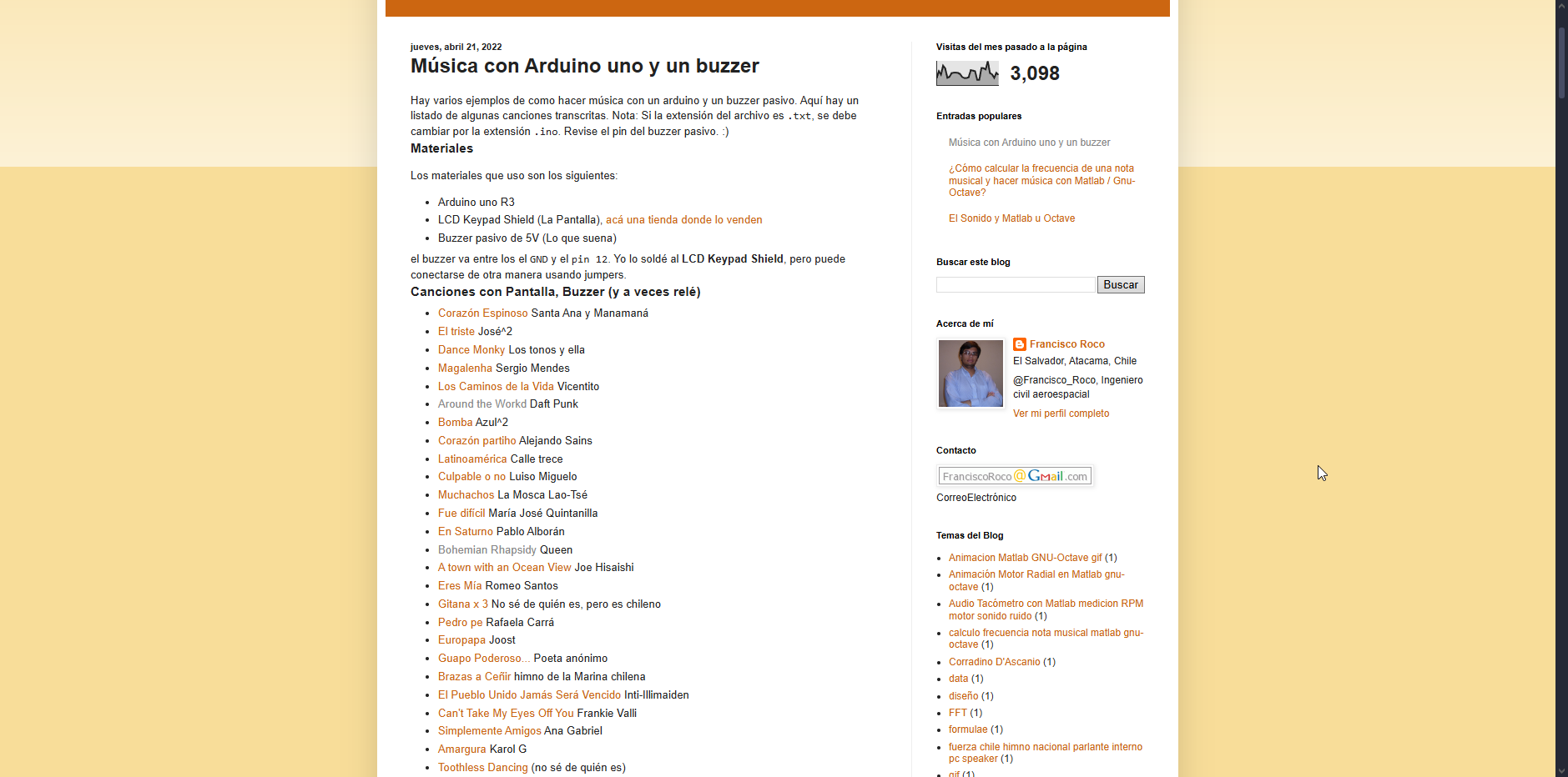
The original page that helped me understand how to generate music with Arduino and buzzers (including sheet-style code) was this blog: Música con Arduino y un Buzzer – RocoBlog .
2️⃣ System Design Overview
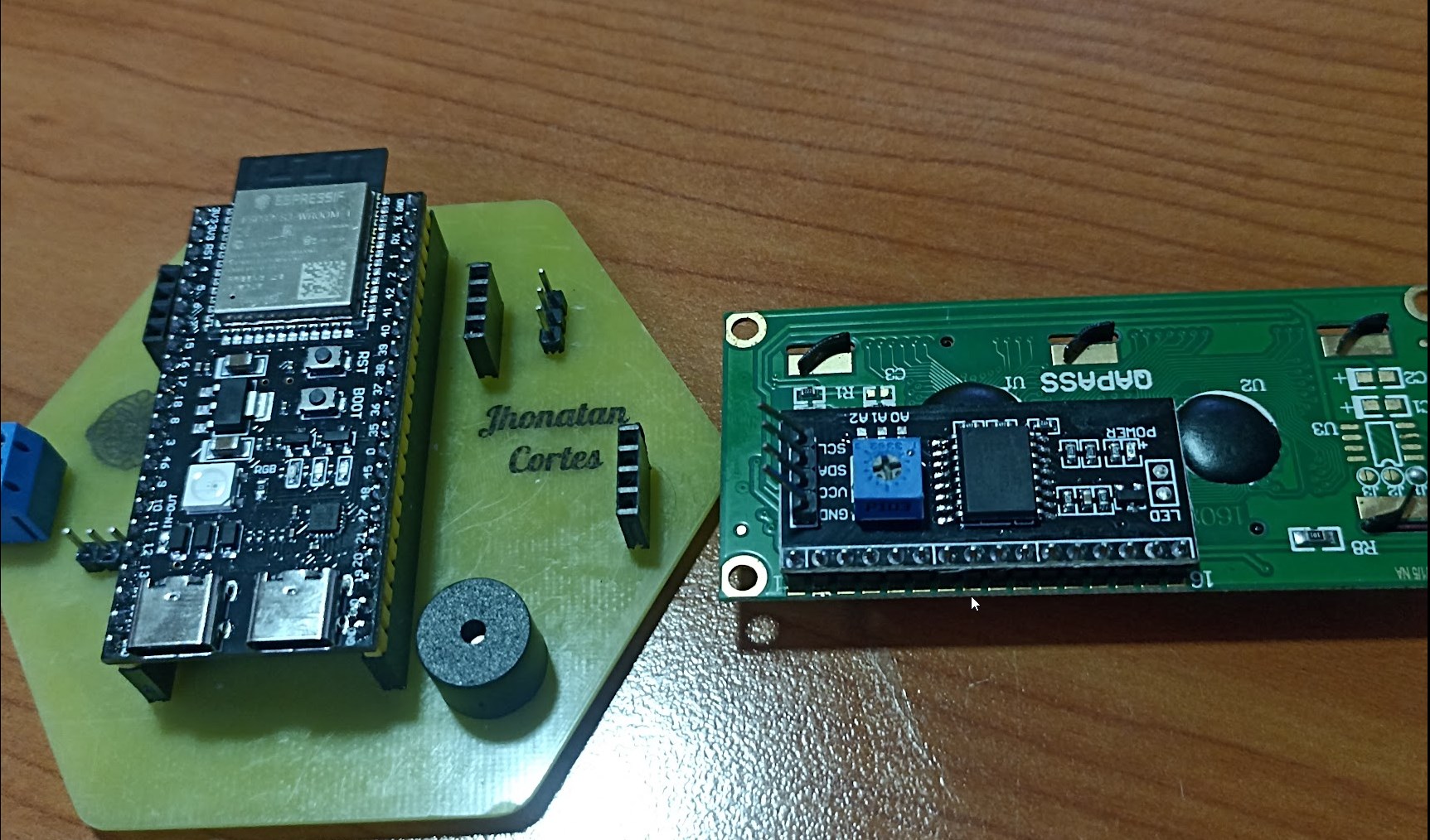
For this assignment, I used the custom expansion board I designed during Week 8 (Electronics Production). This board was created specifically to extend the capabilities of the ESP32-S3 module, allowing for simplified integration of both input and output devices.
As part of its design, the board includes a dedicated I2C header for a 16x2 LCD display, simplifying the connection with just four pins (VCC, GND, SDA, SCL). Additionally, it includes a pre-soldered passive buzzer connected to a GPIO pin, allowing for simple tone-based audio output without requiring any extra wiring or breadboards.
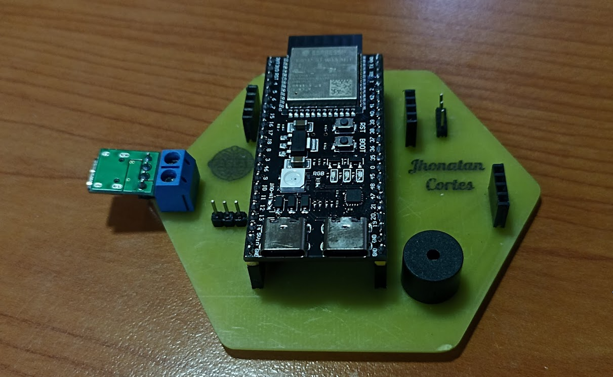
Custom ESP32-S3 Expansion Board with pre-soldered buzzer and I2C LCD port
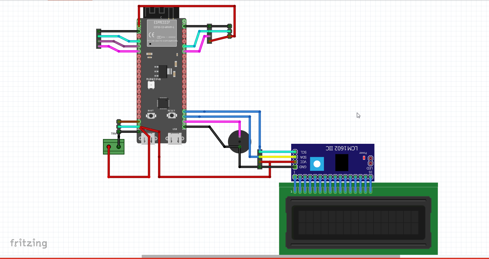
Board schematic showing LCD I2C connection and buzzer pin
This integrated design allows for rapid testing and deployment of audiovisual experiences. The onboard buzzer is controlled through digital signals for sound output, while the LCD is used to display real-time lyrics synced with the melody — a fun and interactive way to explore combined output devices.
3️⃣ Wiring & Pin Configuration
The wiring for this setup was kept simple, thanks to the use of an I2C LCD
module and a pre-soldered passive buzzer on my custom
ESP32-S3 expansion board. The LCD uses the common 0x27 I2C address and
requires only two GPIOs for communication (SDA and SCL), while the buzzer is connected
to a single digital pin.
It's important to note that the LCD module requires 5V to operate correctly. Although the ESP32-S3 operates at 3.3V logic levels, most I2C LCD modules have pull-up resistors and logic level protection that allow safe operation at 5V.
| Component | Pin | ESP32-S3 GPIO | Notes |
|---|---|---|---|
| LCD I2C | VCC | 5V | Power Supply (Required) |
| LCD I2C | GND | GND | Common Ground |
| LCD I2C | SDA | GPIO 20 | Serial Data |
| LCD I2C | SCL | GPIO 21 | Serial Clock |
| Buzzer | Signal | GPIO 19 | Audio output |
🎵 ESP32-S3: LCD + Buzzer Setup Code
This code sets up an I2C LCD and buzzer to play a melody while displaying lyrics line by line.
#include <Wire.h>
#include <LiquidCrystal_I2C.h>

// LCD configuration with I2C address (usually 0x27), 16 columns and 2 rows
LiquidCrystal_I2C lcd(0x27, 16, 2);

// Pin assignments
const int RELAY_PIN = 2;      // Optional relay pin, not actively used in this melody
const int pinBuzzer = 19;     // Buzzer output pin
int Estado = LOW;             // State for relay toggle

// ===========================================================
// NOTE FREQUENCIES (musical tones divided by octaves)
// These are frequency values used to play the melody
// ===========================================================
int C__= 261/4; int Cs__=277/4; int D__=293/4; int Ds__=311/4;
int E__=329/4; int F__=349/4; int Fs__=369/4; int G__=391/4;
int Gs__=415/4; int A__=440/4; int As__=466/4; int B__=493/4;

int C_=261/2; int Cs_=277/2; int D_=293/2; int Ds_=311/2;
int E_=329/2; int F_=349/2; int Fs_=369/2; int G_=391/2;
int Gs_=415/2; int A_=440/2; int As_=466/2; int B_=493/2;

int C=261; int Cs=277; int D=293; int Ds=311;
int E=329; int F=349; int Fs=369; int G=391;
int Gs=415; int A=440; int As=466; int B=493;

int C2=524; int Cs2=555; int D2=588; int Ds2=623;
int E2=660; int F2=699; int Fs2=740; int G2=784;
int Gs2=831; int A_2=880; int As2=933; int B2=988;

int C3=524*2; int Cs3=555*2; int D3=588*2; int Ds3=623*2;
int E3=660*2; int F3=699*2; int Fs3=740*2; int G3=784*2;
int Gs3=831*2; int A_3=880*2; int As3=933*2; int B3=988*2;

int C4=524*4; int Cs4=555*4; int D4=588*4; int Ds4=623*4;
int E4=660*4; int F4=699*4; int Fs4=740*4; int G4=784*4;
int Gs4=831*4; int A_4=880*4; int As4=933*4; int B4=988*4;

// ===========================================================
// RHYTHMIC VALUES (note durations in milliseconds)
// ===========================================================
int tempo = 90;
int semi = 60000/(tempo * 4 *2);
int corch = 2*semi;
int negra = corch*2;
int np = corch*3;
int blanca = negra*2;
int redonda = blanca*2;
int rep = 3*negra;
int bnp = 3*negra+3*corch;

int b = blanca;
int r = 2*b;
int n = negra;
int c = corch;
int s = semi;
int f = s/2;
int sf = f/2;

int cp = c+s;
int Sil = 10;       // Silence / pause between notes
int retardo = 115;  // Delay used in tone separation

// ===========================================================
// SETUP – Initialize LCD and pins
// ===========================================================
void setup() {
  Wire.begin(20, 21);        // I2C connection (SDA = GPIO 20, SCL = GPIO 21)
  lcd.init();                // Start LCD
  lcd.backlight();           // Enable LCD backlight

  // Display intro message
  lcd.setCursor(0, 0);
  lcd.print("La nave del     ");
  lcd.setCursor(0, 1);
  lcd.print("Olvido          ");

  pinMode(RELAY_PIN, OUTPUT);  // Relay pin configured as output
  delay(1900);
}

// ===========================================================
// LOOP – Calls melody sequence functions in order
// ===========================================================
void loop() {
  Espera1();
  Espera2();
  MeMoriria_1();

  Espera1();
  Espera2();
  MeMoriria_2();
  delay(1900);
}

// ===========================================================
// SONG SECTIONS – Combined melody and LCD text
// ===========================================================
void Espera1(){
  textopan("Espera          ","un poco...      ");
  nota(A, c);
  nota(B, c);
  nota(C2, c);
  nota_sf(B, c);
  nota(A, c);

  textopan("       O O     ","        _'      ");
  nota(E_, c);
  nota(A_, c);

  textopan("un poquito      ","                ");
  nota(A, c);
  nota(C2, c);
  nota_sf(F2, b+c);
  nota(C2, c);

  textopan("un poquito    / ","             mas");
  nota_sf(C2, c);
  nota(B, n);

  textopan("       _ _      ","        _ '     ");
  nota(G__, c);
  nota(B__, c);
  nota(D_, c);
  nota(G__, np);

  textopan("para llevarte   ","                ");
  nota(B, c);
  nota(C2, c);
  nota(D2, c);
  nota_sf(C2, c);
  nota(B, 3*c);

  textopan("mi felicidad    ","                ");
  nota(A, c);
  nota(G, c);
  nota_sf(E2, 5*c);

  nota(B, c);
  nota_sf(B, c);
  nota(A, n);

  textopan("       o o     ","      ' _      ");
  nota(A__, c);
  nota(C_, c);
  nota(E_, c);
  nota(F__, c);
  nota(F__, c);
  nota(F__, c);
}

void Espera2(){
  textopan("Espera          ","un poco...      ");
  nota(A, c);
  nota(B, c);
  nota(C2, c);
  nota_sf(B, c);
  nota(A, 3*c);

  textopan("un poquito      ","                ");
  nota(G, c);
  nota(F, c);
  nota_sf(D2, 5*c);
  nota(A, c);

  textopan("un poquito    / ","             mas");
  nota(A, c);
  nota(Gs, n);

  textopan("       _ _      ","      ' _ '     ");
  nota(E_, c);
  nota(Gs_, c);
  nota(B_, c);
  nota(E_, c);
  nota(E_, c);
  nota(E_, c);
}

void MeMoriria_1(){
  textopan("        /       ","Me MORIRIA      ");
  nota(B, c);
  nota(C2, c);
  nota(D2, c);
  nota(C2, c);
  nota(B, 3*c);

  textopan("                ","si te vas...    ");
  nota(B, c);
  nota(D2, c);
  nota(E2, 3*c);
}

void MeMoriria_2(){
  textopan("        /       ","Me MORIRIA      ");
  nota(B, c);
  nota(C2, c);
  nota(D2, c);
  nota(E2, n);
  nota(D2, n);

  textopan("                ","si te vas...    ");
  nota(C2, c);
  nota(B, c);

  textopan("       _ _     ","      ' _ '    ");
  nota(A, 6*c);
}

// ===========================================================
// SUPPORT FUNCTIONS – Notes, Display, Relay
// ===========================================================

// Plays a tone and adds silence after
void nota(int nota, int duracion){
  tone(pinBuzzer, nota, duracion);
  delay(duracion);
  noTone(pinBuzzer);
  delay(duracion);
}

// Special note fade-in style (progressive frequency modulation)
void nota_sf(int N, int d){
  int ttt = sf/2;
  nota(N * 0.84089641525, ttt);
  nota(N * 0.89089871814, ttt);
  nota(N * 0.94387431268, ttt);
  nota(N, d - 3*ttt);
}

// Displays two lines of lyrics on LCD
void textopan(String S1, String S2){
  lcd.setCursor(0, 0);
  lcd.print(S1);
  lcd.setCursor(0, 1);
  lcd.print(S2);
}

// Optional: toggles relay on/off (not used actively here)
void suenaRele(){
  Estado = !Estado;
  digitalWrite(RELAY_PIN, Estado);
}
4️⃣ Programming and Upload Steps
To program my ESP32-S3 custom PCB, I used the Arduino IDE, which allowed me to write, compile, upload, and test the code step by step. The goal was to generate a musical sequence on a passive buzzer, synchronized with lyrics displayed on a 16x2 LCD screen. Below is the complete flow from software configuration to functional verification on hardware.
Step 1 – Open Arduino IDE
I opened the Arduino IDE on my computer, which is the main software used for writing and uploading code to microcontrollers. Before proceeding, I confirmed that the esp32 board package was installed through the Boards Manager.
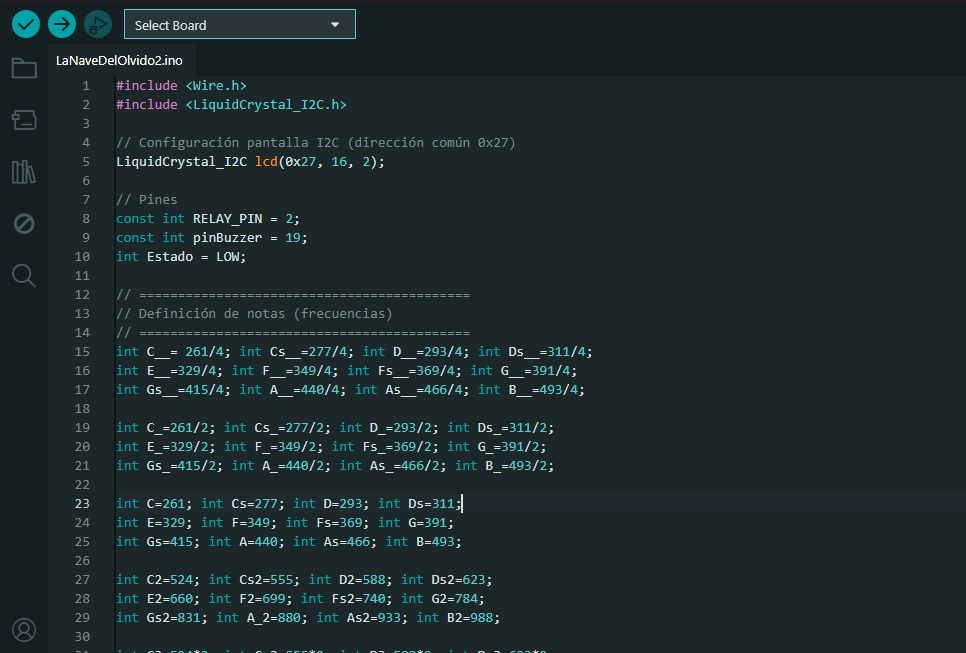
Step 2 – Paste and Verify the Code
I pasted the complete code, which includes the melody logic, note timing, and LCD text display functions. I reviewed the libraries used (e.g., Wire.h and LiquidCrystal_I2C.h), confirmed pin assignments, and organized each verse of the song into modular functions.
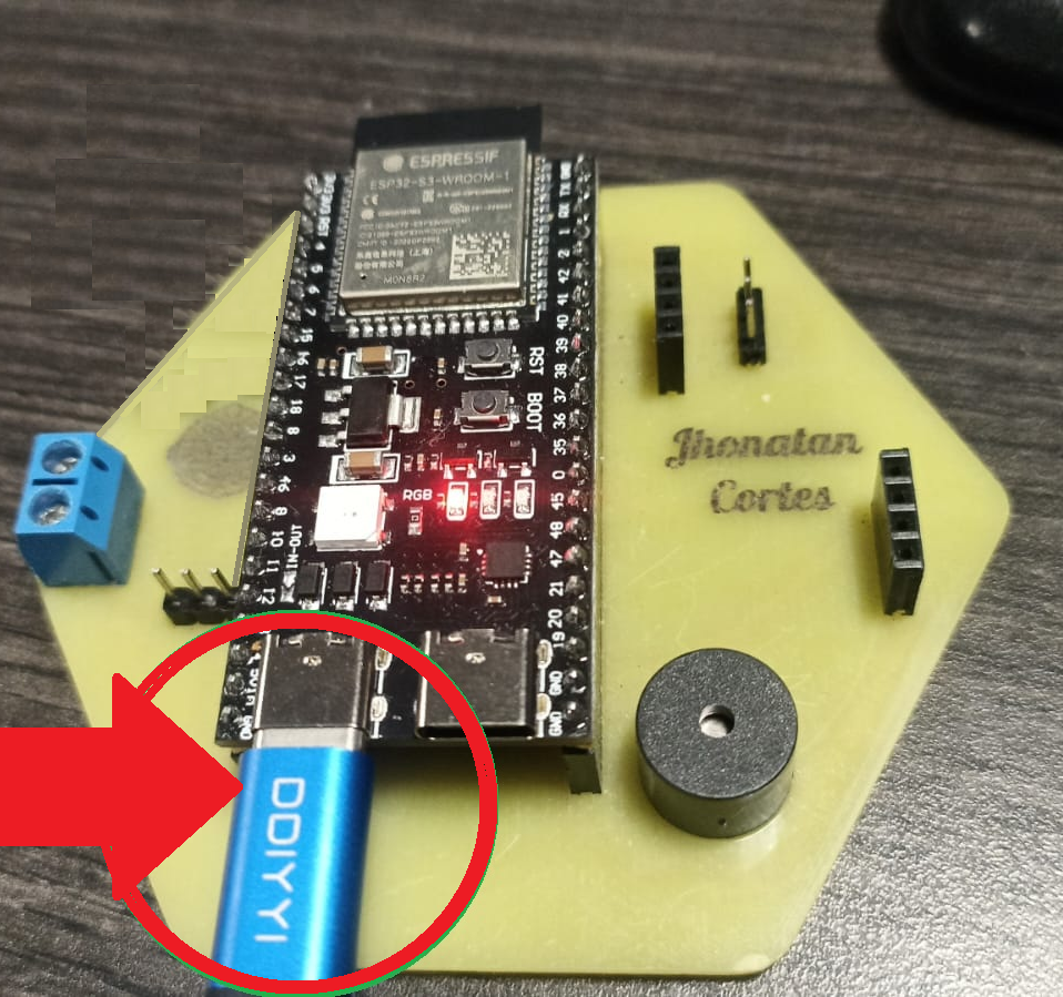
Step 3 – Connect ESP32-S3 Board
Using a USB-C cable, I connected my ESP32-S3 custom board to the computer. The board was recognized automatically by the Arduino IDE, and the USB port was enabled for data and power.
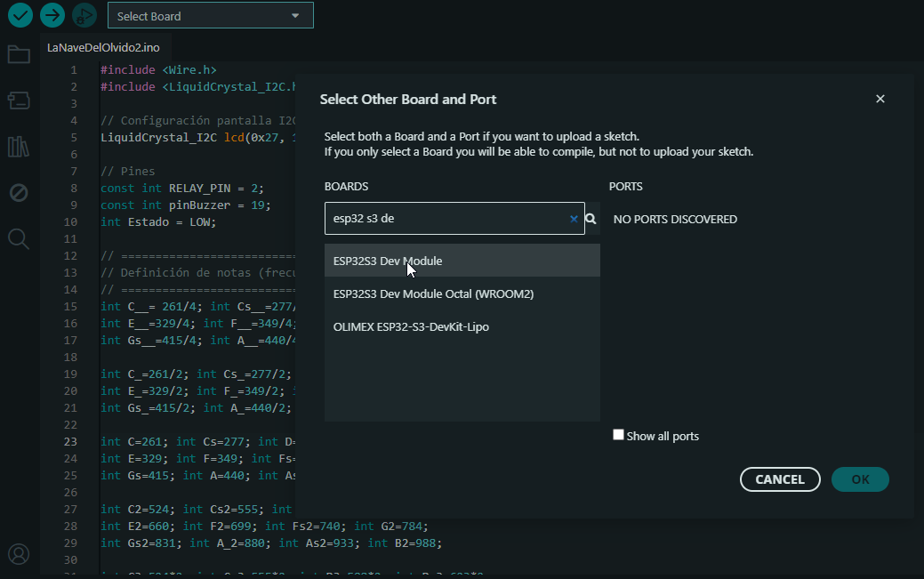
Step 4 – Select the ESP32 Board
In the Tools > Board menu, I selected ESP32S3 Dev Module, which is the correct target for my custom PCB based on ESP32-S3. This step ensures compatibility with the microcontroller’s features and pin definitions.
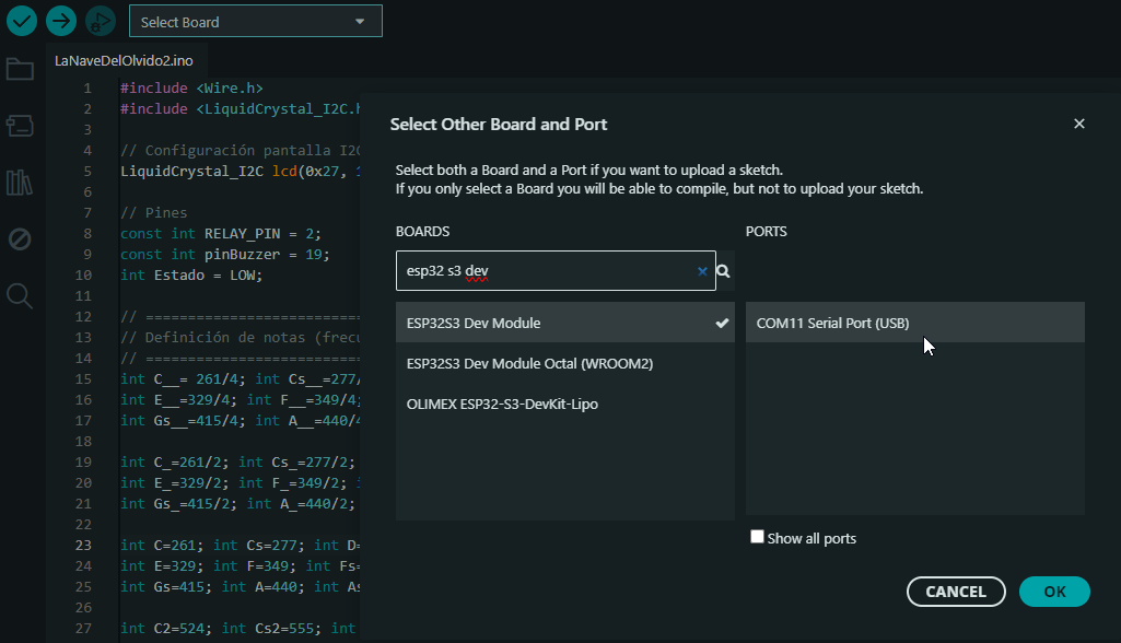
Step 5 – Select the COM Port
I verified the COM port automatically assigned to the board under Tools > Port. This is necessary so the IDE can communicate with the ESP32 and upload the code via USB.
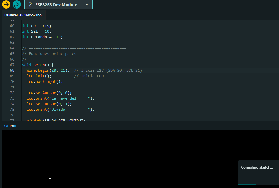
Step 6 – Upload the Code to the Board
I clicked the Upload button (→) to compile and transfer the program to the ESP32-S3. Once uploaded, the code started running automatically. I opened the Serial Monitor at 115200 baud to confirm that the setup was executed correctly.
5️⃣ Results: Operation & Demo
The final result successfully demonstrates the synchronized operation of the buzzer and the LCD display. The board plays the melody "La nave del olvido" using the passive buzzer, while the LCD shows the corresponding lyrics line by line. This project highlights how embedded systems can deliver both auditory and visual outputs in a coordinated manner.
The video below shows the full sequence running on my custom PCB. You can clearly hear the tones being played and watch the lyrics scrolling across the screen, synchronized with each musical segment.
🎵 Video: ESP32-S3 playing “La nave del olvido” with synchronized LCD lyrics
6️⃣ Troubleshooting & Fixes
During the development of this assignment, I didn’t encounter major wiring or logic
issues. However, one important challenge arose when working with the I2C LCD
library. Some versions of the LiquidCrystal_I2C library were not fully
compatible with the ESP32-S3, causing the LCD to not respond or display garbage
characters.
To fix this, I tested several different versions of the library until I found one that was fully compatible. I installed multiple I2C-related libraries through the Arduino IDE, comparing behavior until the LCD worked correctly with the I2C protocol on my custom PCB.
Once the correct library was found and installed, the display started working flawlessly with the ESP32-S3. I also made sure the I2C address (0x27) matched the screen’s address using an I2C scanner sketch beforehand.
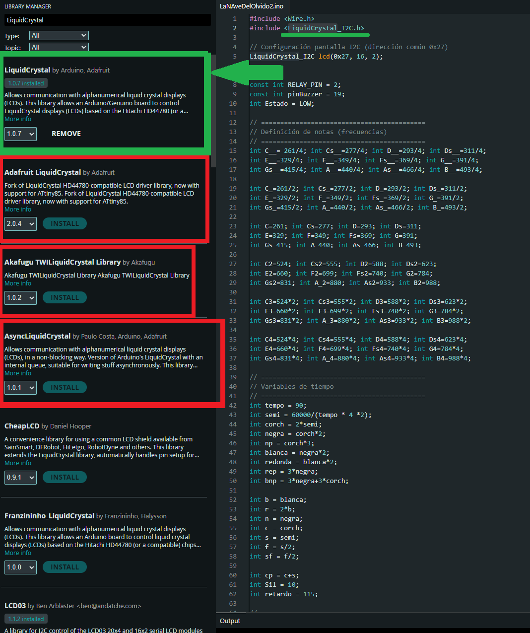
🛠️ Screenshot: I2C and LCD-related libraries tested and installed to ensure compatibility with ESP32-S3
🧠 Reflections & Learnings
This week, I learned to work with different types of output devices, each with their own behavior and requirements. Some devices required the correct libraries to function properly, especially when using the ESP32-S3 microcontroller. This taught me that hardware selection must go hand in hand with compatible software support.
My understanding of output devices has improved significantly. I now understand how to manage multiple components simultaneously and how to control the execution timing of each one to avoid conflicts. This is essential when building more complete and complex projects that combine audio, visuals, and interaction.
If I were to make a new version of this project, I would choose a different output device—perhaps an OLED display. The LCD with I2C is functional, but its limitations in displaying icons, emojis, or expressive text made me want more. A graphical screen would open up more creative possibilities.