Assignments
Assignment:
- Design and document the system integration for your final project.
Week 15 – System Integration
This week focused on putting together all the systems developed in previous weeks to form a fully integrated and functional final project. From packaging and wiring to complete system testing, every element was prepared to make the prototype look and behave like a real product.
1. Implemented Methods of Packaging
In order to protect the electronics and ensure a reliable and clean integration, I designed and implemented a complete packaging solution for my final project. The system consists of multiple customized components built with digital fabrication tools:
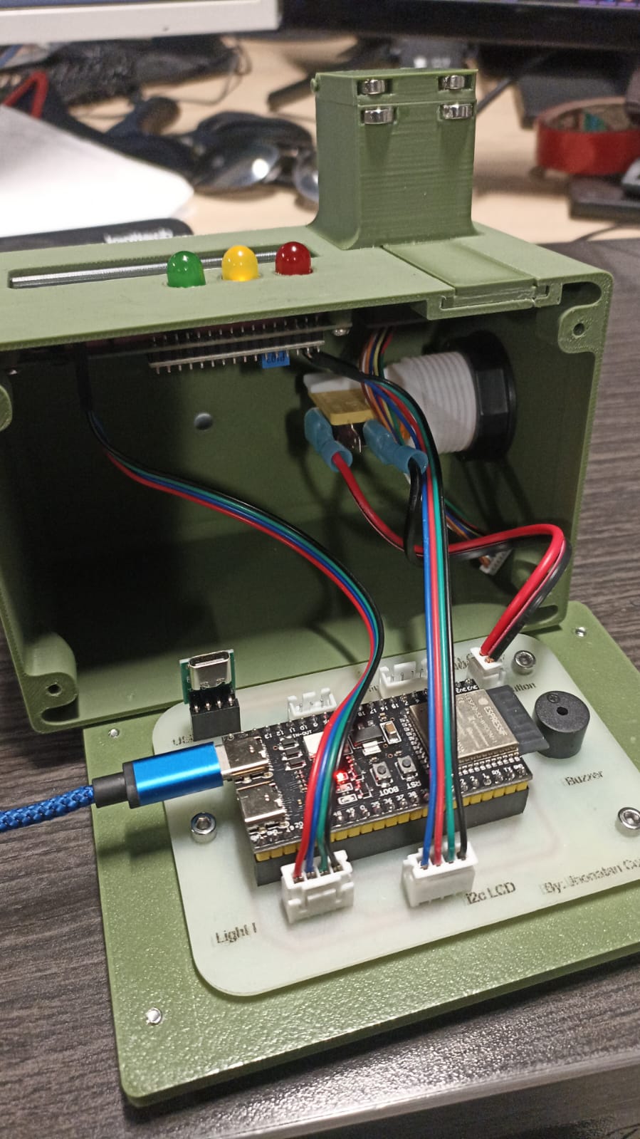
- 3D printed base: holds the custom PCB and ensures firm positioning of the ESP32-S3 and connectors.
- Laser-cut acrylic panel: provides protection for the display while offering visibility and a professional finish.
- Crimped cables with JST connectors: enable quick and secure connections between modules, reducing wiring errors and improving durability.
This approach replaces temporary solutions such as breadboards or jumper wires, making the project look like a nearly finished product and ensuring greater mechanical and electrical reliability.
3D printed base with embedded custom PCB
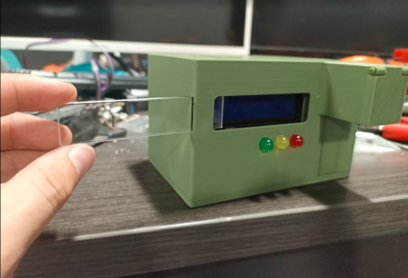
Laser-cut acrylic panel for LCD protection
Side view of the packaged system

Custom crimped cables with JST connectors
📽️ Packaging Process Overview
Short demo showing how the components are assembled and packaged
🔩 Case Assembly Steps
Assembling the final enclosure required a methodical step-by-step process to ensure all components were correctly installed, secure, and accessible for maintenance or testing.
- Prepare all cables and connectors: Before anything was mounted, I crimped all the JST connectors and verified their length and orientation. Each cable was color-coded and kept at just the right length to avoid excess slack while allowing enough room for flexible routing.
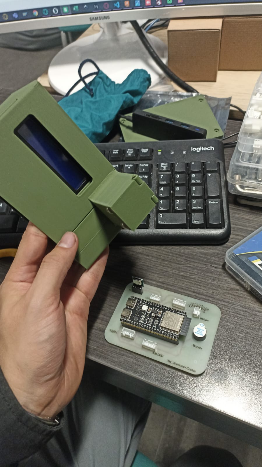
📷 PCB and enclosure lid prepared before mounting
- Mount the PCB to the enclosure lid: The PCB was secured onto the acrylic lid using screws and spacers. This setup allows the display to remain visible through the laser-cut window and provides a stable platform for all connections.
📷 Beginning the connection process for each component
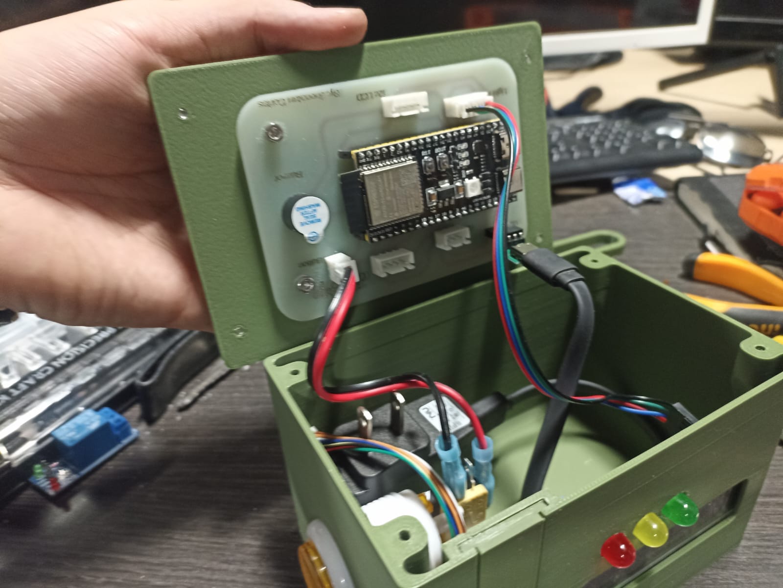
- Install all components and complete wiring: Once the PCB was secured, I proceeded to mount all internal components in their final positions. Each connection was made using uniquely shaped JST connectors to avoid plugging mistakes. Labels on the PCB helped identify where each wire should go. The last components to connect were the relay and power supply, as they are tied to the machine’s mains power.

📷 Most of the components connected and aligned inside the case
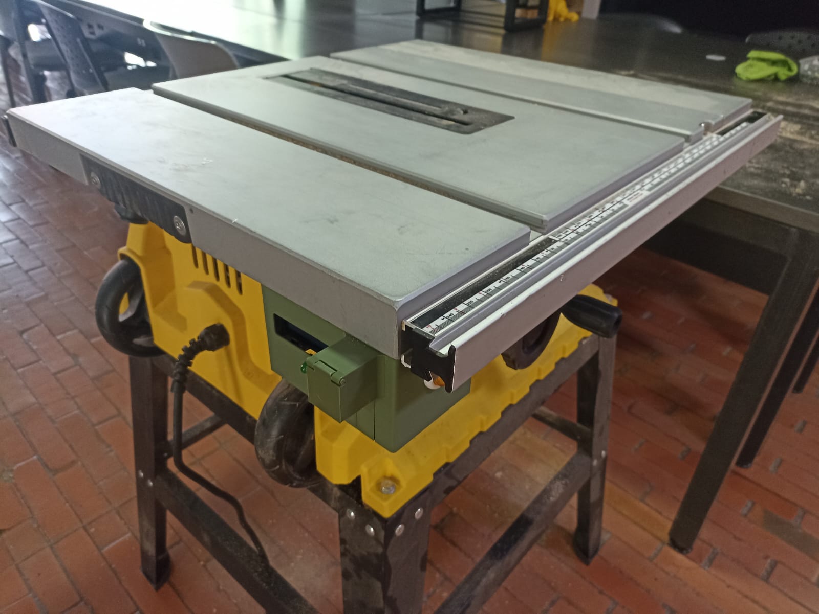
- Secure the relay and power supply: These two were placed in specific locations inside the enclosure. The relay was mounted so that it could also be fastened through the same screw that holds the enclosure to the machine — this minimized hardware and ensured mechanical stability.
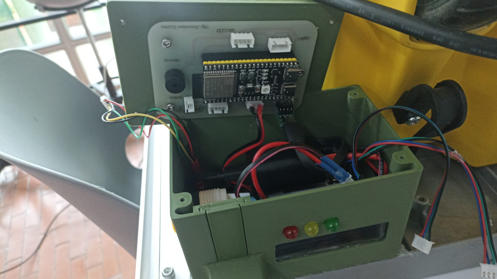
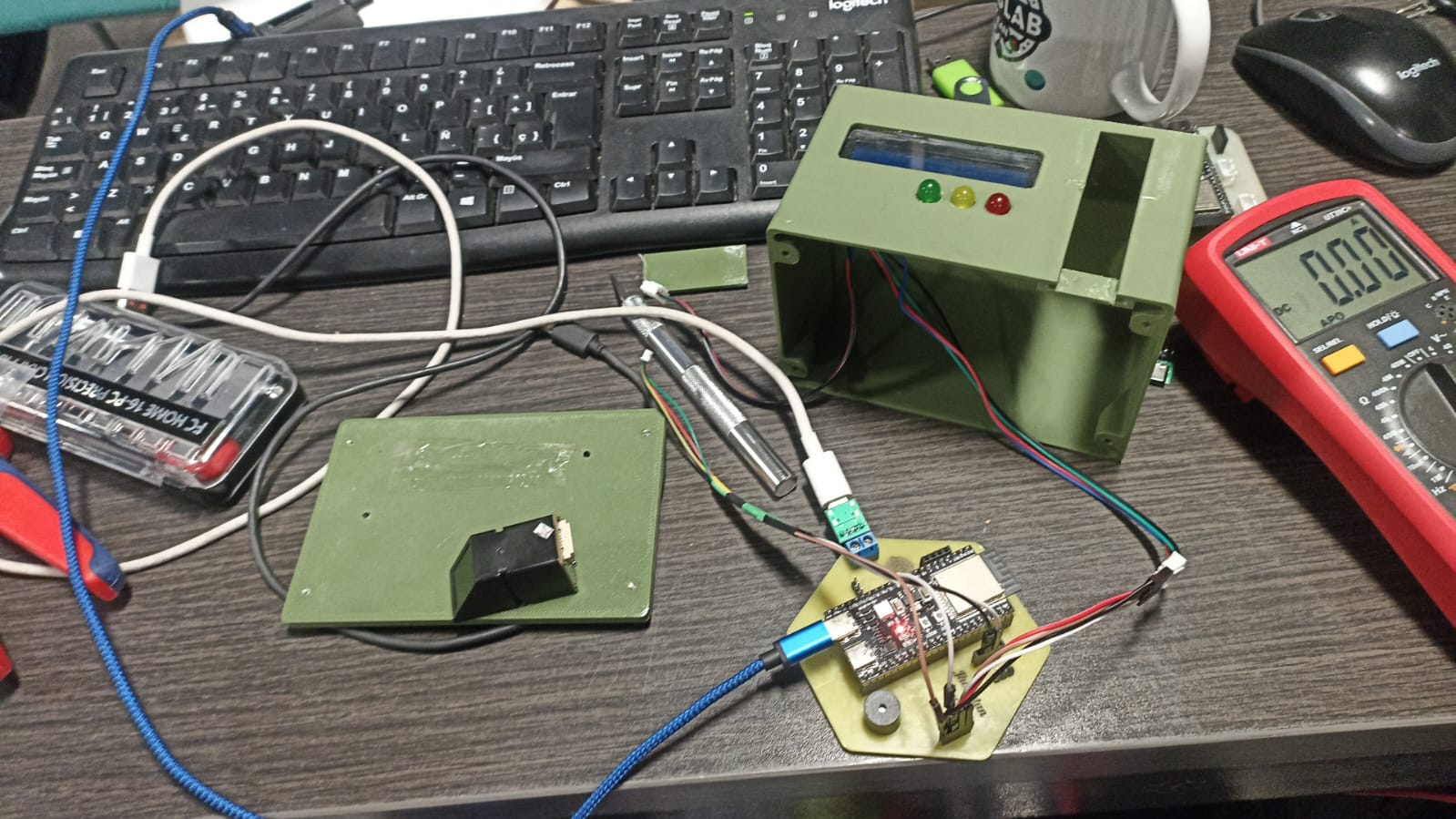
📷 Final installation — case mounted with components and cables in place
- Close and seal the enclosure: Finally, once all cables were tested and secured, I screwed the enclosure lid into place. This step completed the mechanical integration and protected the internal electronics from dust and accidental contact.
The final result is a clean, compact, and robust system where every component is easy to access and replace if needed. The use of modular connectors and internal routing strategies helps maintain functionality while giving the project a polished, product-like appearance.
2. Designed Final Project to Look Like a Finished Product
As part of the system integration process, I focused on assembling my project with a professional and product-like finish. While I did not label individual cables, I ensured that all internal wiring was carefully routed, covered, and secured within the enclosure.
The electronics were mounted on a custom 3D-printed base, and a laser-cut acrylic panel was used to protect the display. Cable lengths were optimized to avoid excess, and each wire was placed in a stable position, minimizing movement and preventing mechanical stress. This approach contributes significantly to the reliability, safety, and aesthetics of the final build.
As a result, the project now looks and behaves like a finalized product, not just a prototype. The internal organization and casing allow it to be handled, tested, and potentially deployed in real-world environments.
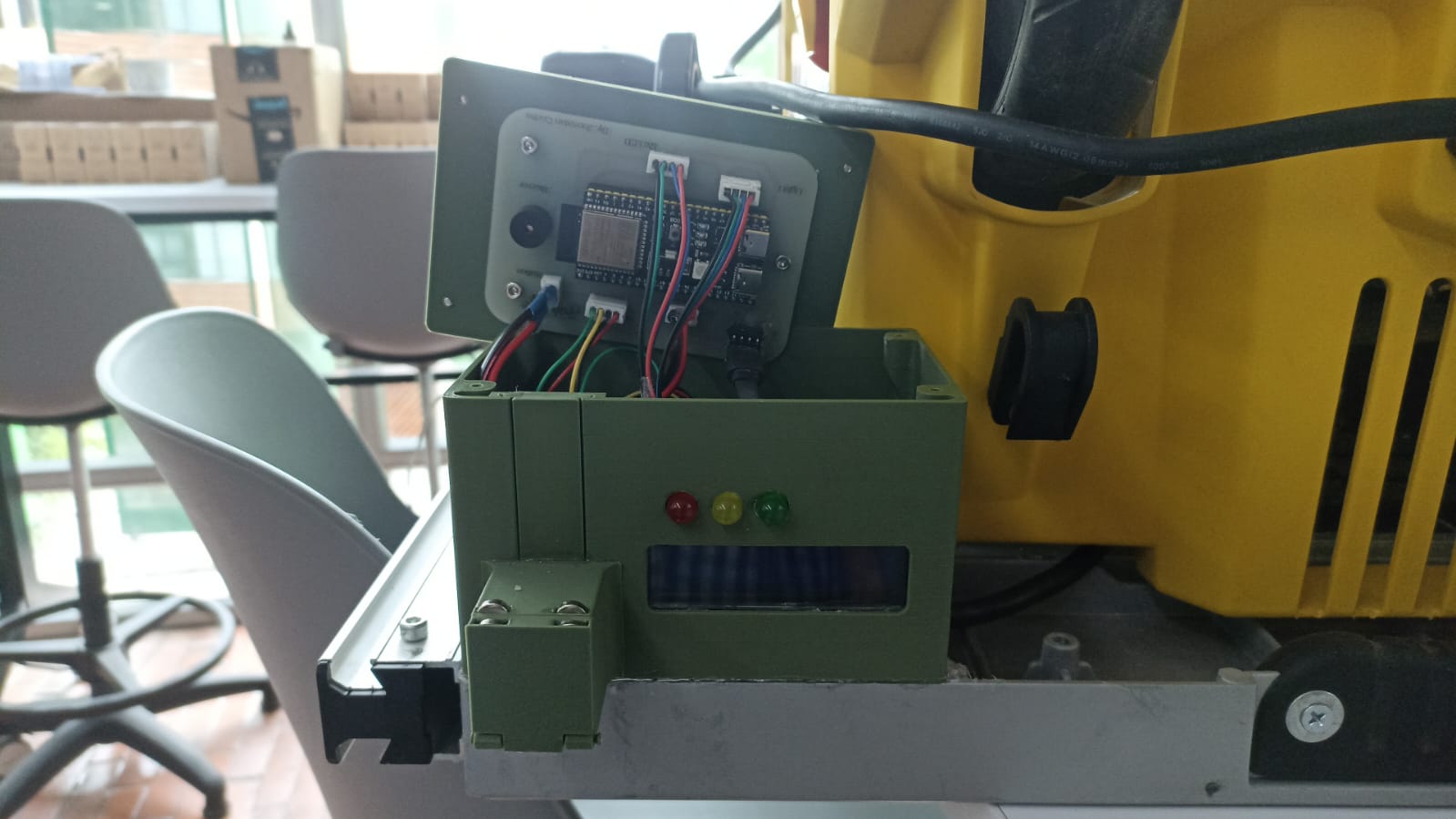
All cables routed and fixed within the case
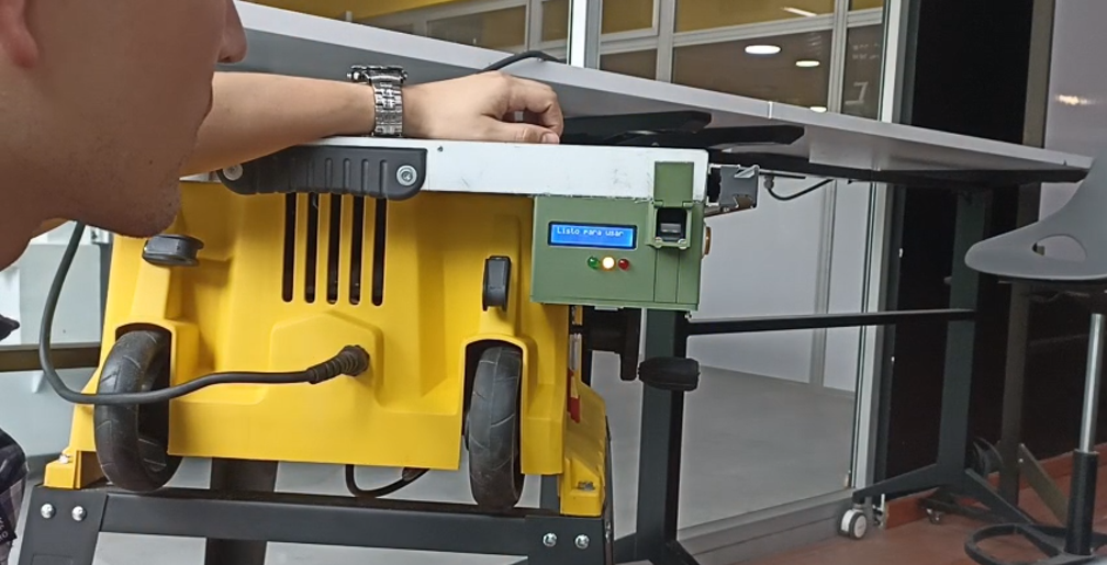
Enclosure closed and system ready to operate
🎥 Final Assembly Overview
Video showing how the components fit together inside the finished case
3. Documented System Integration of Final Project
After developing and testing each part of the system individually in previous weeks, I dedicated this stage to integrating all subsystems into one unified, working project. This involved combining the hardware, software, and mechanical structure to function together reliably.
The final system is powered by an ESP32-S3 microcontroller, which acts as the brain of the project. It controls and coordinates:
- Fingerprint module: validates user identity and grants or denies access.
- Relay and power system: cuts or restores power to the connected machine based on access control logic.
- RGB LED traffic light: indicates system state visually (red for blocked, green for active, yellow for warning/emergency).
- LCD display: shows real-time messages and instructions to the user.
- Buzzer: provides audio feedback during alerts or errors.
- Emergency stop button: forces a system shutdown for safety.
All these components are connected to a custom PCB with JST crimped cables and placed securely inside a 3D-printed and laser-cut case. The ESP32 firmware manages the interaction logic using modular programming and state control.
During integration testing, I verified that every input triggered the expected behavior and that the system could handle sequences like authentication → activation → timeout → reset smoothly. Edge cases, such as invalid fingerprints or emergency stops, were also tested and responded correctly.
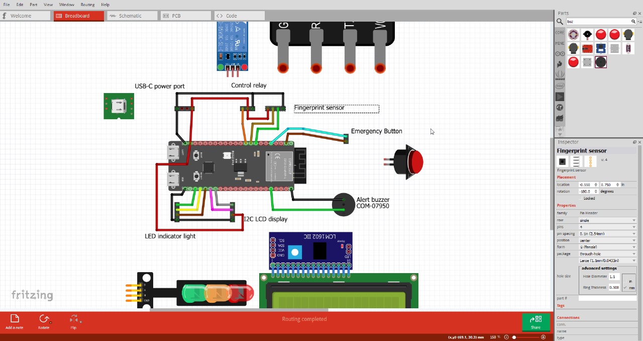
Diagram showing how all components interact within the system
🎥 Full System Integration Demo
Video showing full operation of the integrated system, including authentication, timing, alerts and shutdown
🧪 Troubleshooting & Testing Summary
During the integration phase, I spent several hours testing each component individually to ensure stability and proper interaction. I started by isolating the peripherals to validate their behavior:
- 🟢 Connected the RGB LED and triggered basic color changes from the ESP32-S3
- 🔔 Tested the buzzer with a push button to confirm tone triggering
- 📟 Displayed test messages on the LCD such as “System Ready” and “Button Pressed”
- 🔌 Verified the relay activation through manual control to confirm it could handle load switching properly
📷 Relay test connected directly to the ESP32-S3 — confirmed working with digital logic
I also double-checked the wiring of all critical components. Cable lengths were adjusted, connections reviewed, and labels verified to reduce the risk of mismatches or false contacts during the final assembly.
📷 Validating cable order, pin headers, and JST crimps before final integration
The biggest issue I encountered was related to the fingerprint sensor. Although it initially worked during early tests, it began to fail after several readings. Sometimes it froze, other times it sent corrupted data, or even caused the ESP32 to crash.
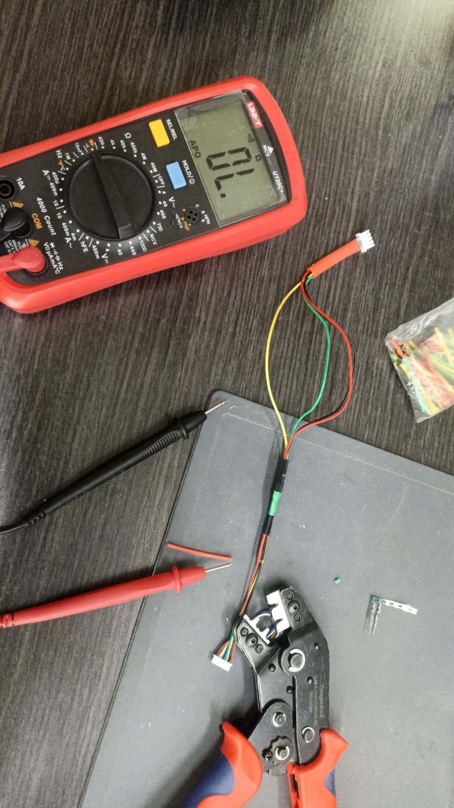
I spent a lot of time diagnosing the problem — consulting forums, technical documentation, and AI tools — and eventually moved to electrical validation using a multimeter to discard voltage drops or short circuits.
📷 Measuring voltage from the fingerprint sensor — confirming power levels and stability
After several hours of testing and isolating components, I discovered that frequent continuous readings caused the fingerprint module to overheat. This overuse destabilized not only the sensor, but the entire MCU. To solve it, I:
- 🧠 Modified the code to limit the read frequency and introduce cooldown intervals
- 🔌 Powered the sensor from an external regulated 5V source to reduce stress on the board
- 📟 Added screen messages to indicate read timeouts and sensor rest states
This real-world debugging taught me a lot about sensor limitations, thermal behavior, and how important it is to simulate extended use scenarios. With these changes, the fingerprint module now works reliably as part of the integrated system.
🧠 Code Structure: Admin Mode and Operational Mode
To maintain clarity and modularity, the system uses two separate codes, each with a specific purpose:
🔐 1. Admin Mode – Fingerprint Registration System
This version of the code activates a local WiFi Access Point generated by the ESP32-S3. When triggered (e.g., by pressing a button for 2 seconds), the board opens a basic web server, allowing the administrator to:
- View the list of stored fingerprints (with optional names)
- Register new fingerprints through a guided interface
- Delete specific fingerprints directly from the browser
No login page is required; security is based on a hidden SSID and password for the admin AP, ensuring only authorized personnel can connect.
⚙️ 2. Operational Mode – Final System Behavior
This version is used during normal machine operation. The ESP32-S3 controls all components based on user interaction and safety logic:
- When a valid fingerprint is detected: the system activates, turns the LED green, and powers the relay for a limited time (5 min).
- If an invalid fingerprint is scanned: the buzzer sounds, the LED turns red, and after 3 failed attempts the system locks for safety.
- If the emergency stop button is pressed: the relay is shut down, an alert is triggered, and the screen displays a countdown before reset.
- If time expires: the relay and green light are turned off and the system returns to standby mode.
The code is divided into modular functions for clarity and easier debugging, covering fingerprint handling, screen updates, LED/buzzer control, and timing logic.
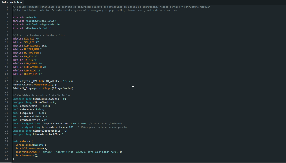
Code architecture separating admin and operational logic for better system management
4. Linked to Final Project Page
All the documentation shown here, including packaging methods, final assembly, system logic, and integration testing, is also part of the complete development of my Final Project. This content supports the full understanding of how the project evolved from idea to execution.
The integration process not only validates the individual components and code but also confirms that the final product is reliable, safe, and functional under real use conditions. The details, code files, diagrams, videos, and documentation are available through the link below.