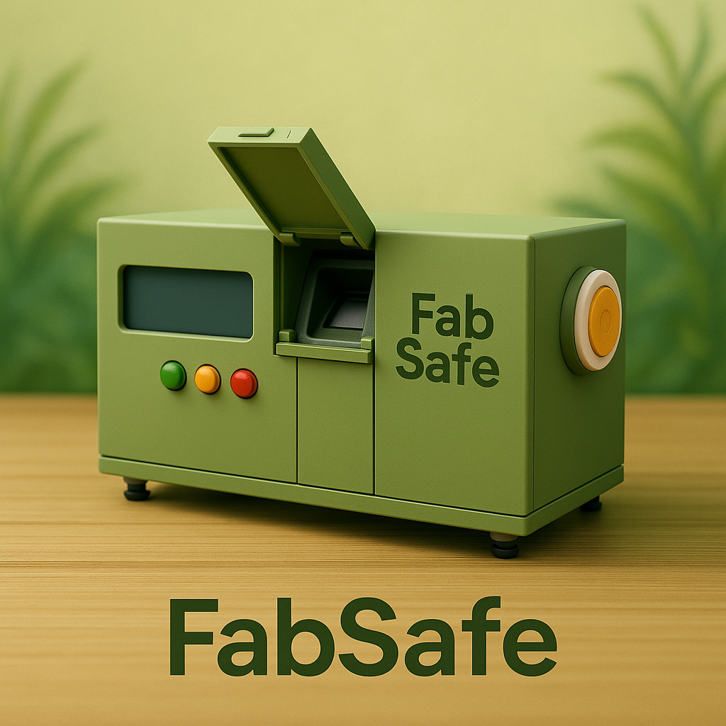
FabSafe
🎥 Final Presentation Video
presentation.mp4 – Full demo of FabSafe integration
📊 Final Presentation Slide
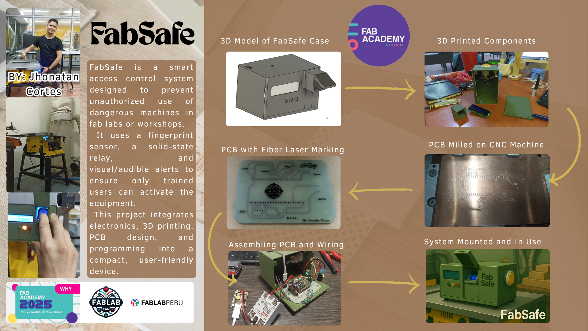
presentation.png – Slide resumen del sistema FabSafe
Protecting hands, minds, and futures – because safety comes before innovation.
Where the Idea Was Born: First Sparks of FabSafe
The concept for FabSafe emerged during early Fab Lab sessions when I noticed how easy it was for anyone — experienced or not — to access high-risk machines like the table saw without supervision. It made me think: What if a simple, smart access system could reduce accidents and encourage responsibility? That’s how FabSafe began — as a safety-first approach to shared innovation environments.
FabSafe © 2025 by Jhonatan Cortes is licensed under Creative Commons Attribution-NonCommercial-ShareAlike 4.0 International
What is FabSafe?
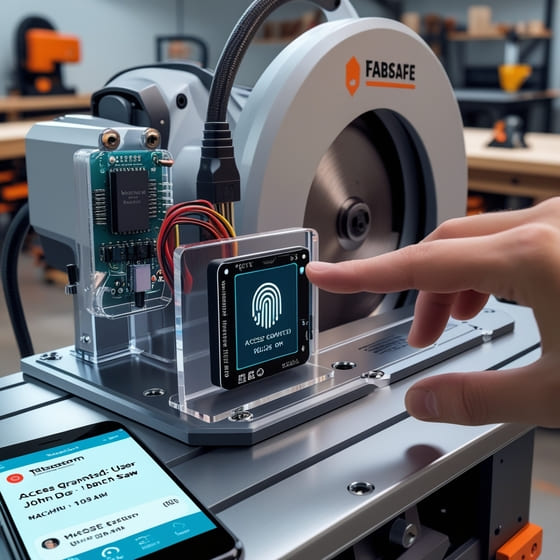
FabSafe is a security and access control system designed for high-risk equipment in Fab Labs. Its main goal is to promote safe, authorized use of dangerous tools such as table saws, laser cutters, and CNC machines.
The system uses a fingerprint sensor to identify users and controls machine power through a solid-state relay (SSR). This ensures that only trained individuals can activate the tool.
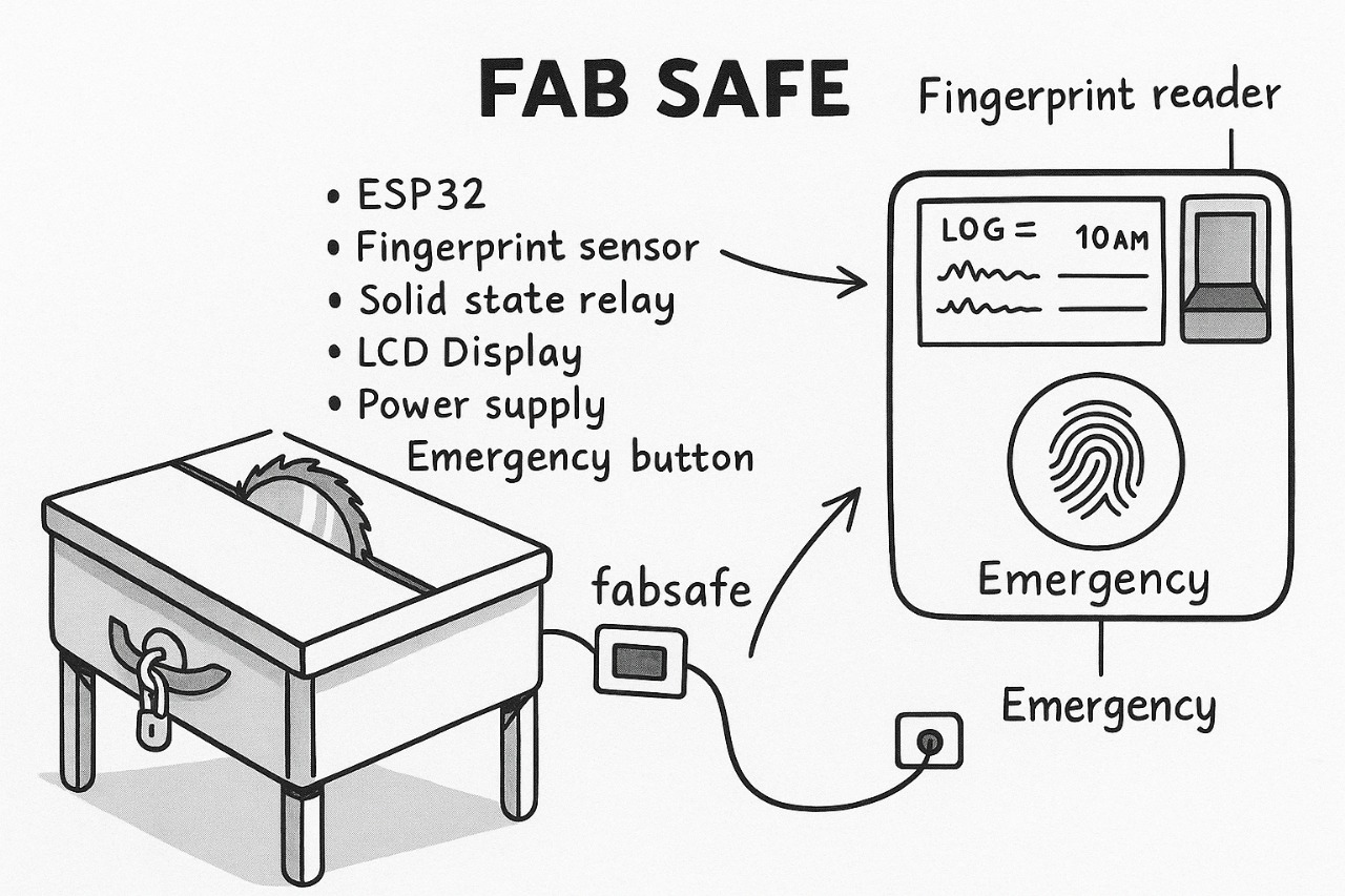
Core Components
- ESP32-S3 microcontroller: chosen for its processing power, wireless capabilities, and scalability for future integrations.
- Fingerprint reader: authenticates users locally before enabling the machine.
- Solid-state relay: safely powers the tool only when authorized.
- Emergency stop button: immediately cuts power in critical situations.
- LCD screen: displays status messages, feedback, and alerts.
- Countdown timer: deactivates the machine automatically after 5 minutes of use or inactivity.
Design Choices & Evolution
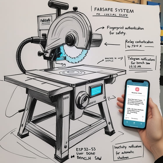
During development, I considered including Telegram notifications to send access logs to administrators. However, after discussing with instructors, I decided to focus on reliability and core local features, keeping the system efficient and easier to maintain. Advanced features may be added in the future.
Why It Matters: Key Benefits
- ✔️ Safety: Prevents unauthorized use of dangerous tools.
- ✔️ Control: Tracks machine access and session time.
- ✔️ Accident prevention: Includes emergency stop and inactivity timer.
- ✔️ Admin access: System configuration and fingerprint management via WiFi AP mode.
- ✔️ Scalability: Can be adapted to other machines or labs easily.
Component Cost Overview
The following table summarizes the main components used in FabSafe, including their quantity, individual cost, and total budget estimation.
Based on estimated prices from Amazon, the total cost of all required components is approximately $113.76 USD. This estimation assumes the use of only one unit per item and includes essential electronic, mechanical, and structural elements. Most materials were already available at the Fab Lab, reducing the real production cost.
| Component | Description | Used For | Price (USD) |
|---|---|---|---|
| ESP32-S3 DevKit | Main microcontroller that handles fingerprint validation and device control | Embedded programming, Wi-Fi sync, relay control | $9.99 |
| R307 Fingerprint Sensor | Biometric sensor to authenticate user access | Security and access control | $19.18 |
| LCD 16x2 Display (I2C) | Alphanumeric display to show system status and instructions | User interface output | $9.99 |
| Solid State Relay (40A) | Controls power to the machine safely and reliably | Power switching and machine control | $9.98 |
| Mini Traffic Light Module | 3-color LED module to indicate system states | Visual feedback | $4.49 |
| Buzzer (10-pack) | Audible alert when access is denied or system is triggered | Sound feedback | $5.99 |
| 5x LED Arcade Buttons | Used for emergency stop and potential manual controls | User input / stop button | $11.18 |
| JST-XH Connector Kit | Set of connectors and pins for modular wiring | Cabling and modular connections | $9.99 |
| PLA Filament (1kg) | 3D printing material for the system enclosure | 3D printed case | $18.99 |
| Acrylic Sheets (5"x7") | Transparent cover to protect the display and components | Laser-cut protector | $5.59 |
| PCB FR4 Boards (5-pack) | Boards used to fabricate the custom PCB layout | Electronics production | $4.39 |
| Jumpers & handmade cables | Cables for internal wiring and testing | Wiring and connections | $4.00 |
| Total Estimated Cost | $113.76 | ||
Mid Term Review – FabSafe Project
From concept to confirmation: tested functionalities and a clear plan toward final execution.
1).✅ Confirmed Functionalities
The following core features have been tested and confirmed. Each function was validated through controlled trials and real-use simulations, ensuring the system behaves as expected before final assembly.
| Functionality | Description | Validated By |
|---|---|---|
| Fingerprint recognition | Only authorized users can activate the machine | ✅ Fingerprint test (video & logs) |
| Unauthorized attempt rejection | Denies access to unregistered fingerprints | ✅ 3 invalid scan lockout |
| Emergency stop | Immediate power cut-off via hardware button | ✅ Button tested manually |
| Auto timeout | Machine turns off after 5 minutes of inactivity | ✅ Countdown successfully tested |
| Admin AP Mode | WiFi interface to register fingerprints securely | ✅ Web interface in Access Point mode |
| Visual & audio feedback | LCD messages, buzzer tones, and LED indicators | ✅ System response observed |
| Relay control | Solid-state relay powers machine only when authorized | ✅ Relay toggled after fingerprint check |
2).🧩 Project Workflow Overview
This diagram illustrates the major phases of the FabSafe project, including design, production, integration, and testing.
This roadmap summarizes the complete development workflow of the FabSafe project, from design to deployment.
Design & Prototyping
- ✔ 2D Design (LCD Shield)
- ✔ 3D Printed Case (LCD, Fingerprint, Buzzer)
- ✔ Laser-cut acrylic screen protector
Electronics Fabrication
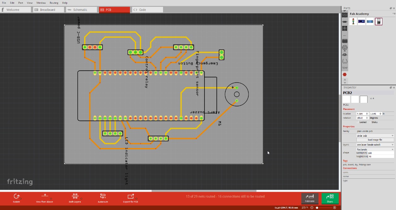
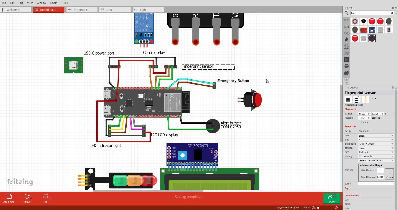
- ✔ PCB Design (Fritzing)
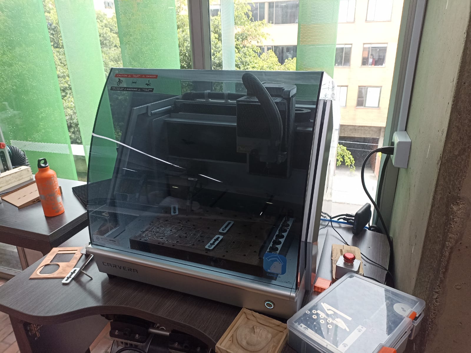
- ✔ PCB Milling (CNC FabLab)
- ✔ Manual Soldering & Connectors
Firmware Development
- ✔ Core System Logic
- ✔ Emergency & Access Protocols
- ✔ AP Web Interface for Admin
Hardware-Software Integration
- ✔ Fingerprint + LCD + Relay Sync
- ✔ Multicomponent Wiring
- ✔ Real-Time Activation
Field Testing
- ✔ Functional Tests in FabLab
- ✔ User Authentication Checks
- ✔ Emergency Scenarios
Project Documentation
- ✔ Weekly Logs
- ✔ Final Report (in progress)
- ✔ Video & Presentation Slides
3).📆 Project Timeline & Progress
A visual breakdown of tasks completed and upcoming, organized week-by-week with estimated delivery dates.
Project Timeline & Progress
| Phase | Start | End | Status |
|---|---|---|---|
| 2D Design (screen shield) | May 01 | May 01 | Completed |
| 3D Design (main case) | May 02 | May 03 | Completed |
| 3D Design (sensor case) | May 04 | May 04 | Completed |
| PCB Design, fabrication & soldering | May 05 | May 07 | Completed |
| Wiring with connectors | May 08 | May 08 | Completed |
| Embedded programming | May 09 | May 10 | Completed |
| Web interface (AP mode) | May 11 | May 12 | Completed |
| Microcontroller interfacing | May 13 | May 17 | Completed |
| Cross-validation | May 18 | May 23 | Completed |
| Functional & FabLab tests | May 23 | May 25 | Completed |
| Security & documentation | May 26 | May 30 | Completed |
4).🧪 Component Gallery
These are the key components used to build the FabSafe system, each selected for its role in safety, control, or communication.
Components:
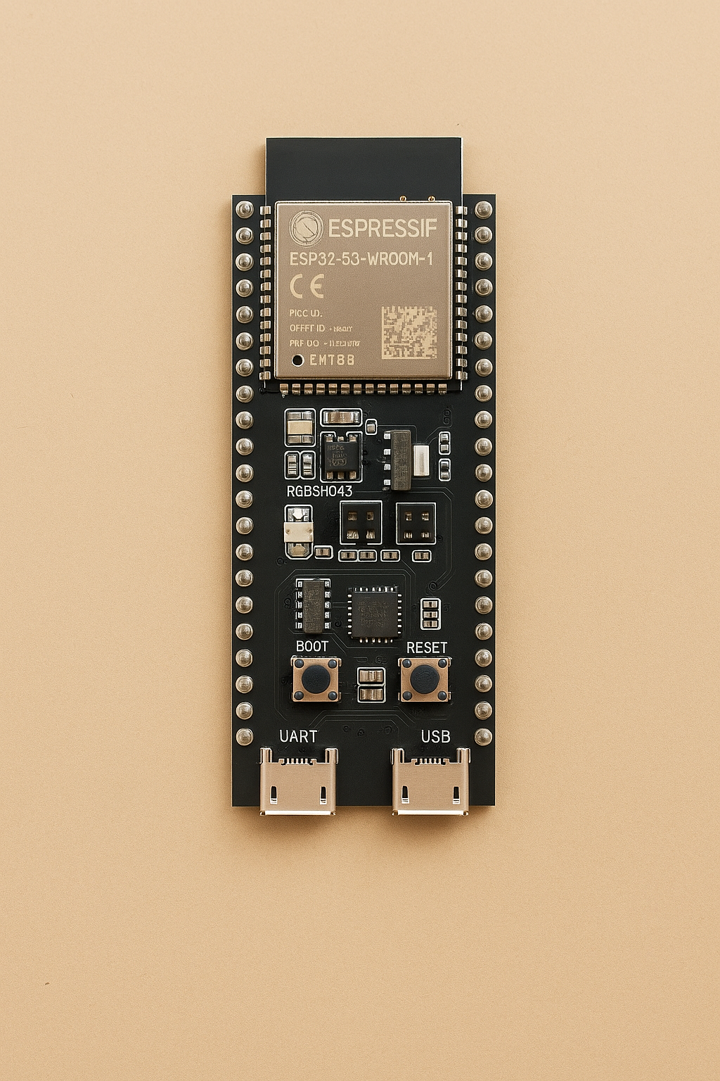
ESP32-S3
Microcontroller responsible for system logic and Wi-Fi communication.
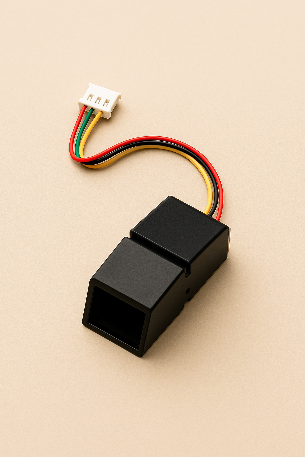
Fingerprint Sensor
Module R307 or FPM10A for user authentication through biometric scanning.
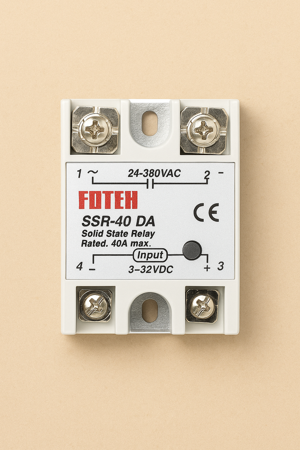
Solid State Relay (SSR)
Used to safely control the power supply of the machine.
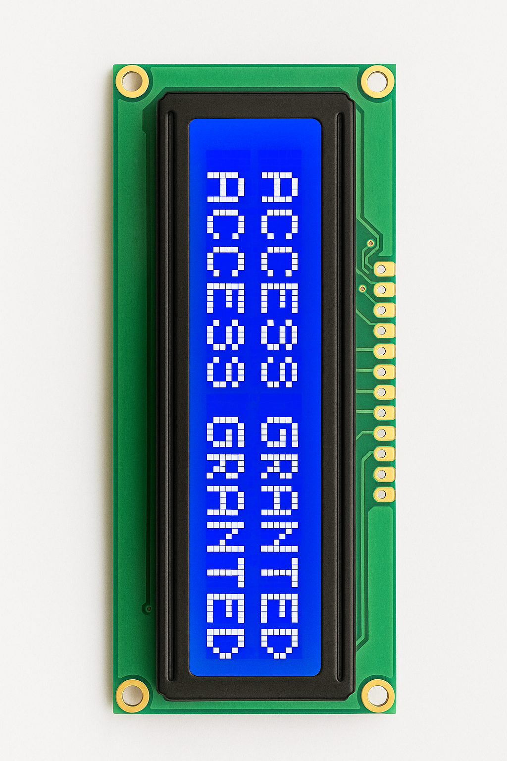
LCD Display (16x2)
Displays messages such as "Access Granted" or "Machine On".
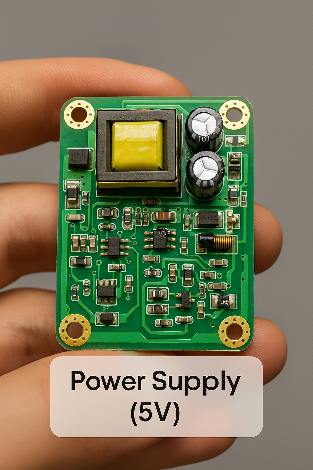
Power Supply (5V)
Recycled from a phone charger, used to power the ESP32, fingerprint sensor, and relay.
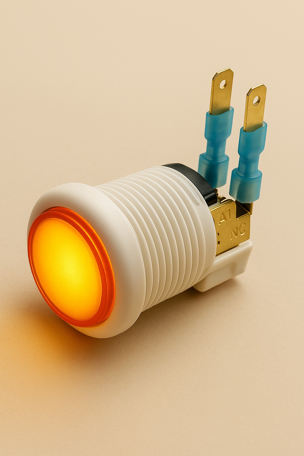
Emergency Button
Optional hardware button for immediate manual shutdown in case of emergencies.
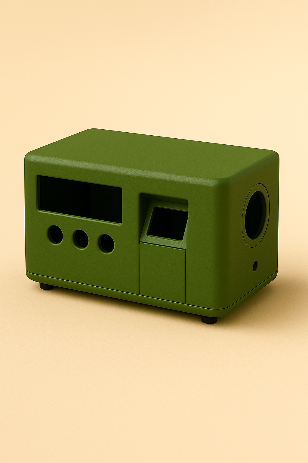
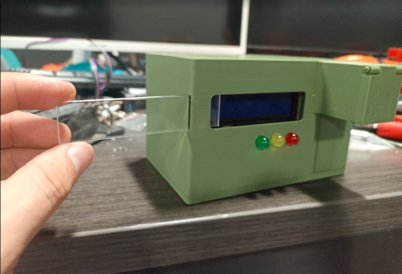
3D-Printed Enclosure
Custom-designed and 3D printed to protect components and provide a professional appearance.
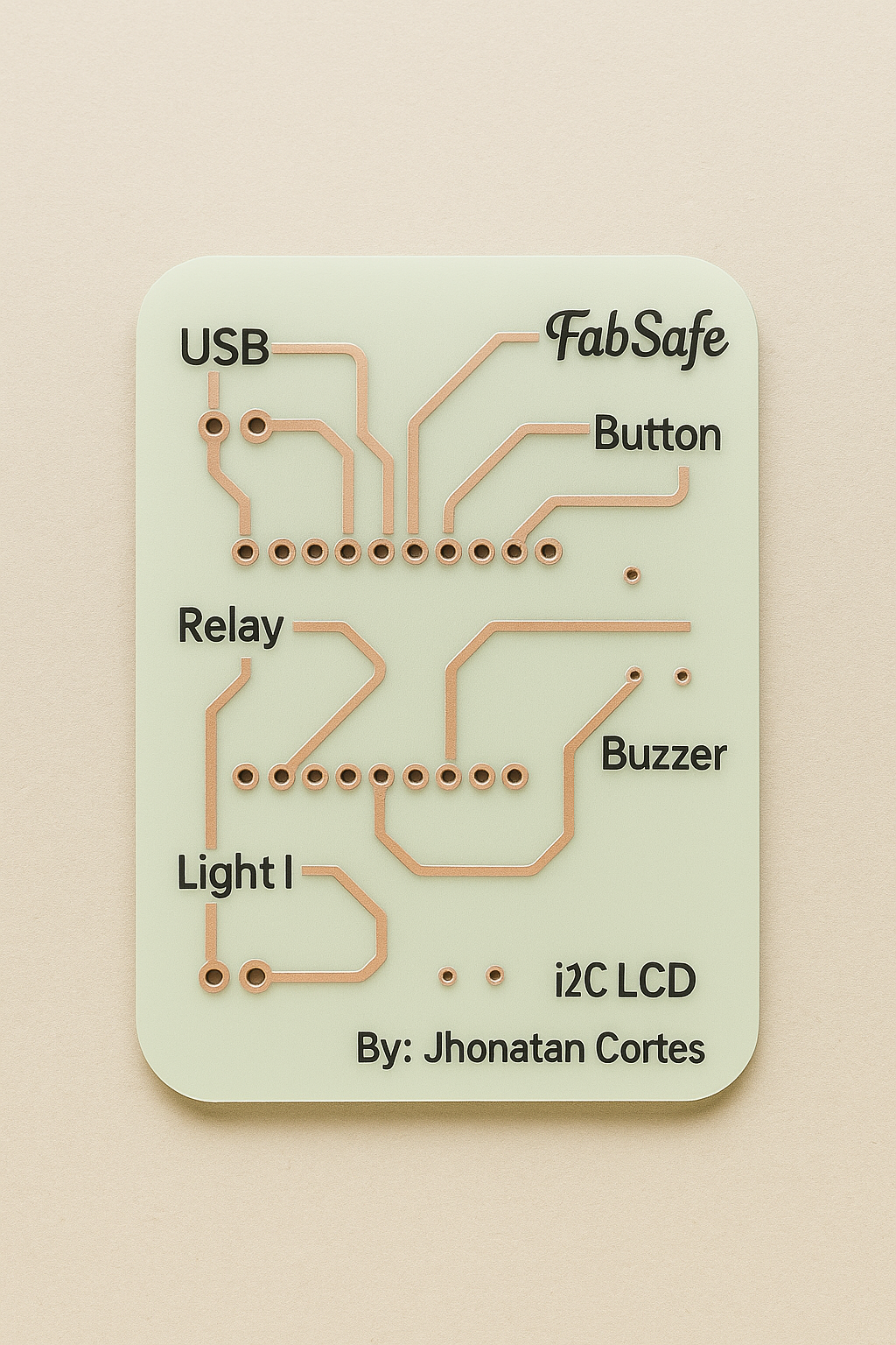
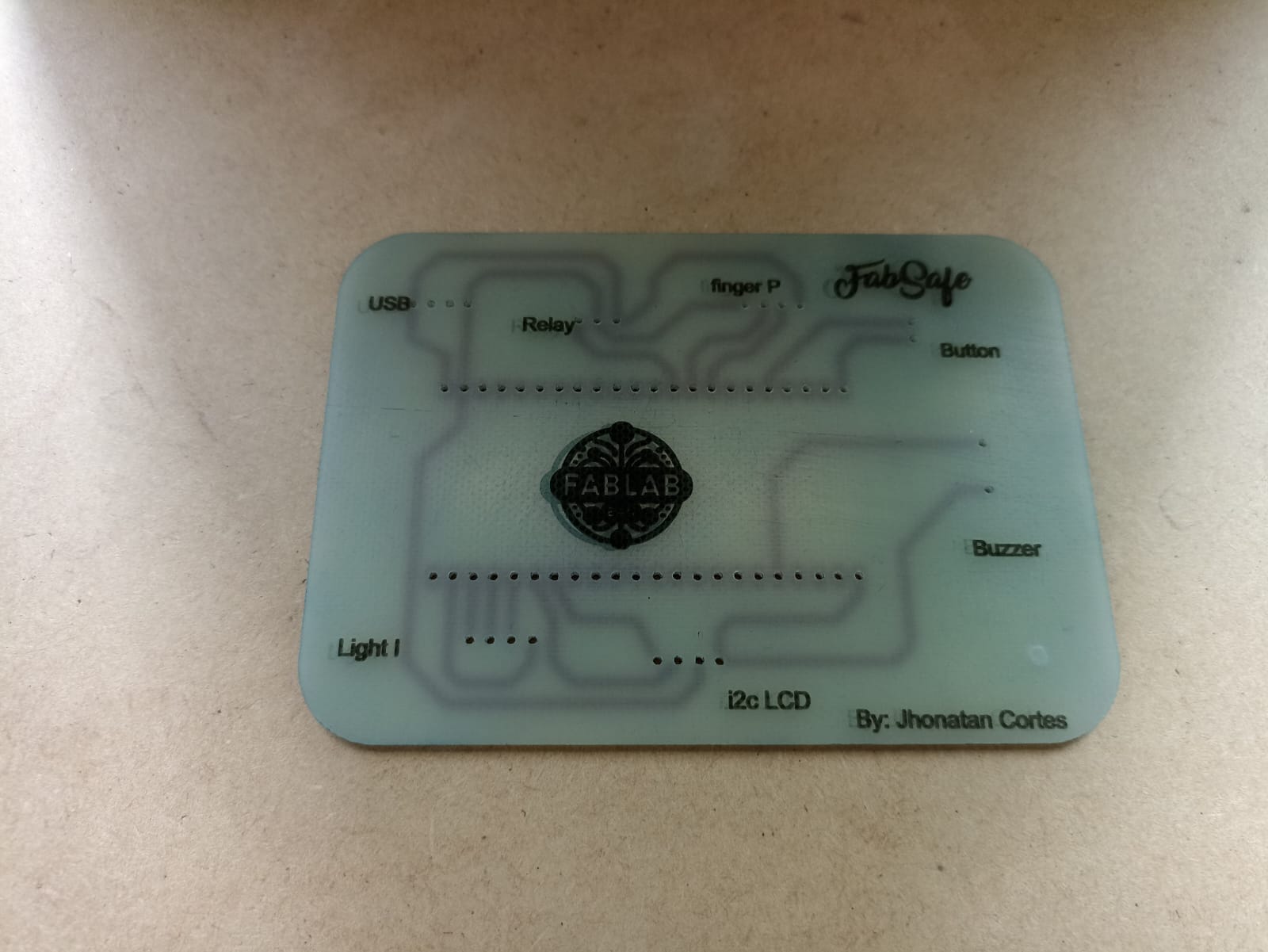
Custom PCB – FabSafe
This custom PCB was designed using Fritzing and fabricated with the FabLab's PCB milling machine.
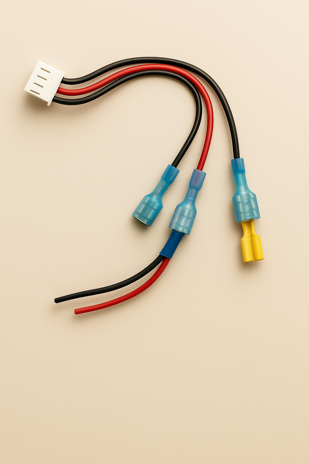
Custom Wiring & Connectors
Used throughout the prototyping phase, these hand-crimped connectors replaced traditional jumper wires.
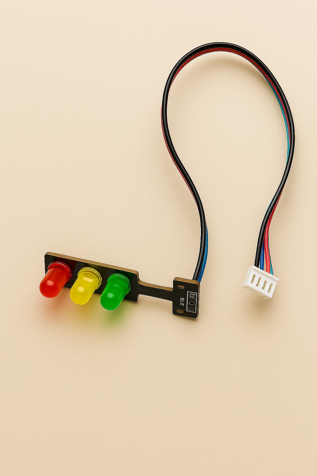
Mini Traffic Light Module
This 3-color LED module (green, yellow, red) provides visual feedback on the system state, helping users identify safe, warning, or blocked access modes at a glance.
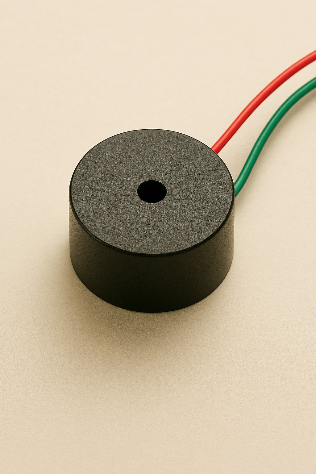
Buzzer Module
A compact audible buzzer is used to generate warning sounds when access is denied or the emergency mode is triggered, enhancing the system’s feedback with sound alerts.
5).📸 Real Progress So Far
Visual documentation of the development process, from early testing to functional prototypes. Each image highlights a key milestone.
Testing Fingerprint Module Connection
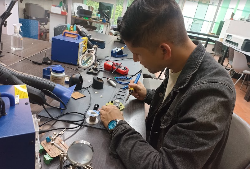
Manual Soldering of Final PCB
ESP32-S3 Mounting & Pin Alignment Check
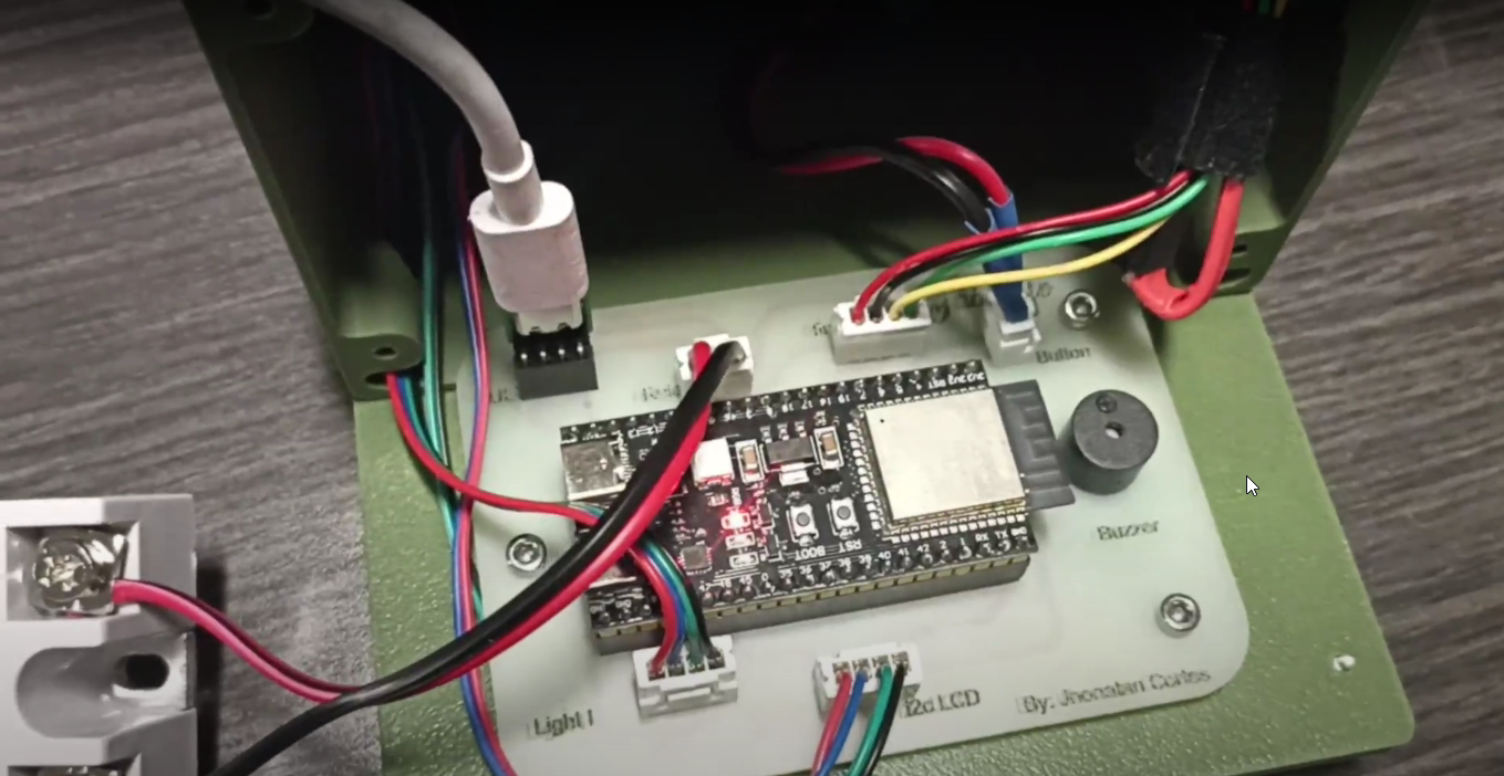
LCD + Buzzer + Relay Integration Test

WiFi Access Point Active – Admin Mode
Laser-Cut Acrylic Panel Fitted to Base
Project Timeline: FabSafe - Development by Phases
This section summarizes the journey of building FabSafe over the course of 3 months, structured into clear phases. Each step was carefully developed to create a working and safe biometric access system for high-risk machinery. Whether you're a beginner or an experienced developer, this is a guide to how it all came together.
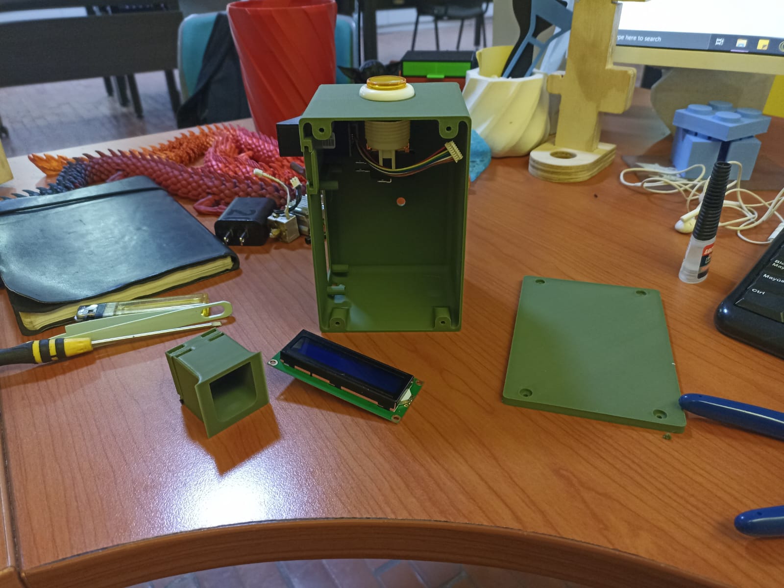
🧩 Phase 1: Design & Prototyping
The FabSafe journey began with a design challenge: How can we safely restrict access to a dangerous machine using low-cost and accessible tools? Using SolidWorks, we modeled a custom 3D-printed enclosure to house the entire system. The case was divided into functional zones:
- LCD display zone
- Fingerprint sensor mount
- Emergency stop button hole
- Port for a 3-color LED traffic module
- Speaker output for the buzzer
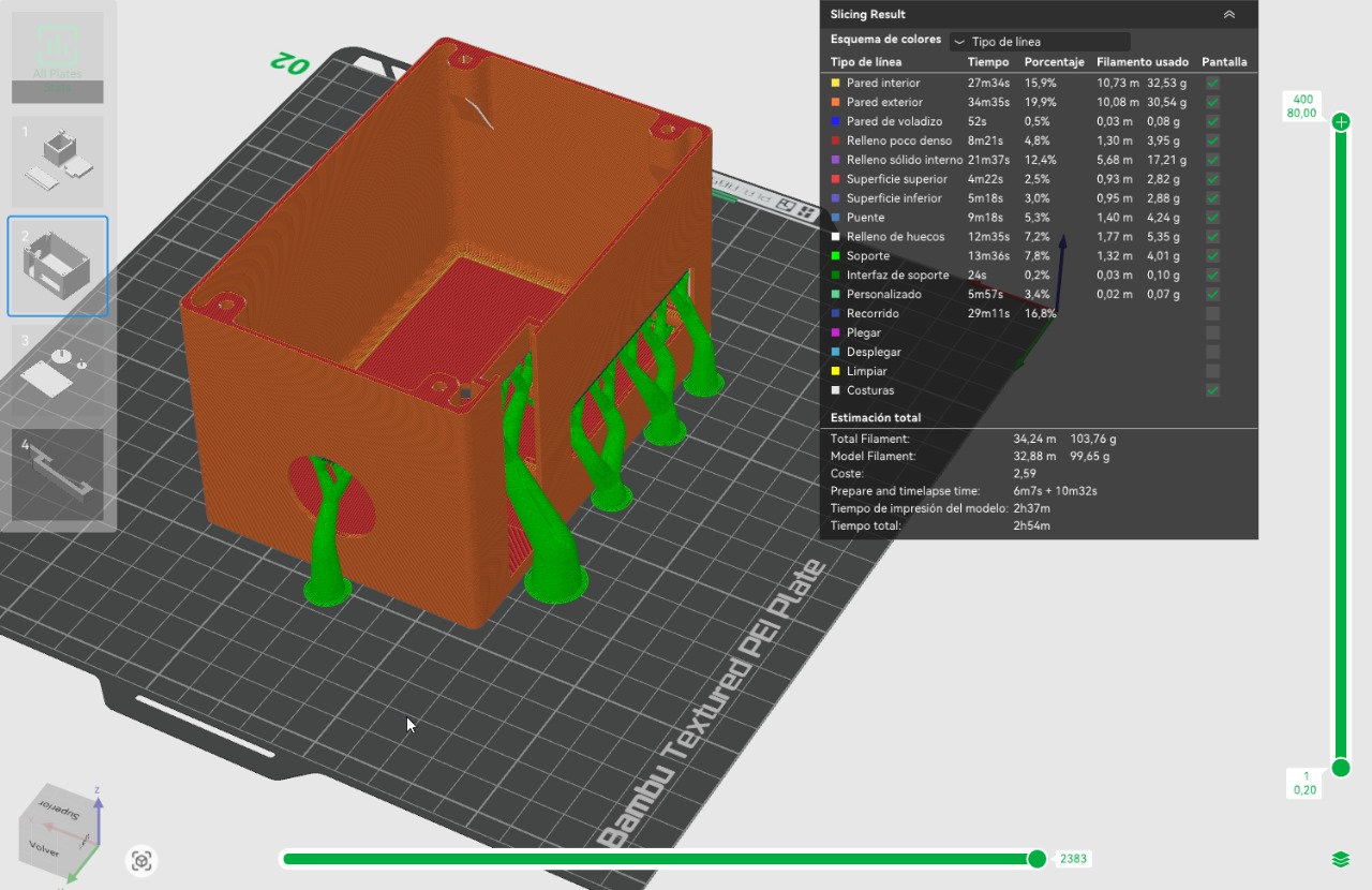
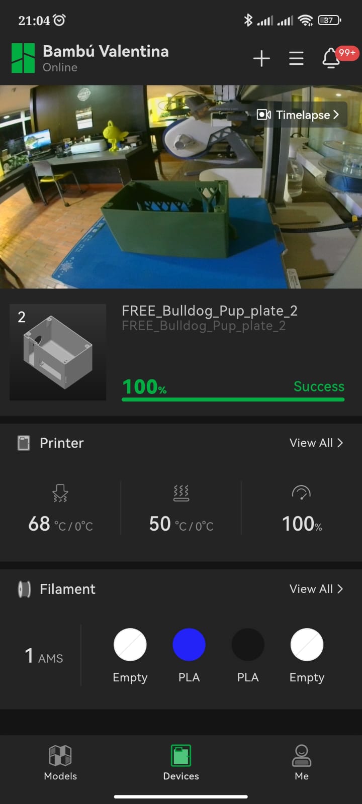
The prototype was printed on a Bambu Lab A1 using green PLA filament. The first print revealed design flaws: the hinges for the fingerprint lid didn’t align, and the sensor slot lacked support. We redesigned and reprinted the case with corrected geometry.
Meanwhile, we started the electronic setup using Fritzing to create a modular PCB. This board was milled using a desktop CNC machine in the FabLab and soldered by hand, including headers for modular connection of the ESP32-S3, LCD, relay, buzzer, and sensor. The result: a clean, scalable board.
⚙ Phase 2: Electronics Fabrication
Once the layout was set, we fabricated the PCB (Printed Circuit Board) using a single-sided copper plate. The board was milled using a FabLab PCB CNC machine and included silkscreen labeling for easy assembly. After milling:
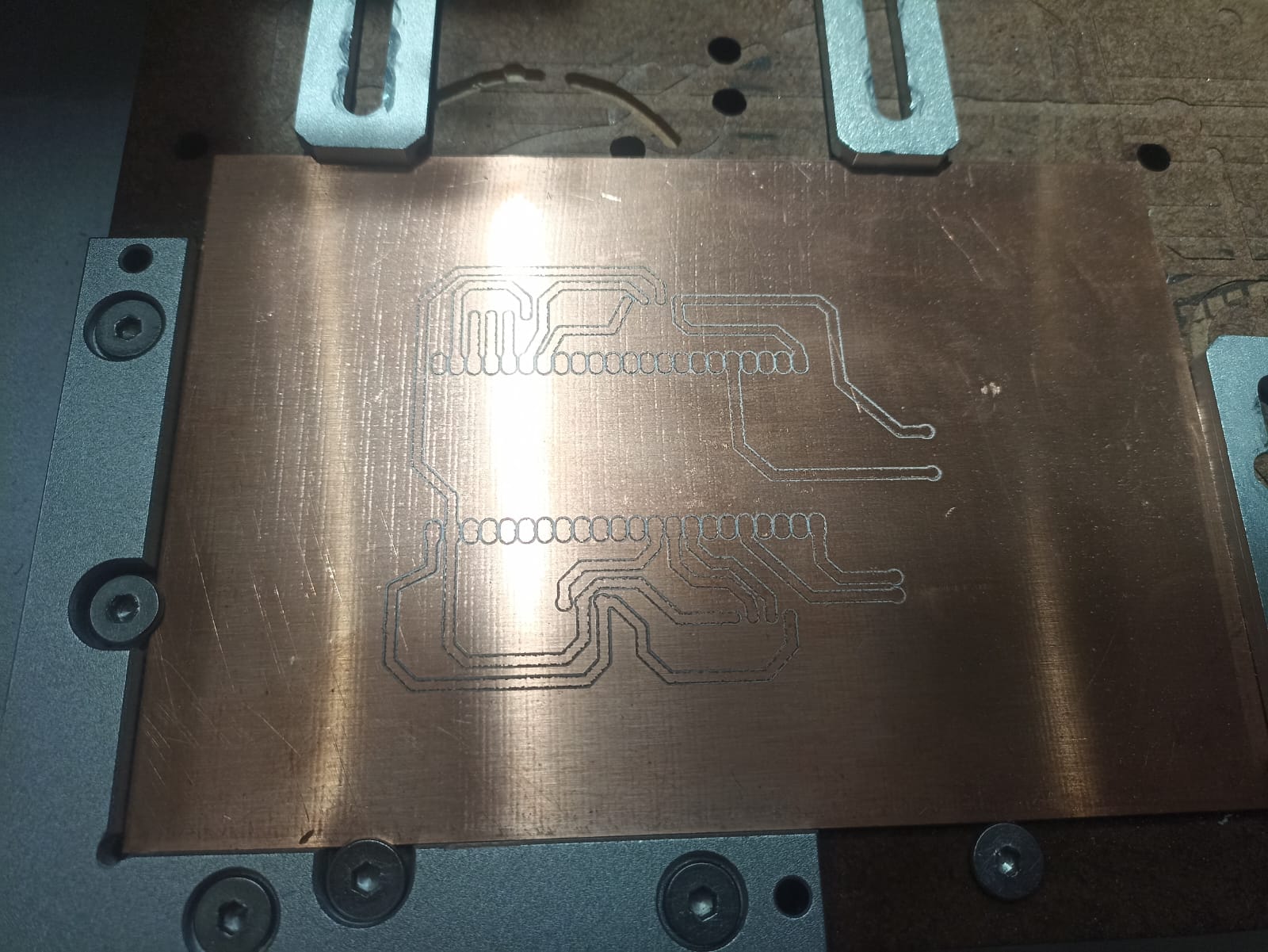
- We polished the copper tracks
- Manually soldered all headers and resistors
- Tested connections for continuity
For wiring, instead of standard jumper wires, we used hand-crimped JST connectors to ensure stability and replaceability. The relay was upgraded from 10A to 40A Solid State Relay after calculating the saw’s 1800W power draw.
Power was supplied using a recycled 5V phone charger and USB-C breakout board. This not only reduced cost, but allowed plug-and-play testing.
💻 Phase 3: Firmware Development
Programming began on the ESP32-S3, taking advantage of its dual-core processor. Early tests revealed that memory usage from the fingerprint and Wi-Fi libraries was a problem.
To solve this, we divided the system into two modes:
- Admin Mode: Starts in Access Point (AP) mode. Shows IP on LCD. A local web interface allows adding/removing fingerprints.
- Operation Mode: Only reads stored fingerprints and handles logic (timers, relays, emergency stop).
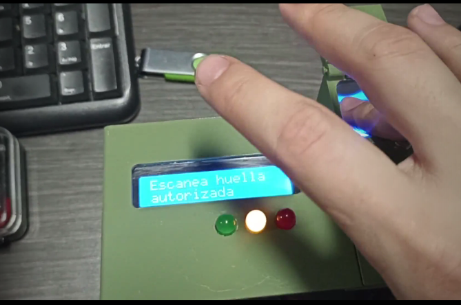
This approach allowed us to stay within memory limits while maintaining full control. The LCD showed status messages, countdowns, and alerts. A buzzer gave audible feedback. The LED traffic module showed system state (Red = Blocked, Yellow = Standby, Green = Active).
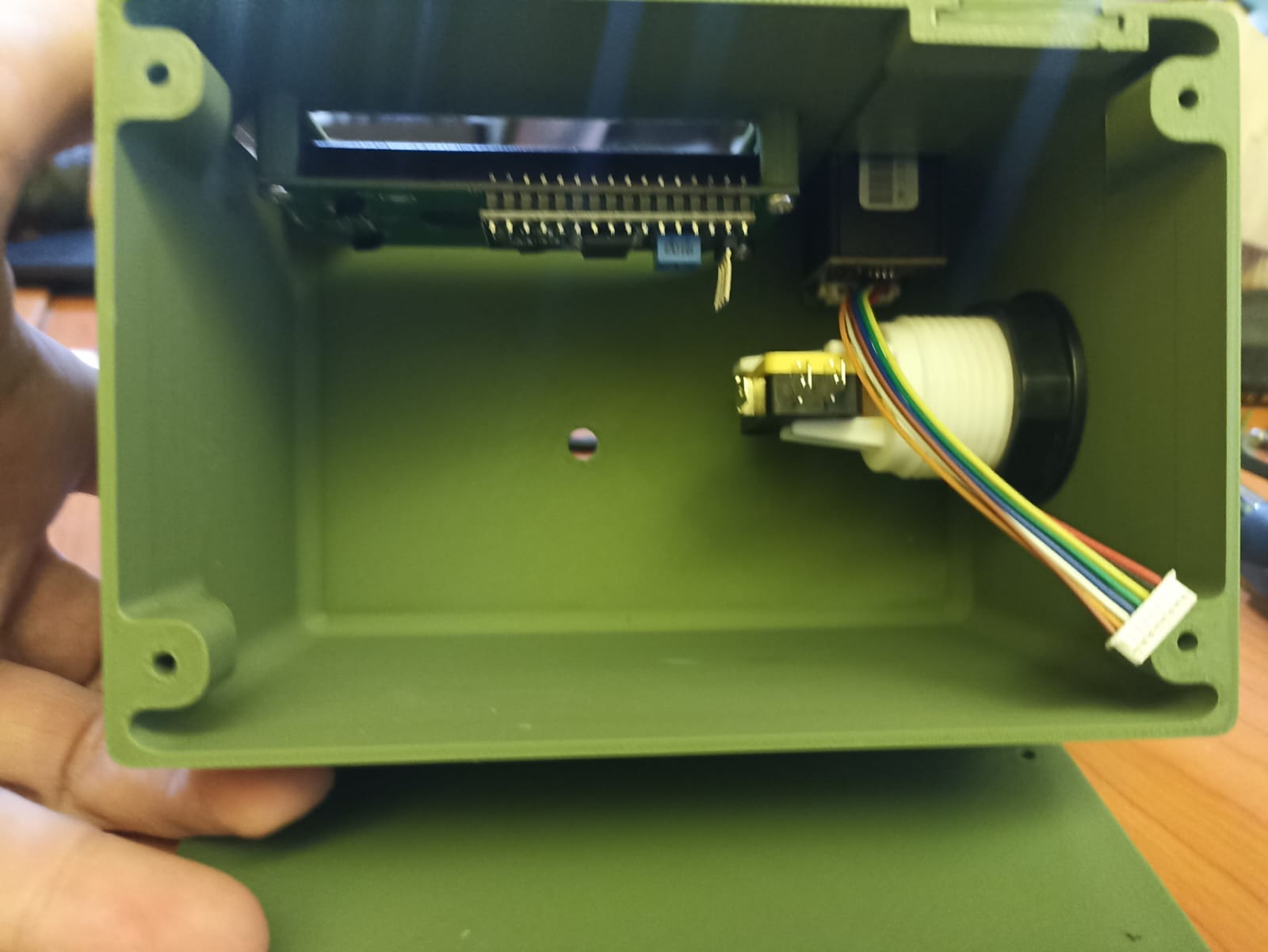
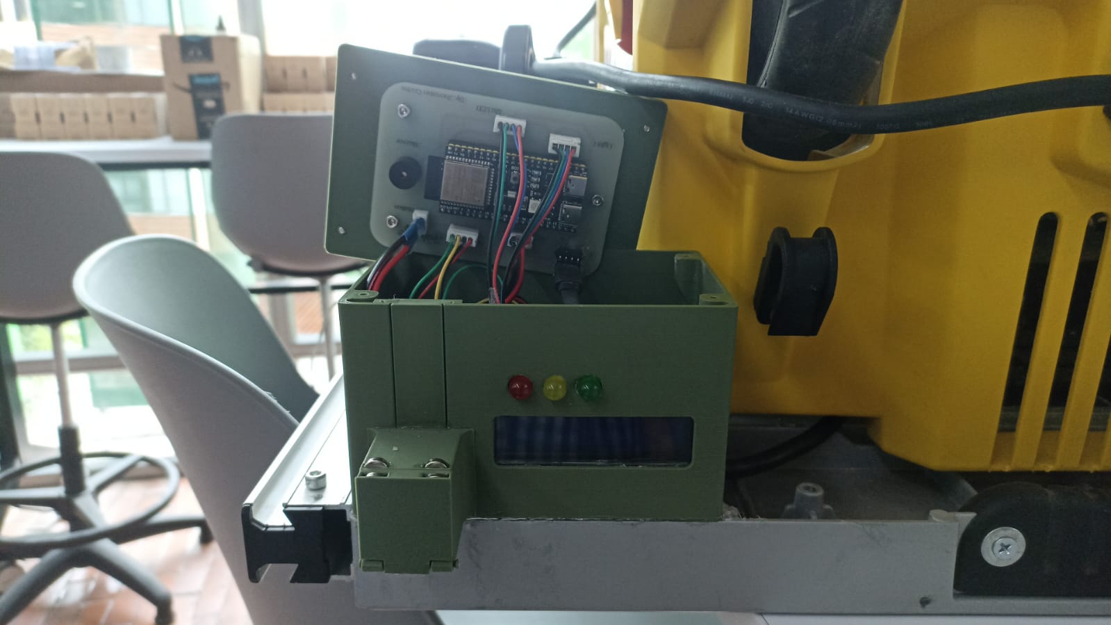
🔗 Phase 4: Integration & Testing
I wired all components inside my custom PLA enclosure. Each cable was crimped to match the headers on my single-sided PCB, which I milled on a Maker Carvera by removing all copper except the traces. Once connected, the system follows a strict flow to ensure safe operation:
4.1 System Flow
- Idle: Relay open → machine powerless. LCD shows “Waiting for user…”, all LEDs off.
- Authenticate: LCD prompts “Place Finger” (up to 5 attempts). The R307 sensor delivers >99% valid read rate (FAR <0.001%, FRR <1%).
- Grant access: On valid scan → relay closes (power enabled), green LED lights, LCD displays a 10-minute countdown in seconds (critical for user awareness).
- Failures: Each bad scan increments a counter. After 3 consecutive failures → relay remains open, red & yellow LEDs flash, buzzer sounds, LCD shows “Access Denied.”
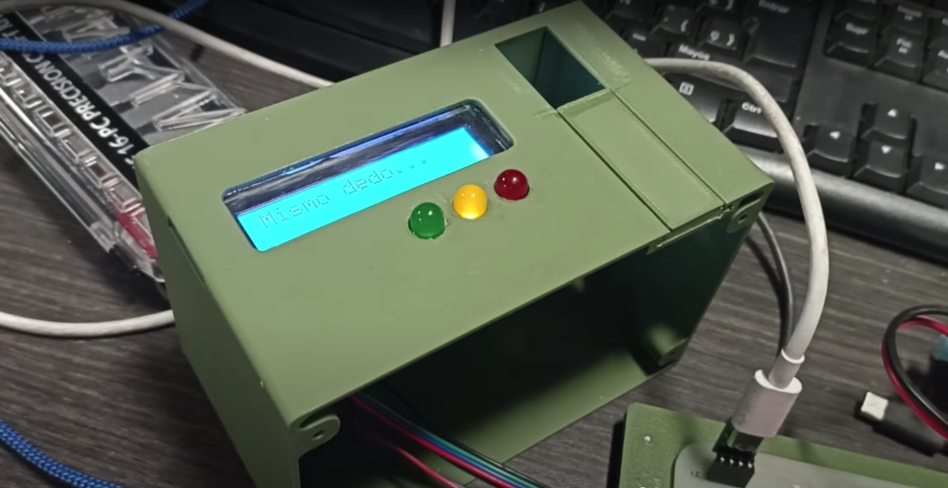
- Suspend mode: If 5 attempts elapse without unlock → low-power suspend (relay open, yellow LED steady, LCD “Standby – Press Emergency to Retry”). Pressing the emergency button resets the flow.
- Emergency stop: Pressing the emergency button at any time immediately opens relay, triggers buzzer, LCD “EMERGENCY LOCKOUT,” red LED on. After 30 s, normal startup resumes.
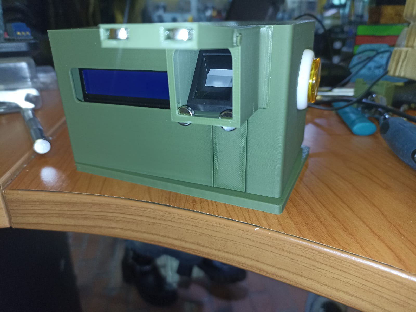
4.2 Assembly & Visuals
4.3 Step-by-Step Assembly
-
PCB Milling: I milled a single-sided PCB on the Maker
Carvera, carving away all unwanted copper to leave only the traces.
Single-sided PCB with milled traces -
Enclosure Printing: I 3D-printed the case in PLA,
test-fitted the PCB and filed openings for each component.
3D-printed PLA enclosure - Cable Crimping: I cut color-coded wires to length, stripped insulation, and crimped Dupont terminals.
- Module Mounting: I pressed the fingerprint sensor, emergency button, LCD, LEDs and buzzer into their slots until flush.
- Wiring: I routed cables through designated slots, secured them with zip-ties, and kept power and signal lines separated.
- PCB Installation: I placed the populated PCB in the case and fastened it with M3 screws and stand-offs.
- Final Connections: I plugged each connector onto its header, verifying orientation against silkscreen labels.
- Case Closure: I closed the lid carefully, ensured no wires were pinched, and tightened all screws.
- Bench Testing: I powered on the system, confirmed “Waiting for user…” on the LCD, tested valid/invalid scans and the emergency stop.
-
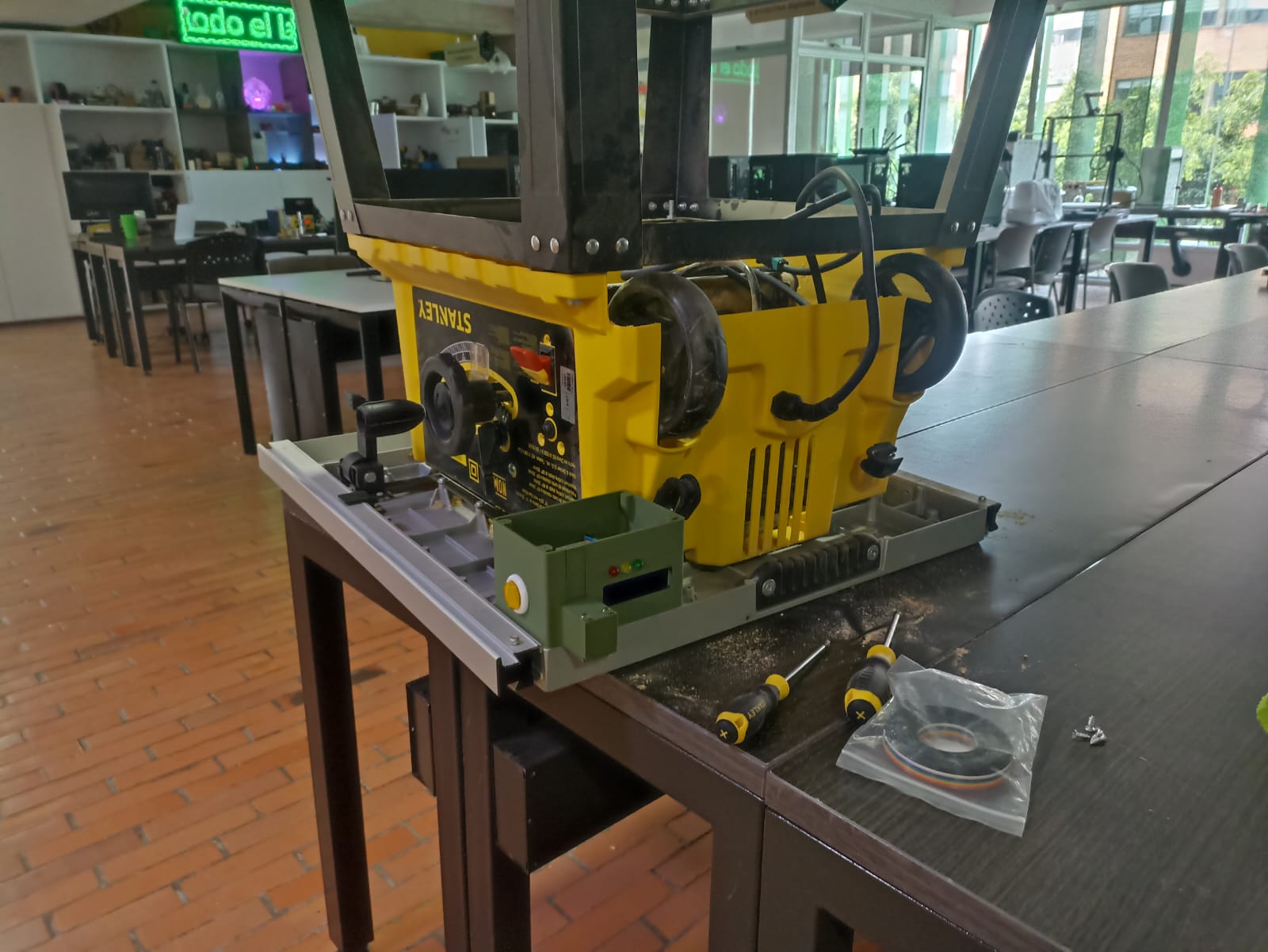
Machine Integration: I mounted the sealed case onto the
saw, connected the relay output to the saw’s power circuit, secured cables,
and performed a full operational test.
Final installation on the saw
4.4 Testing & Validation
As part of my Fab Academy evaluation, I conducted stress tests:
- ≈500 fingerprint scans over several hours → no false accepts, <1% false rejects.
- 50 emergency-stop activations → relay and buzzer responded within <10 ms each.
- Cooldown logic kept sensor temperature within safe limits throughout testing.
Pressing the emergency button instantly disables the relay, triggers a 30 s lockout, and lights the red LED. Unauthorized access activates buzzer + red LED and enforces a cooldown period before retry.
✅ Phase 5: Final Deployment & Validation
The final version was tested in the actual FabLab where the bench saw is located. A real session simulated a workshop environment:
- Unregistered users were denied access
- Registered fingerprints granted 10-minute machine control
- System safely locked and required reset via button after time expired
Everything was documented, including schematics, code, 3D files, and test logs. Final adjustments included mounting the system to a protective frame, polishing the acrylic display cover, and labeling ports.
💬 Feedback from Neil
Neil requested the exact reliability figures for our R307 fingerprint sensor module:
- False Acceptance Rate (FAR): < 0.001%
- False Rejection Rate (FRR): < 1.0%
This means the sensor rejects unauthorized prints with over 99.999% certainty and correctly recognizes valid prints over 99% of the time.
🔍 Final Conclusions
- Modular Design: Headers and custom cables make this system scalable and maintainable.
- Safety First: Cooldown logic and emergency overrides ensure no unsafe operation is possible.
- Admin/Operation Split: Makes management intuitive while keeping runtime logic lightweight.
- Real-World Proof: Tested successfully in a real FabLab with real tools and people.
- Future Upgrades: Ready for Telegram/MQTT integration, RTC logging, and improved interfaces.
This project shows how open-source tools and careful planning can lead to powerful safety systems built by students for real-world use.
FabSafe by Jhonatan Cortes is licensed under CC BY-NC-SA 4.0 International .
📦 Downloadable Project Files
🔌 Electronics
- 🧠 Fab Academy Circuit (.fzz) – Fritzing schematic for the full board
- 📦 PCB Fabrication Files (.zip) – Includes traces, outline and toolpaths
💻 Firmware & Code
- 🔐 admin_access.ino – Code for AP mode and fingerprint management
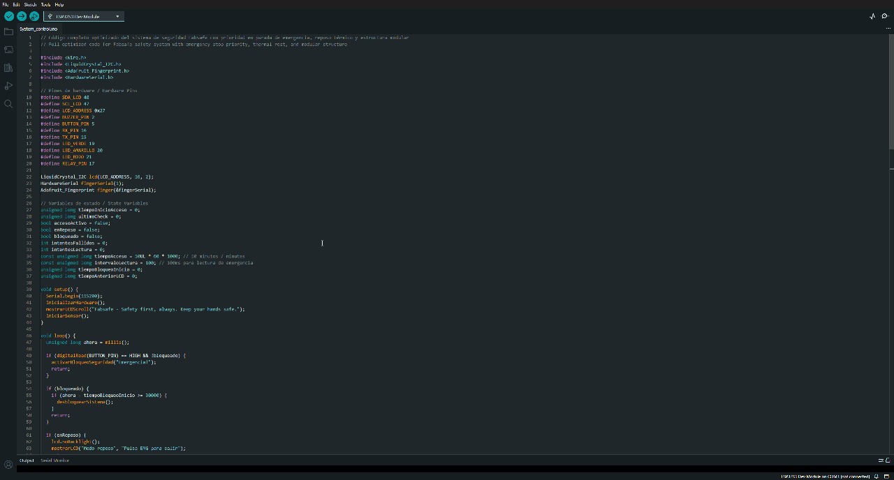
- 🧠 system_control.ino – Operational logic and main runtime code
📦 3D Design Files
- 🧩 Case_Final_Project.f3d – Fusion 360 parametric source file
- 🏗️ Enclosure Assembly (STL) – Full STL for reference
- 🔧 Top Cover (STL) – Separate STL for the lid
- 🧱 Small Top Piece (STL) – Optional small section cover
- 🖐️ Fingerprint Mount (STL) – Holder for fingerprint sensor
- 📏 Locking Slide (STL) – Slide mechanism for sensor lid
🔦 Laser Cutting Files
- 📐 Cortelaser.DXF – DXF for laser-cut acrylic display shield
- 🖼️ FP_v1.svg – Vector version of panel
- 📐 FP_v1.dxf – DXF panel version for compatibility
- 📎 Cortelaser.SLDPRT – SolidWorks file of acrylic part