Assignments
Group Assignment:
- Complete your lab’s safety training.
- Test runout, alignment, fixturing, speeds, feeds, materials and toolpaths for your
machine.
- Document your work to the group work page and reflect on your individual page what
you learned.
Individual Project:
- Make (design+mill+assemble) something big.
Week 7. Computer-Controlled Machining
Reflection on Group Work and Safety Training
This week, our group engaged in several activities starting with a comprehensive safety training session led by our teammate Evelyn from Peru. She provided clear guidelines about essential safety standards within Fab Labs, including general procedures, PPE, and common risks. This was especially useful for us at the ENA University FabLab, since our space is relatively new and still improving its internal processes.
Thanks to that session, I was able to identify areas where we could improve our own lab’s safety protocols. I even arranged a meeting with our university team to begin implementing new safety measures and awareness strategies.
As part of our group exploration, we worked with a large-format CNC machine. Due to its size and power, I initially found it intimidating, but after several days of practice I became more comfortable. We learned how to power it on safely, run basic calibration, and identify crucial steps like origin setting, material Z-height, tool types, and machine tolerances. We also explored different types of cuts and operations it allows — including roughing, pocketing, and contouring — as part of our group task.
Introduction
For my individual assignment, I didn’t want to make a large object “just for the sake of size.” Instead, I began by analyzing which item in our FabLab could benefit from a better workspace.
I identified a common issue: our small vinyl cutter had no fixed station and was frequently moved around. This inspired me to design a custom table with integrated storage that could safely house the cutter, provide workspace, and support proper cable management.
The following sections describe the full development process — from defining goals and design criteria, to preparing toolpaths and executing the job on the CNC machine, and finally assembling and testing the final piece.
1️⃣ Project Idea & Objectives
At the beginning of this assignment, I didn’t want to build a large object just to meet the size requirement. Instead, I reflected on what could be useful in our lab. We have a Cricut Maker 3 vinyl cutting machine, but no dedicated station or workspace for it — it's often moved around without a stable setup.
After searching for inspiration, I found a design on Pinterest that finally caught my attention. It was simple, functional, and included storage — exactly what I envisioned.
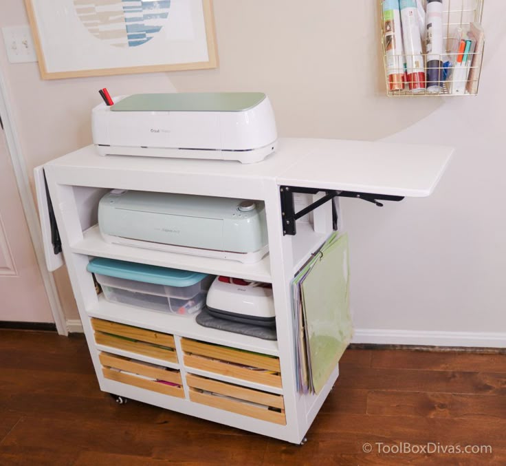
Image 1 – Inspiration found on Pinterest
Of course, I couldn’t copy that exact design. CNC routing has different constraints compared to traditional furniture making. That’s why I started by considering how each part would be assembled using tabbed joints and pockets, and how material thickness would influence the fit.
I then made a rough sketch to structure the idea and later used an AI tool to generate a more polished visual that better represents the final intention for the CNC-friendly design.
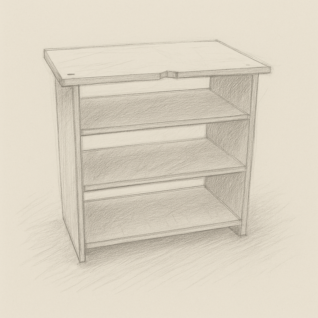
Image 2 – Concept sketch enhanced with AI for clarity and presentation
2️⃣ Design Process
For this furniture project, I chose to work directly in 3D modeling using Fusion 360, and later unfold and flatten the parts for CNC machining. This is a workflow I commonly use — even in laser cutting — because it allows me to confirm dimensions, ensure all parts align properly, and anticipate the physical fit before generating toolpaths. In this case, my goal was to create a custom table for a machine that didn’t yet have a fixed location.
I started by defining the physical constraints of the space where the furniture would be placed. After measuring the available area, I determined the structure should be no more than 92 cm tall, 65 cm deep, and 100 cm wide. These values would become my fixed design limits.
📏 Key Measurements
- Total Height: 92 cm
- Depth: 65 cm
- Width: 100 cm
- Material Thickness: 18 mm plywood (triplex)
Before jumping into CAD software, I always begin with traditional methods. I made a hand-drawn sketch of the full structure, including proportions and notes about the function and location of each piece. This helped me visualize the overall form and pre-plan where joints and connections would be placed.
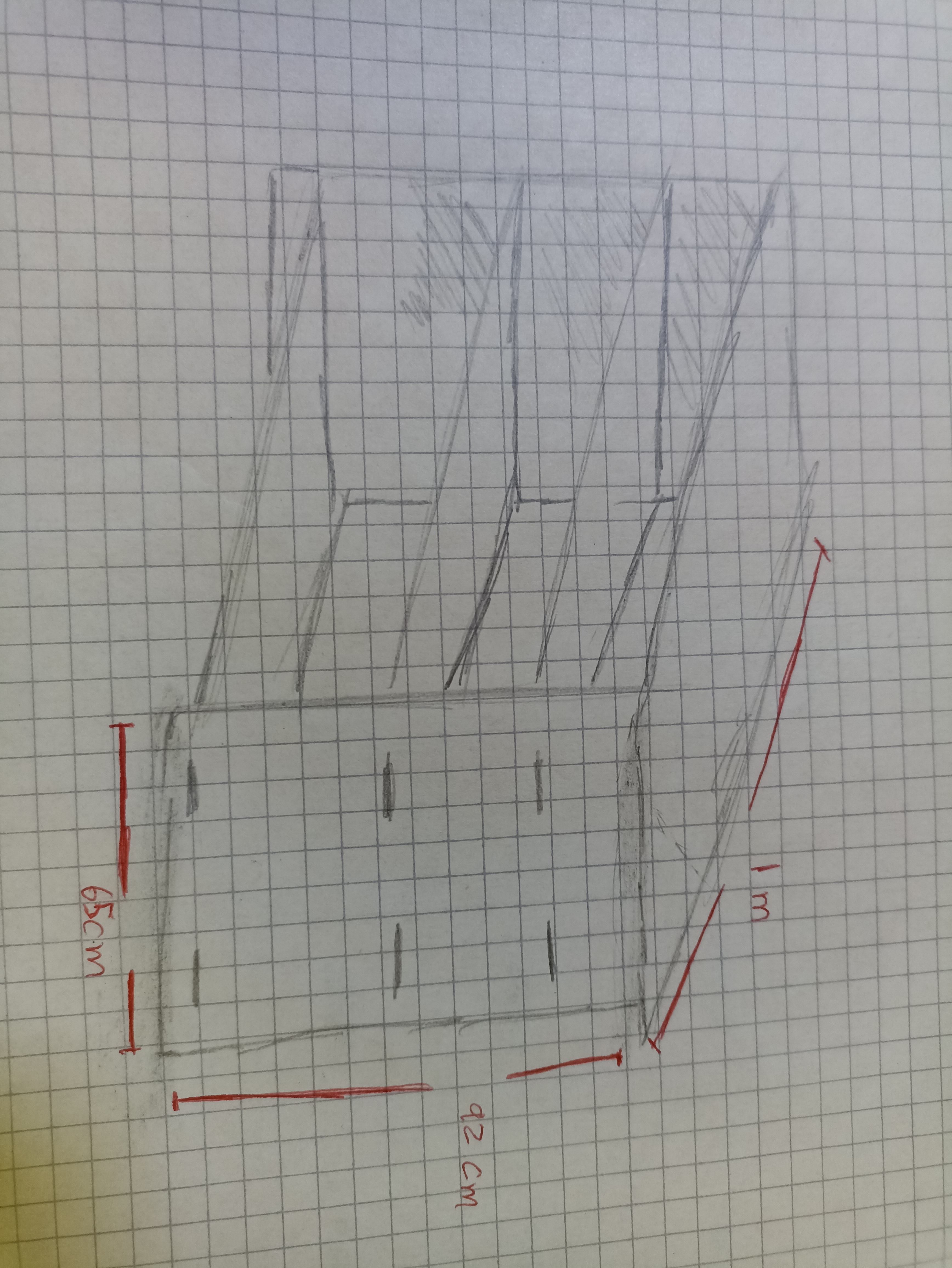
Image – Hand-drawn sketch showing full furniture idea with annotations
Then I moved into Fusion 360. I began with 2D sketches of the most important elements. First, I drew the side panels. These define the height and shape of the piece. I added curves for aesthetics and included holes for horizontal pieces.
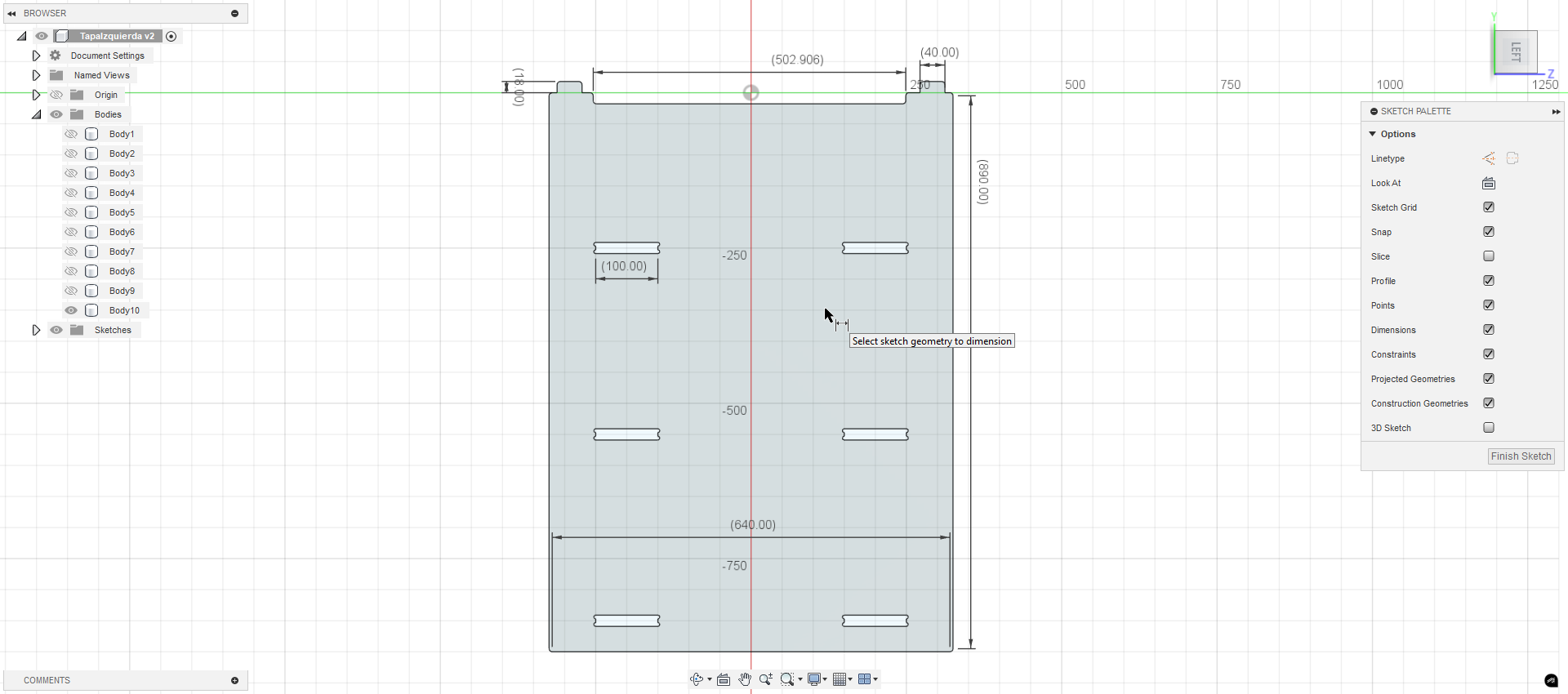
Image – First sketch in CAD showing lateral profile
I extruded this 2D profile to 18 mm, matching the real thickness of the plywood, and turned it into a solid body. Using the mirror tool, I duplicated it across the center plane, creating a symmetric structure that would define the furniture's width.
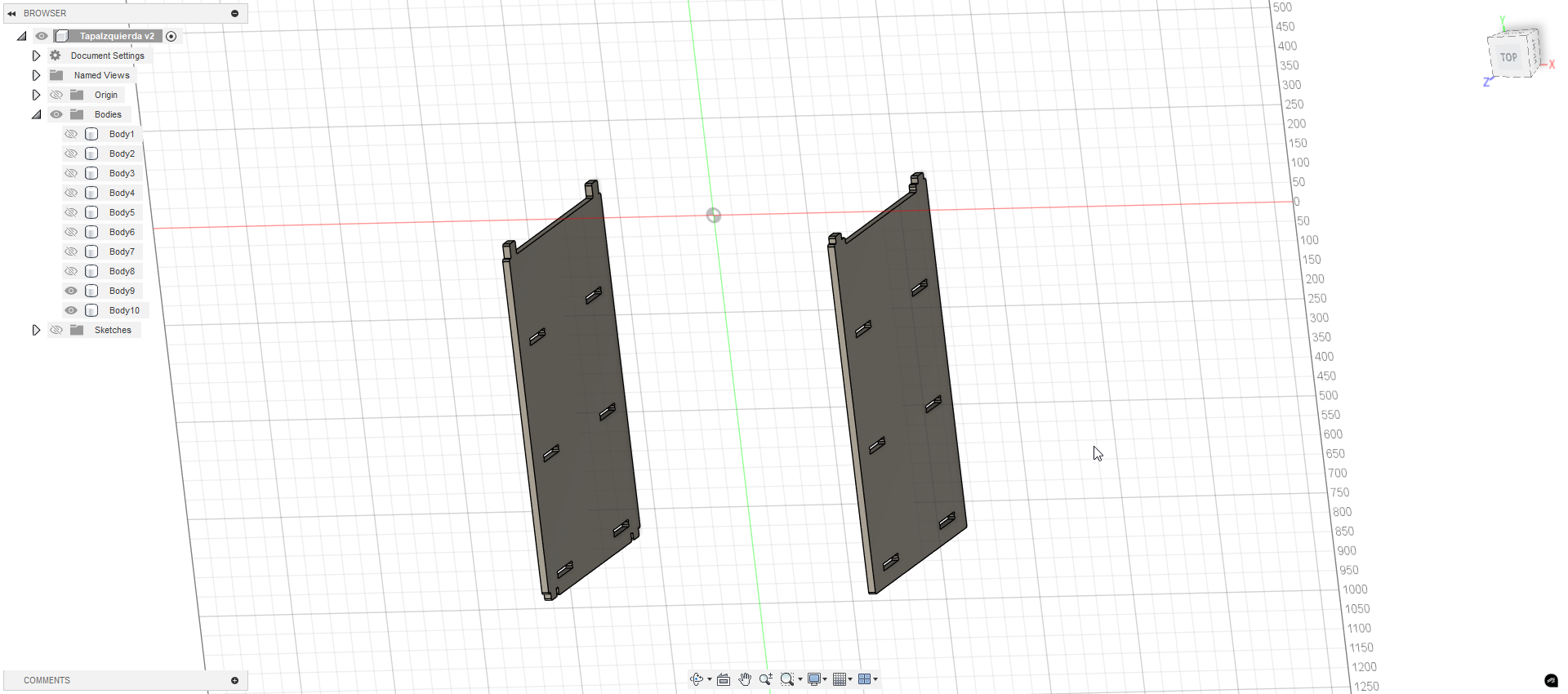
Image – 3D model of one side panel duplicated for full frame
The next step was to add horizontal braces. These would connect the two lateral panels and provide support. I started with a single 2D sketch of one brace and extruded it to the correct thickness.
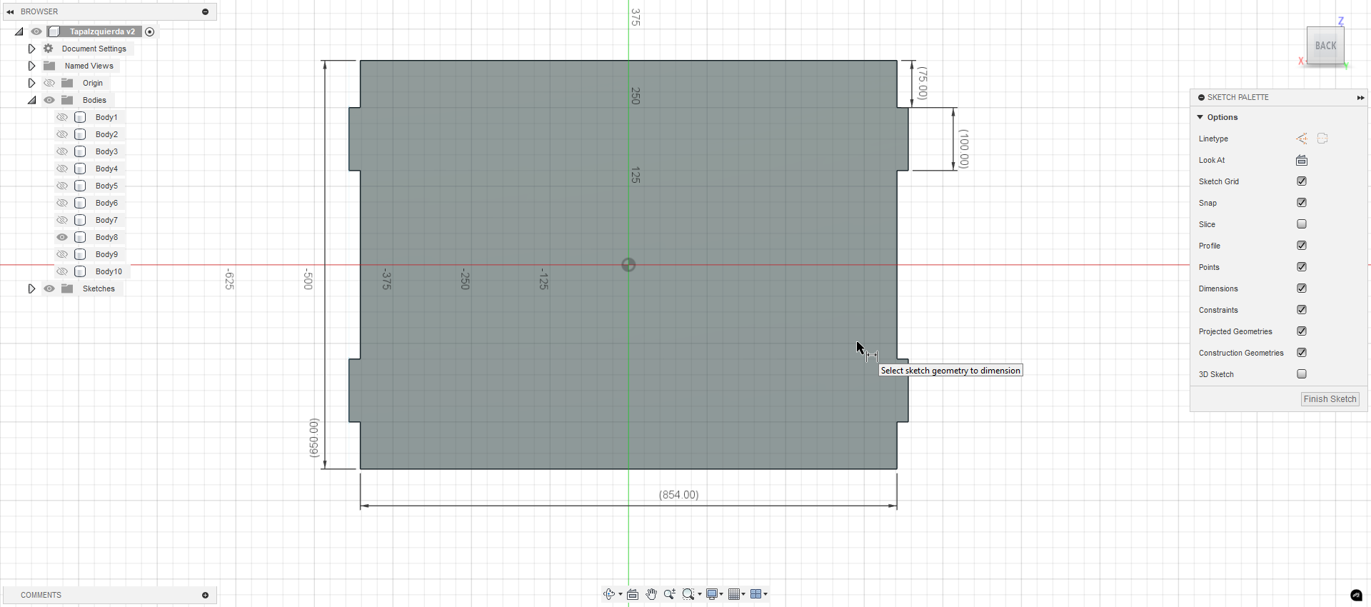
Image – Sketch of horizontal brace (travesaño)
After validating its fit, I placed three copies into the design: one at the base, one near the middle, and one towards the top, forming the internal shelf structure and reinforcing the rigidity of the piece.
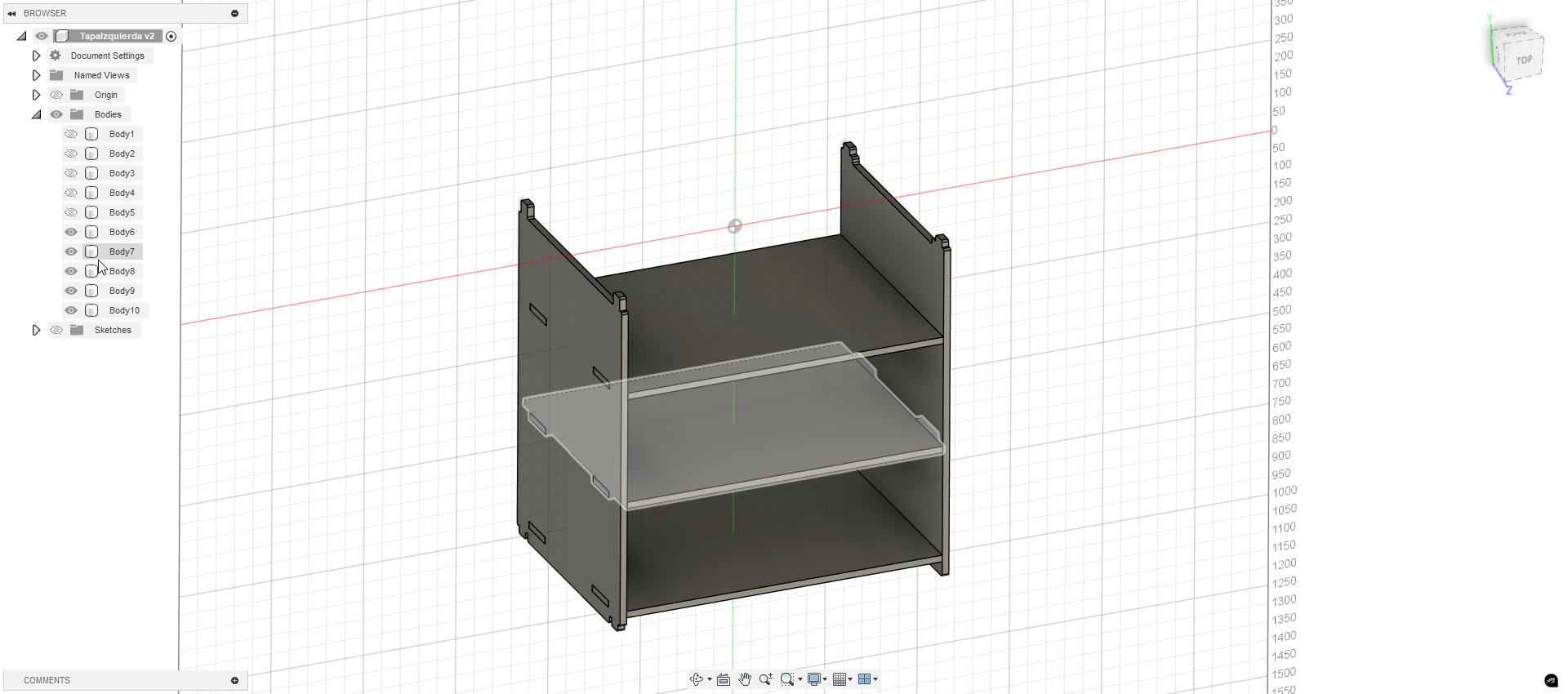
Image – All three horizontal braces in place
With the base complete, I moved on to the top surface. I drew it in 2D, then added cutouts to ensure it would fit snugly on the tabs of the side panels. These cutouts were dimensioned precisely based on the real material thickness.
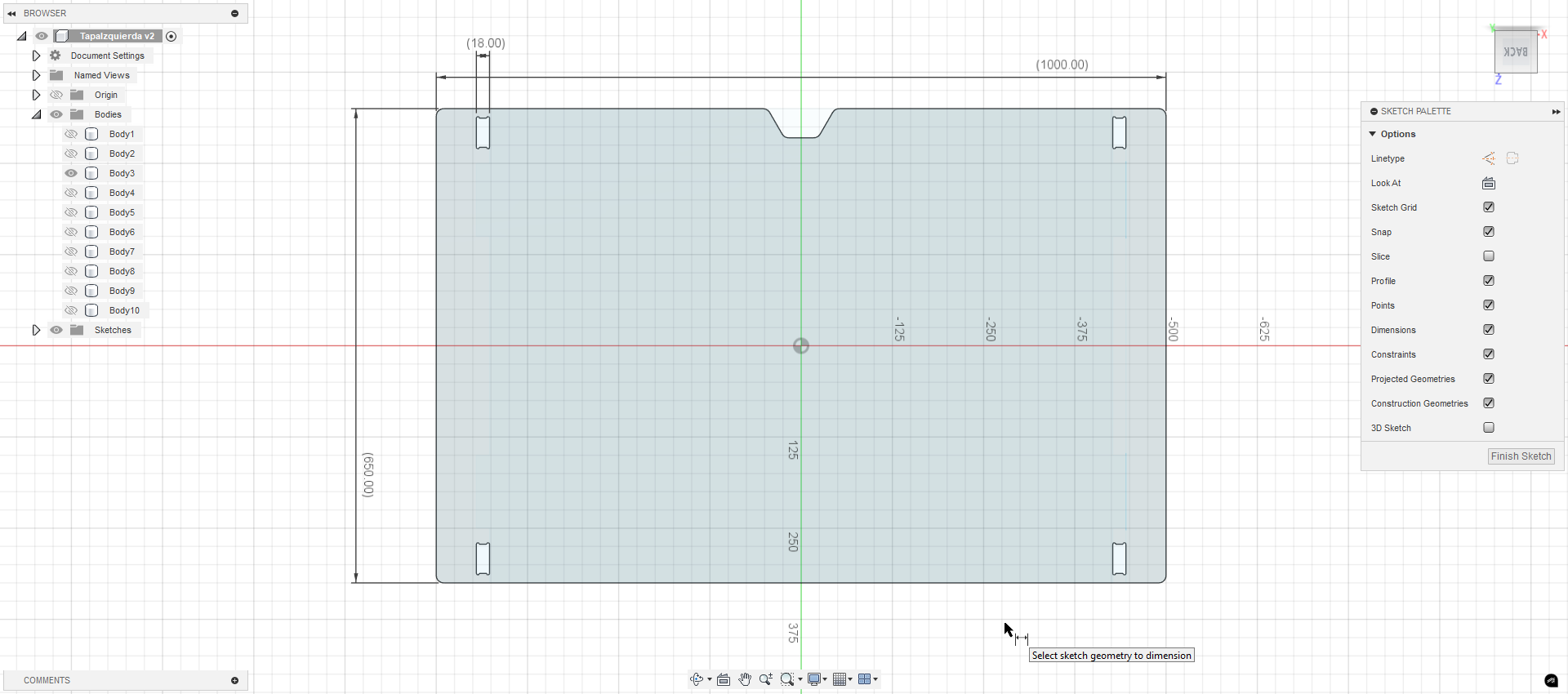
Image – Top panel sketch in 2D
To ensure proper fitting during CNC cutting, I added dogbone fillets to all internal square corners of the joints. These small arcs are necessary because the CNC uses a round endmill and cannot make perfect right-angle internal corners.
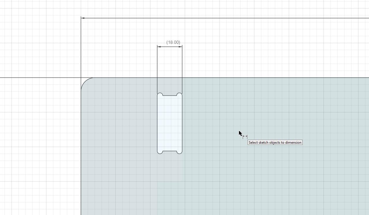
Image – Dogbone-style fillets added to inner joints
After assembling all components virtually, I placed the top panel and confirmed alignment and fit with the rest of the structure. This step helped me identify any potential interference or adjustment before moving to fabrication.
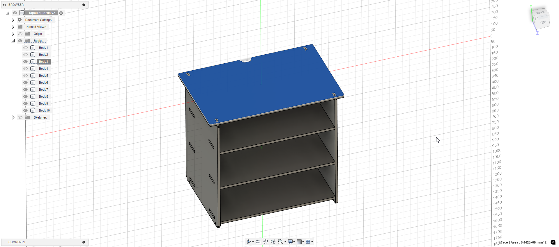
Image – Top panel added, completing the furniture structure
As part of the testing process, I validated my tab design by physically assembling test pieces. I discovered that with my chosen tool and material, using 0 mm tolerance (no offset) was enough to produce tight-fitting joints. The parts locked together with pressure and didn’t require glue, which improves both simplicity and strength.
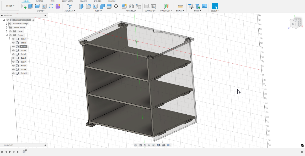
Image 3 – CNC test pieces fitted with no tolerance (tight press-fit)
The material selected for this build is 18mm plywood (triplex). I chose it because the final furniture will be placed in an operational area of the lab, where it will undergo frequent use and may need to support heavy loads. I’ve also worked with this material in past projects, so I’m familiar with its behavior under CNC conditions.
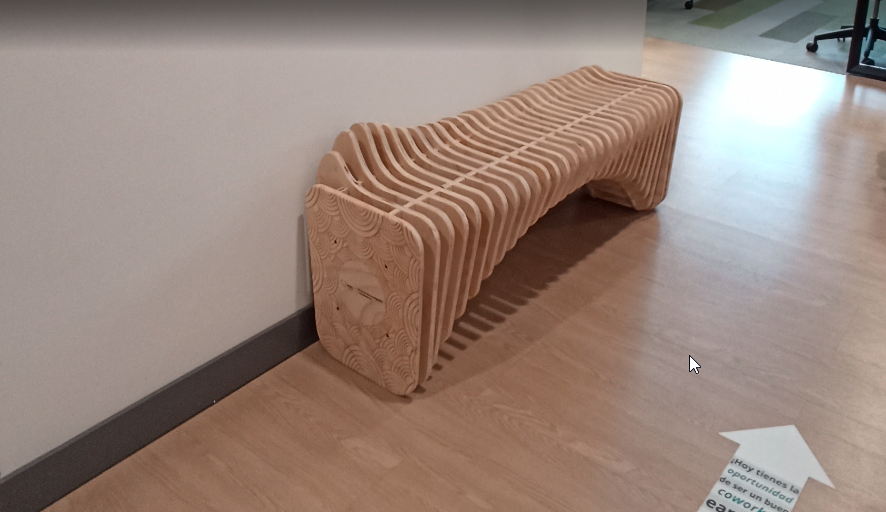
Image 4 – Previous furniture made with the same material
Once I finalized the 3D model, I exploded and arranged the parts within Fusion 360 to prepare them for the CAM workflow. This allows a direct transition from design to toolpath generation, while maintaining dimension accuracy and nesting efficiency.

Image 5 – Final 3D model of the furniture design
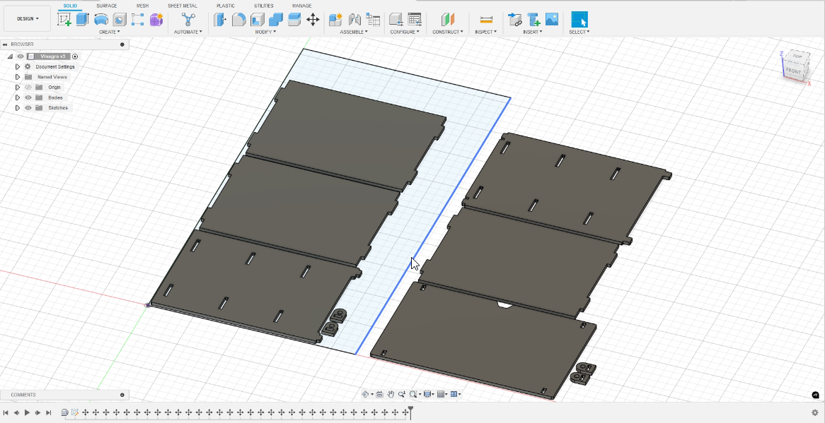
Image 6 – Flattened layout of parts ready for CAM processing
3️⃣ CAM Setup & Toolpaths
I started by defining my material in Fusion 360. In the Setup tab,
I chose Fixed Size Box and entered the real dimensions of my
plywood: 1130 mm width (X), 2300 mm depth (Y), and 18 mm thickness (Z). I set an
8 mm offset on X and Y, and 0 mm on Z so the tool will cut exactly through the
sheet.
This tells the CAM engine the exact size and position of my stock before
creating any toolpaths.
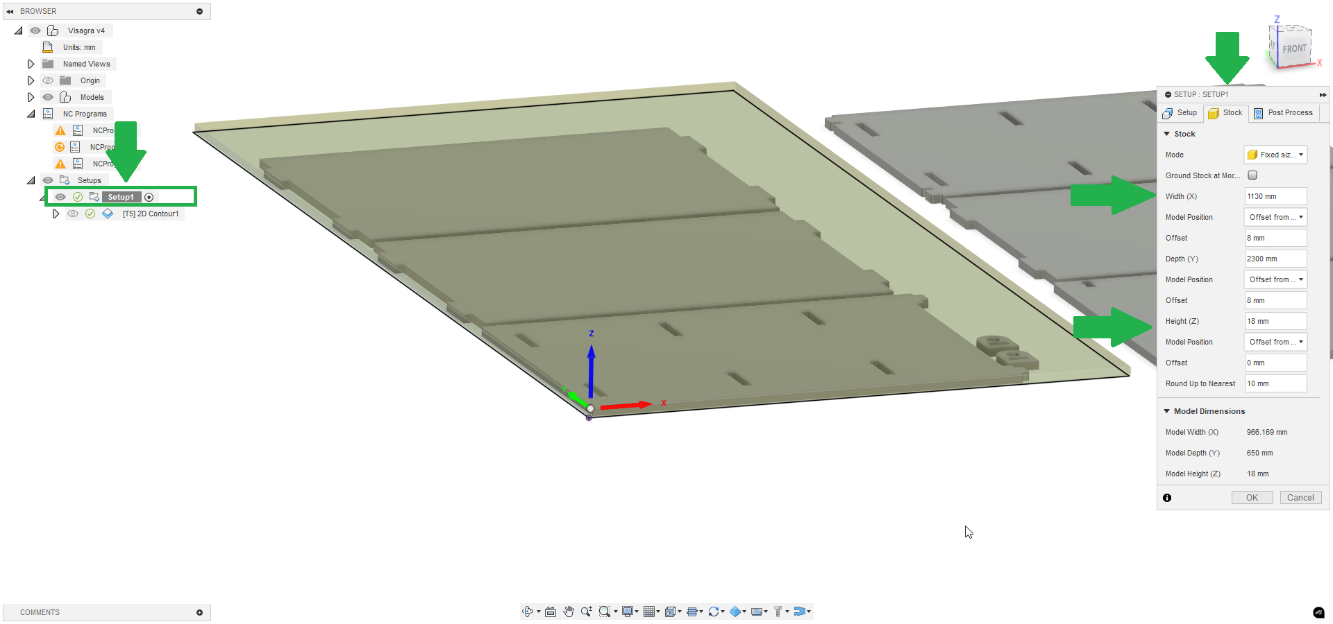
Image S – Stock Setup panel: size 1130×2300×18 mm with 8 mm X/Y offsets
Next, I arranged all the parts on the stock inside the same Setup tab. I dragged
each shape into position to optimize material use and avoid waste.
This ensures the CNC only cuts where I want and maximizes wood yield.
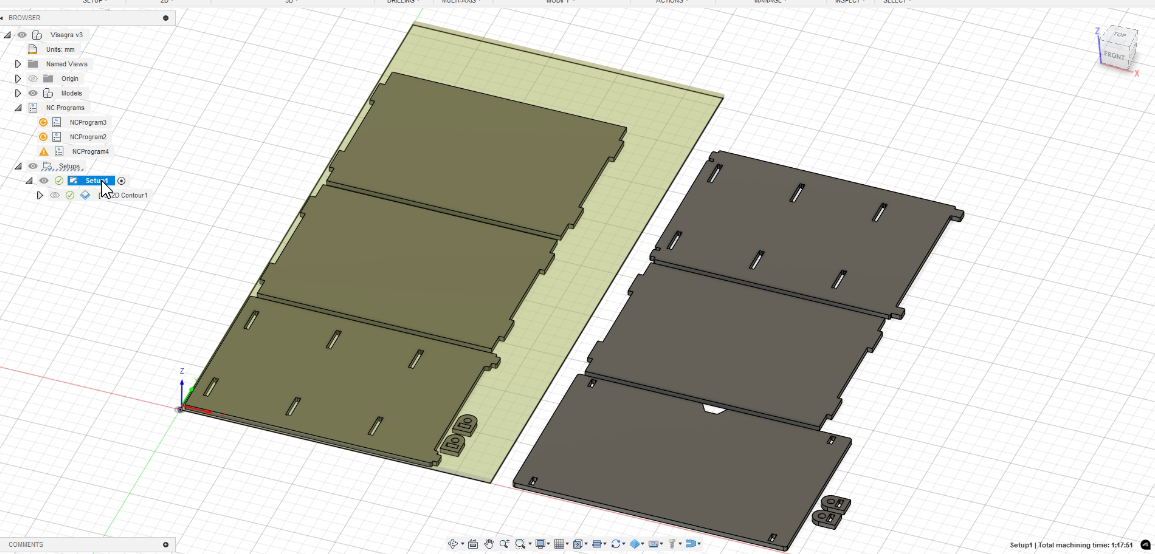
Image 7 – Parts positioned on the defined stock
For clean-through cutting of 18 mm plywood, I chose a 6.35 mm (1/4") carbide
compression end mill with 2 flutes. This tool pushes fibers downward on
entry and upward on exit, leaving smooth edges on both faces and minimizing
tear-out.
Compression bits are ideal for through-cuts where edge quality matters on both
sides.
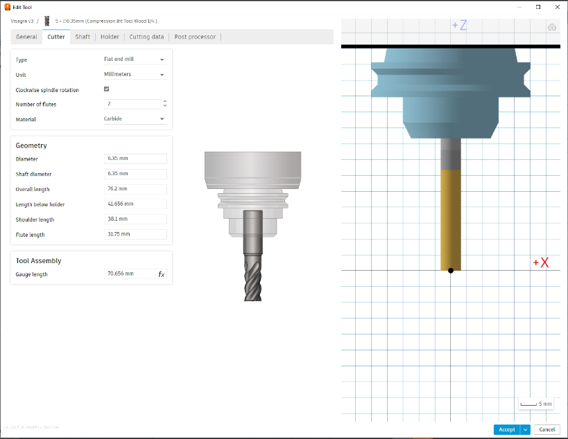
Image 8 – 6.35 mm carbide compression bit for dual-face finish
| Attribute | Value | Purpose |
|---|---|---|
| Diameter | 6.35 mm (1/4") | Matches material thickness for stability |
| Flutes | 2 | Good chip evacuation + finish |
| Type | Compression | Clean edges on both faces |
| Material | Carbide | High hardness, long tool life |
| Flute length | 31.75 mm | Complete engagement through stock |
I selected the 2D Contour operation in Fusion 360 to follow each
part’s outline. Contour keeps the bit at a constant Z-height along the profile.
Ideal for clean profile cuts around shapes.
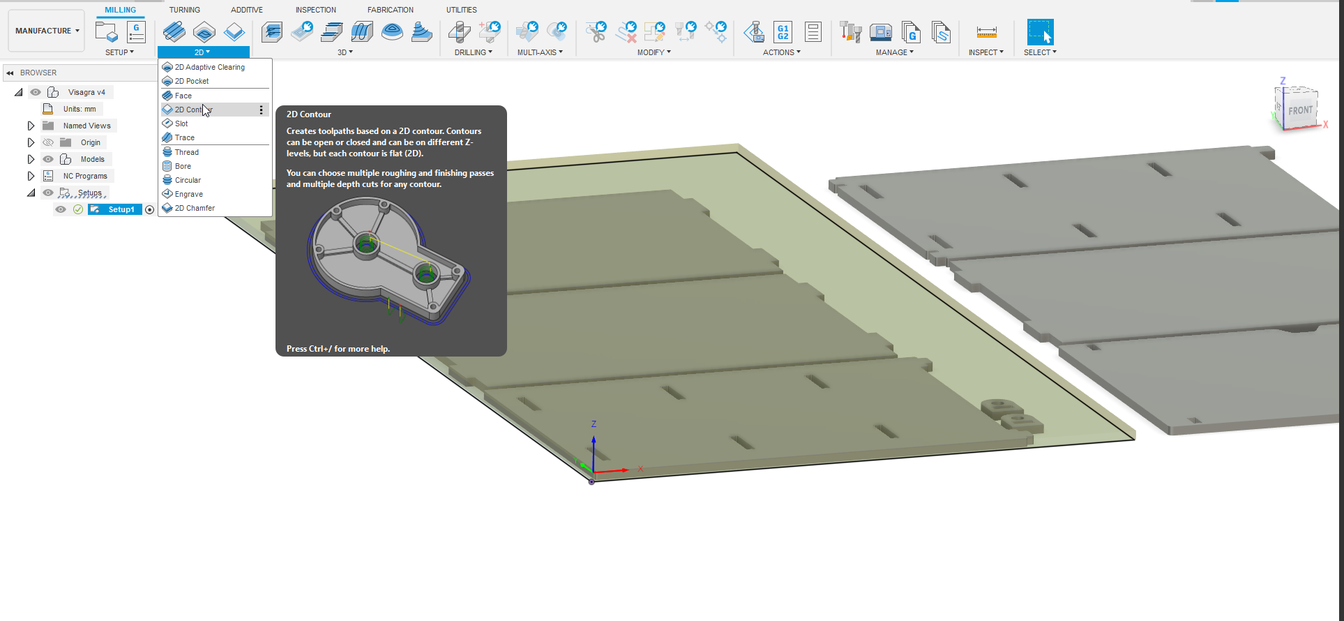
Image O – 2D Contour operation selected
To prevent wood tear-out when plunging, I enabled Ramp Entry under
Linking > Ramp. I set a 4° ramp angle, 4.5 mm max ramp step, and 1.6 mm
clearance height, allowing the bit to enter gradually.
Gradual entry reduces tool stress and material damage.
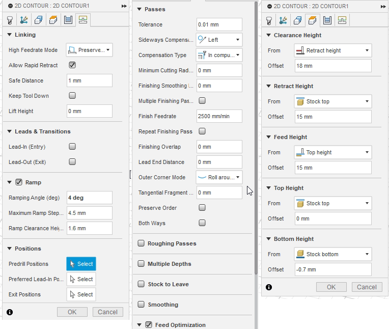
Image P – Parameters panel: feed, speeds, ramp settings, heights, tolerance
Below is a preview of the actual toolpaths in Fusion 360, showing the contour lines
and ramp entries. The yellow lines represent rapid moves, and the red lines show the
cutting passes.
This gives a clear view of how the machine will move.
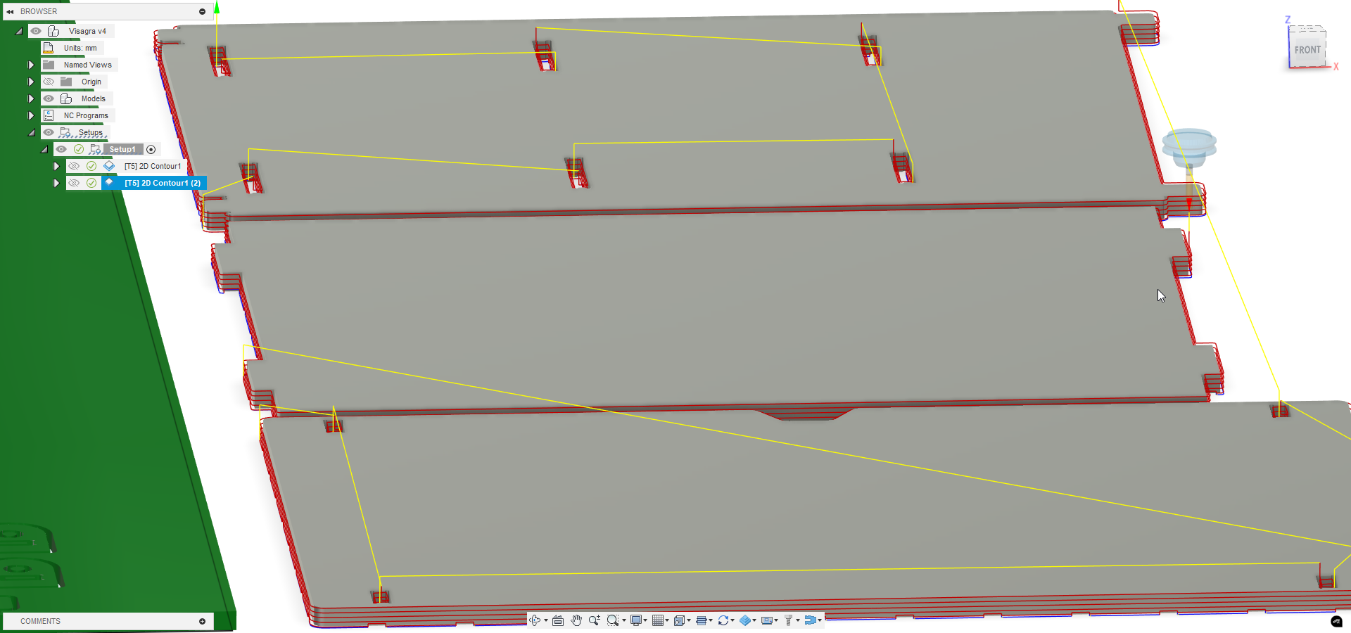
Image T – Toolpath preview: yellow rapids and red cutting passes
🔎 Detailed Toolpath Parameters
These settings were fine-tuned from group tests to balance speed, finish, and tool life:
| Parameter | Value |
|---|---|
| Spindle speed | 18 000 rpm |
| Cutting feed rate | 1 500 mm/min |
| Plunge feed rate | 600 mm/min |
| Depth per pass | 18 mm (full thickness) |
| Ramp angle | 4° |
| Max ramp step | 4.5 mm |
| Ramp clearance height | 1.6 mm |
| Retract height | 15 mm above stock top |
| Feed height | 15 mm above stock top |
| Top height | 0 mm (stock top) |
| Bottom height | -0.7 mm (below stock bottom) |
| Tolerance | 0.01 mm |
| Sideways compensation | Left |
| Feed optimization | Preserve order |
| Tab size & spacing | 10 mm × 3.5 mm every 80 mm |
I carefully added tabs (10 × 3.5 mm) every 80 mm along each contour to hold parts
securely until completion.
Tabs prevent premature part release and potential damage.
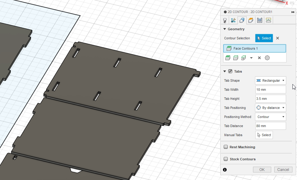
Image 10 – Tabs placed at 80 mm intervals
Finally, I ran a full simulation to verify there were no collisions and the tool followed the intended path cleanly within material boundaries.
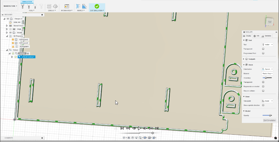
Image 11 – Final simulation shows clean toolpath with no collisions
Video – CNC toolpath simulation demonstrating full operation
4️⃣ Machining Process
Before operating our CNC machine, we follow a precise startup protocol to ensure safety and proper machine performance:
- 1️⃣ Open the air valve to activate the pneumatic system (kept off to preserve the compressor).
- 2️⃣ Press the oil pump button to automatically lubricate the system before any movement.
- 3️⃣ Power on the control module.
- 4️⃣ Unlock the emergency stop, which remains engaged by default after shutdown.
- 5️⃣ Turn the energy key to enable power to the drivers.
- 6️⃣ Switch on the stepper drivers.
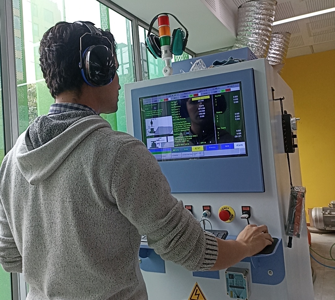
Image 12 – CNC control panel interface
With the machine initialized, the first step is performing a homing sequence so that the machine locates the zero point for all axes (X, Y, Z).
Next, we prepare the sacrificial layer — in this case, a 4 mm MDF board — placed under the workpiece to allow clean-through cuts without risking damage to the machine’s bed.
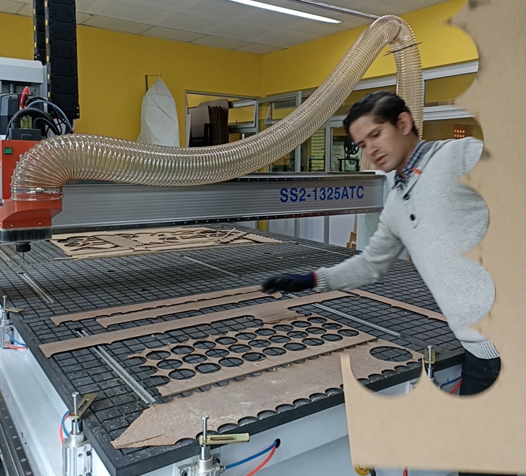
Image 13 – Installing the 4mm sacrificial MDF board
The actual workpiece is then mounted on top. Due to its size and weight, this step is done carefully, using gloves and with at least two or three people.
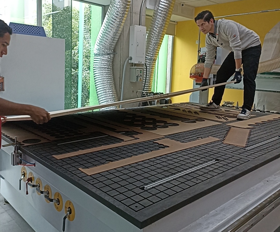
Image 14 – First step of material mounting
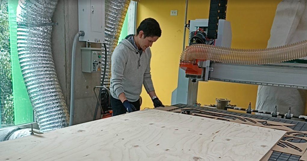
Image 15 – Final positioning of the plywood board
With the material fixed, we use the handheld control to gently move the machine and define the XY origin point (usually at the lower-left corner). After that, we lower the tool to set the Z height using the touch probe — even if using a single tool, this step is critical to ensure accurate depth.
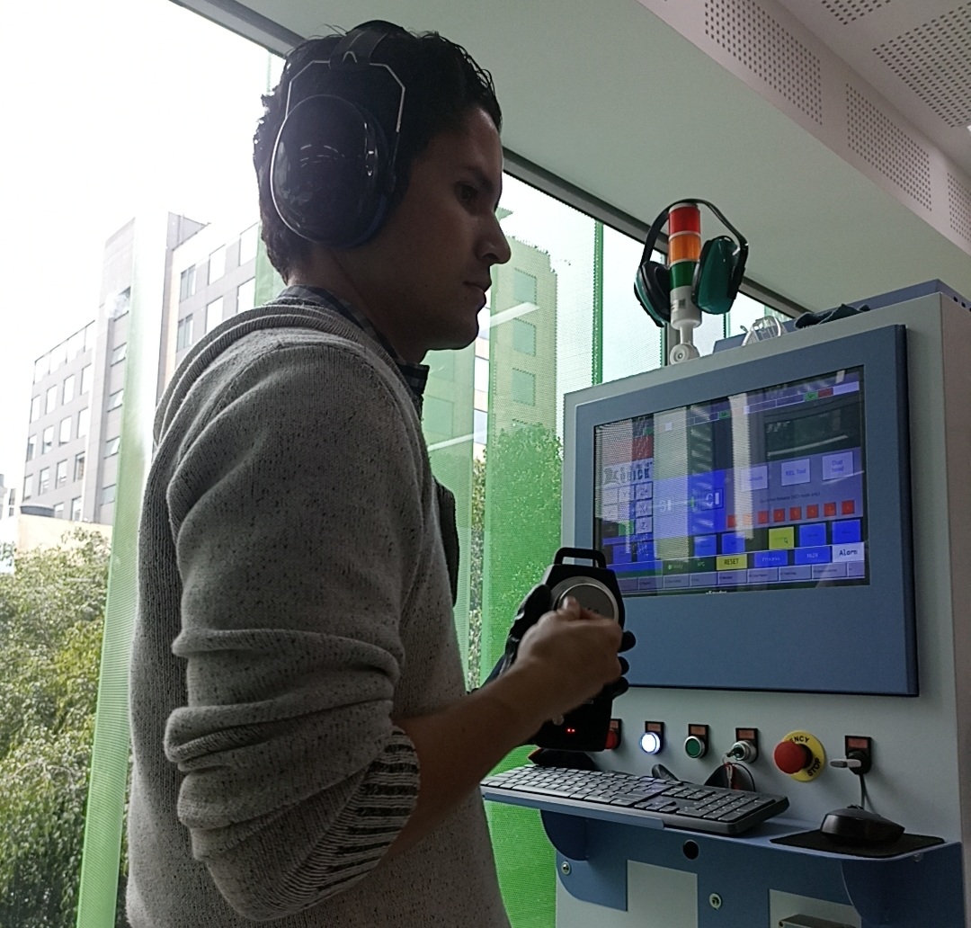
Image 16 – Operator using the control to set XY origin
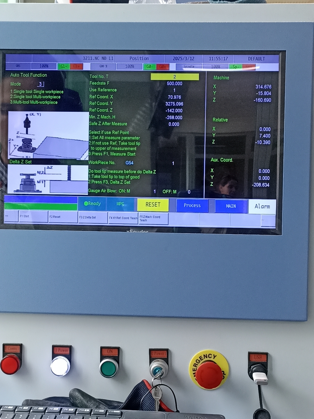
Image 17 – Z-axis height calibration using the touch probe
Once everything is set, we transfer the prepared CAM file to the machine and begin the cutting process. The ramp entry, feedrates, and tab configuration ensure a smooth and safe operation.
Video – Starting the CNC cutting process
After all the pieces are cut, we wait for the machine to finish, then proceed with careful removal and tab cutting. At this point, the parts are ready for sanding and final assembly.
Video – CNC finishing the final part of the job
5️⃣ Assembly & Finishing
After machining all the parts, the first step was to remove the tabs cleanly. For this, I used a compact handheld multi-tool that acts as a fine jigsaw. It allowed me to cut the tabs precisely without damaging the surrounding surface.
Once the tabs were removed, I lightly sanded the tab areas to remove sharp edges. Fortunately, the compression bit I used left very clean cuts — with no burning and almost no burrs.
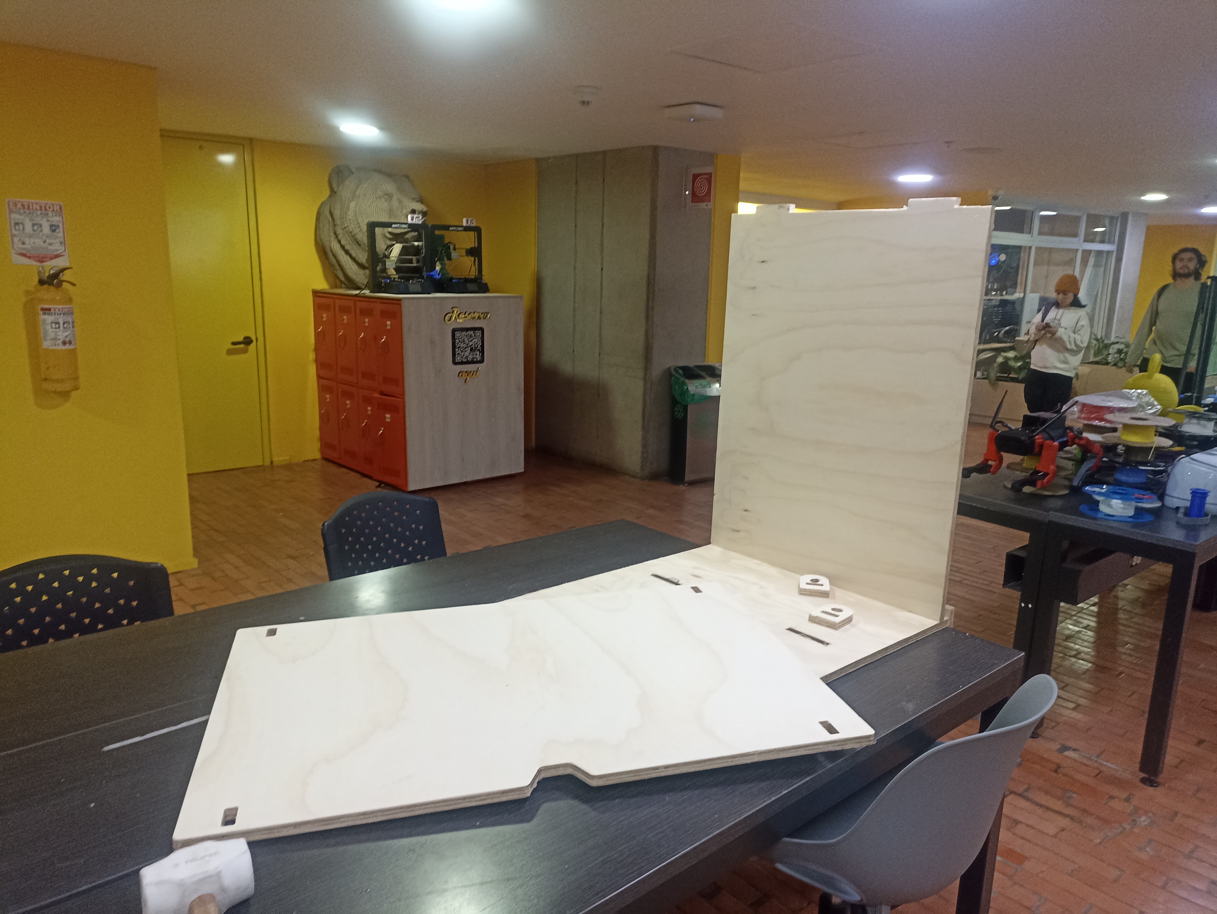
Image 18 – First pieces after removing tabs and light sanding
The next step was the assembly process. Using a rubber mallet, I started by joining one of the side panels with the base, carefully aligning all joints. Then I inserted the internal shelves and continued with the second side panel. Finally, I added the top surface which locks all the parts in place with a strong press-fit.
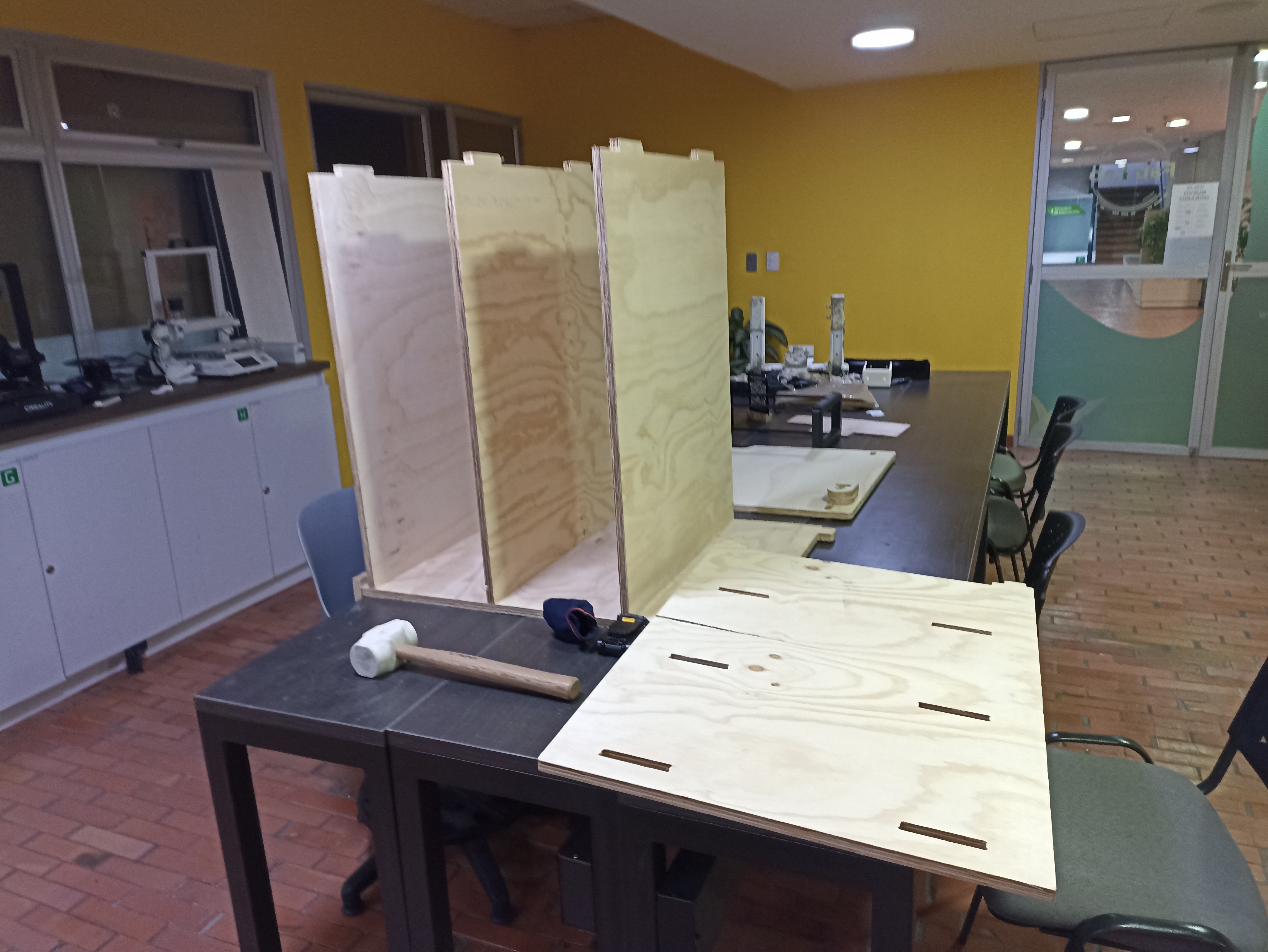
Image 19 – Mid-assembly: shelves and one side panel in place
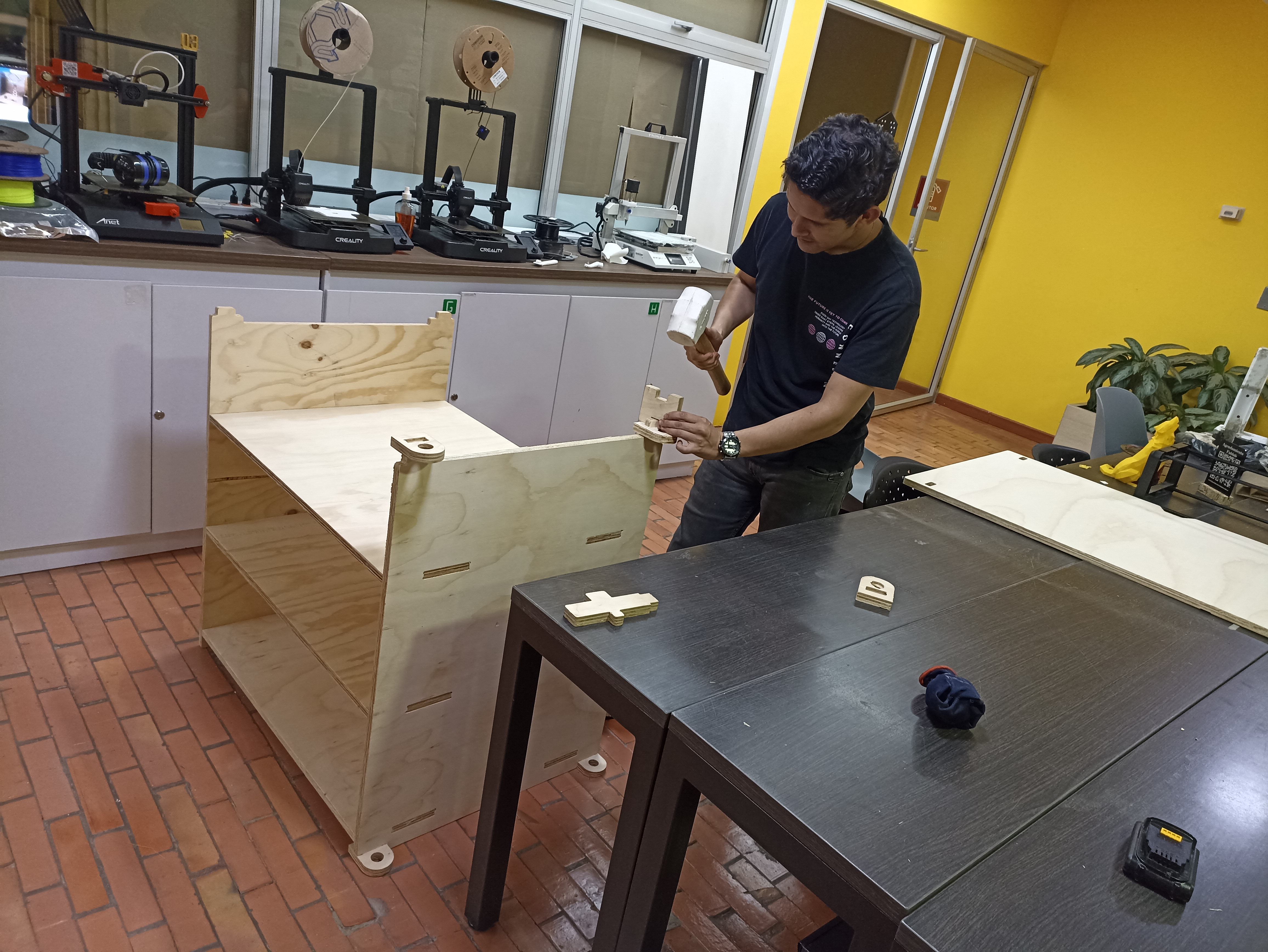
Image 20 – Final adjustments using a rubber mallet for press-fit
Once fully assembled, I checked for fit and structural rigidity. There were no loose joints, and the piece felt very stable. All components aligned properly, and the joints held firmly without the need for screws or glue.
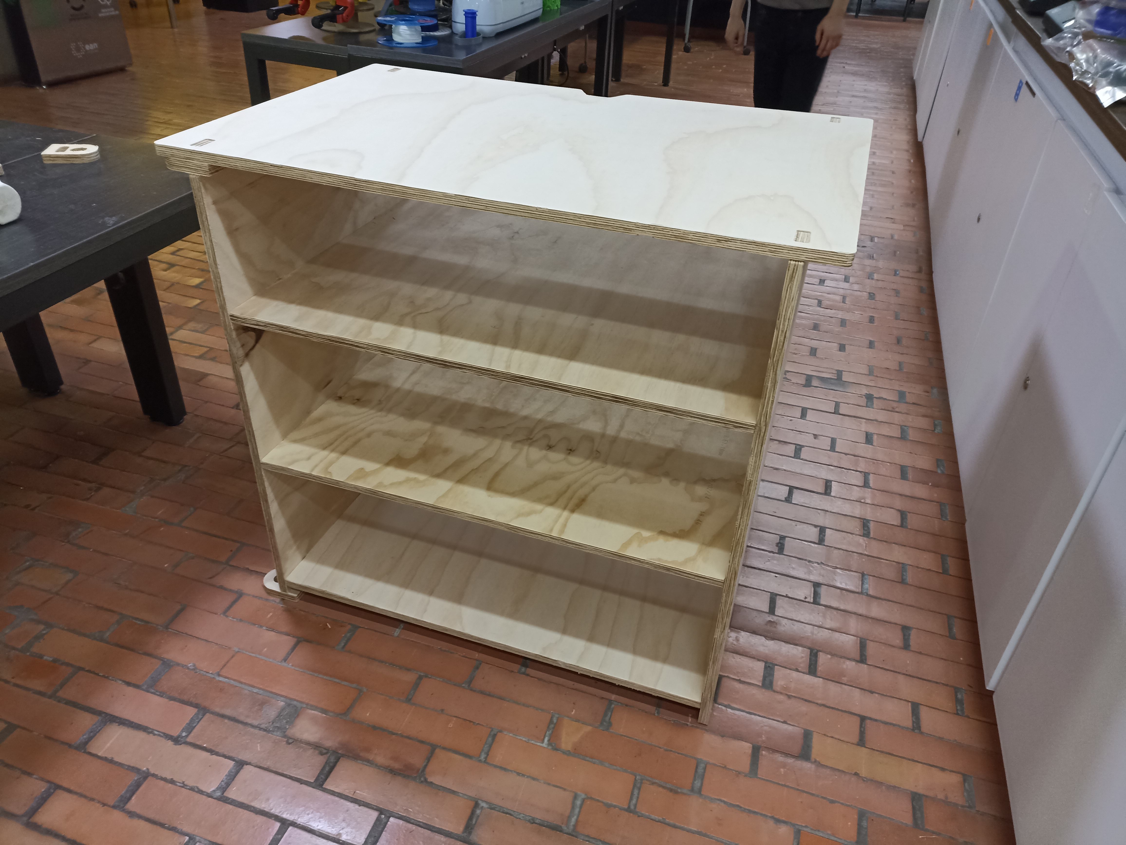
Image 21 – Fully assembled furniture piece
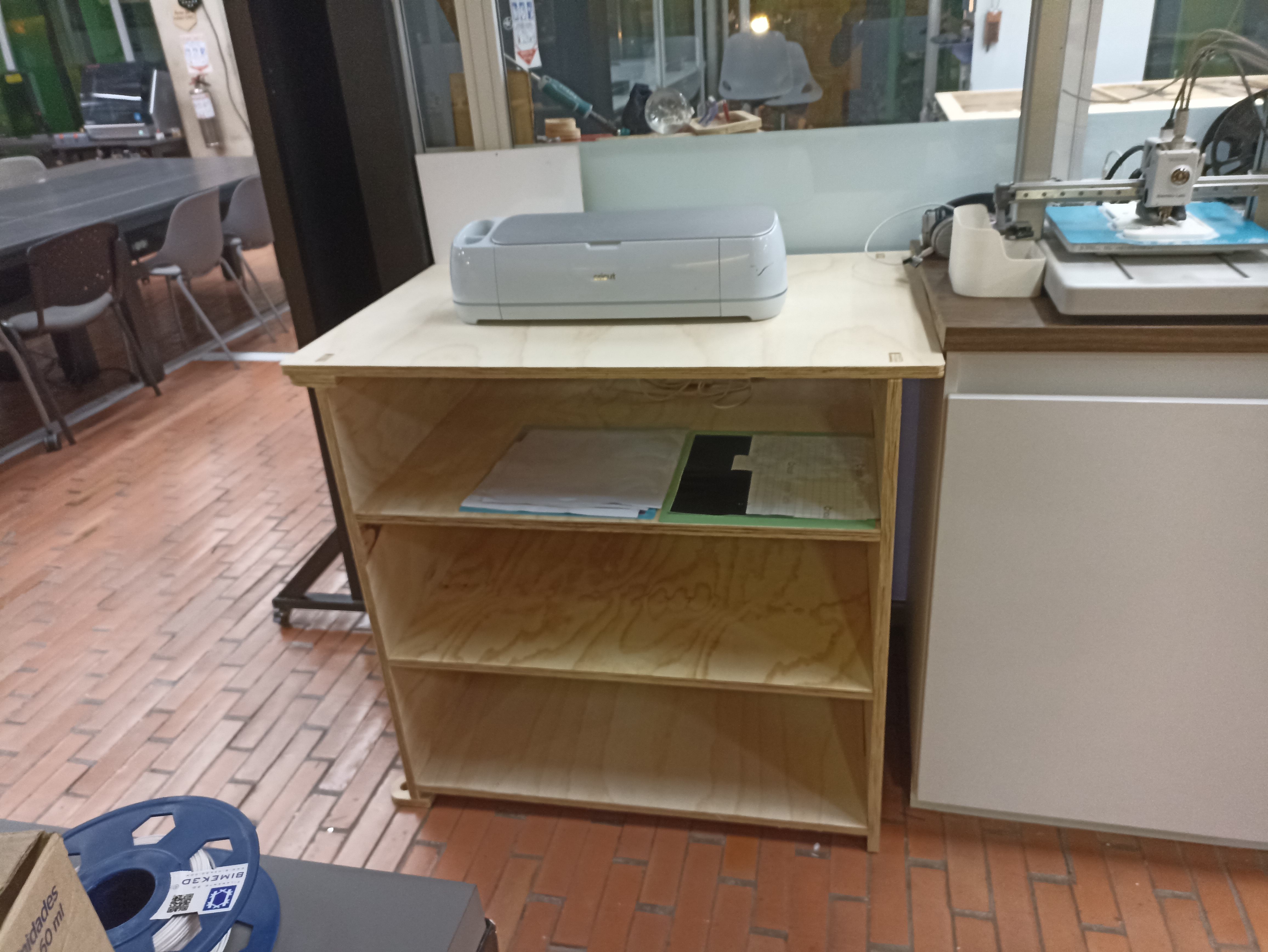
Image 22 – Final result: vinyl cutter in its new dedicated station
Conclusions
Personal Reflections and Lessons Learned
Designing and building furniture may seem simple at first, but it actually involves many critical factors — the machine, the tool, the material, the tolerances, and especially the assembly logic. It’s essential to think carefully about how the parts will come together before cutting, otherwise the process can quickly become overwhelming.
Thanks to previous experiences building a similar structure, I already had an idea of how to visualize this project in 3D and anticipate potential issues. This time, I didn’t face any incidents during the cutting or assembly process, but in the past I have — including breaking tools due to mistakes in CAM setup or stock calibration.
I believe those past mistakes helped me approach this project with greater awareness and precision. Especially when working on something as large and structural as a piece of furniture, experience and attention to detail really matter.
I also appreciate how this task challenged me to leave my comfort zone. The CNC machine used here is one I tend to avoid due to its size, noise, and power — and because of the fear of breaking expensive tools. But this week helped me overcome those fears and gain more confidence in handling complex jobs.