...

Group Assignment 7

Group 1

  • Evelyn Cuadrado

Group 2

  • Armando Calcina

Group 1

Evelyn Cuadrado

For the group assignment, I gave a talk on workplace safety and health, as at the Fab Lab iFurniture, we consider this a fundamental activity. Additionally, I conducted tests on runout, alignment, fixturing, speeds, feeds, materials, and toolpaths for our machine.

1. Introduction to Lab Safety

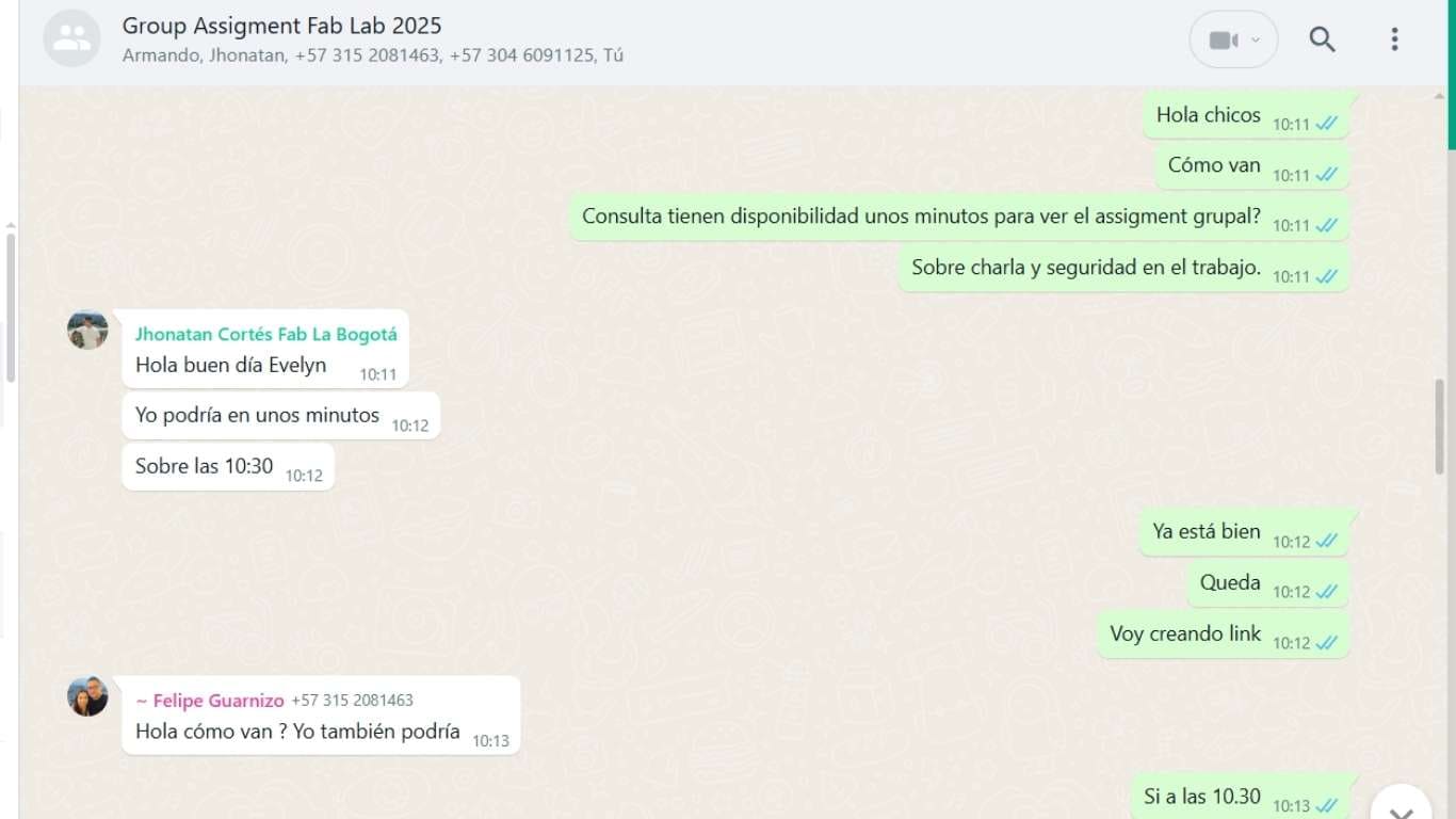
For the group assignment, I organized a meeting with my academy colleagues via WhatsApp to coordinate and set a specific date to discuss the topic of occupational health and safety. For this, we gathered with Jonathan and Andrés from Colombia and Armando from Peru (Huancayo). Jonathan gave me a very nice comment, as this presentation was very useful to him for implementing some ideas at Fab Lab Colombia.

Those words were really motivating, as we realize that we are doing things right. It’s a boost to keep working with more dedication and continue learning and improving in what we do.


As Fab Manager at Fab Lab Fab Lab iFurniture, one of my main responsibilities is to give safety talks to the team, focusing on risk prevention. It is crucial that everyone thoroughly understands the physical spaces in which we work, as well as the specific safety measures for each area. Taking the appropriate precautions is essential to minimize risks and ensure a safe working environment. Safety is a priority, and making sure that everyone is well-informed and prepared is key to preventing accidents and promoting a healthy workplace.

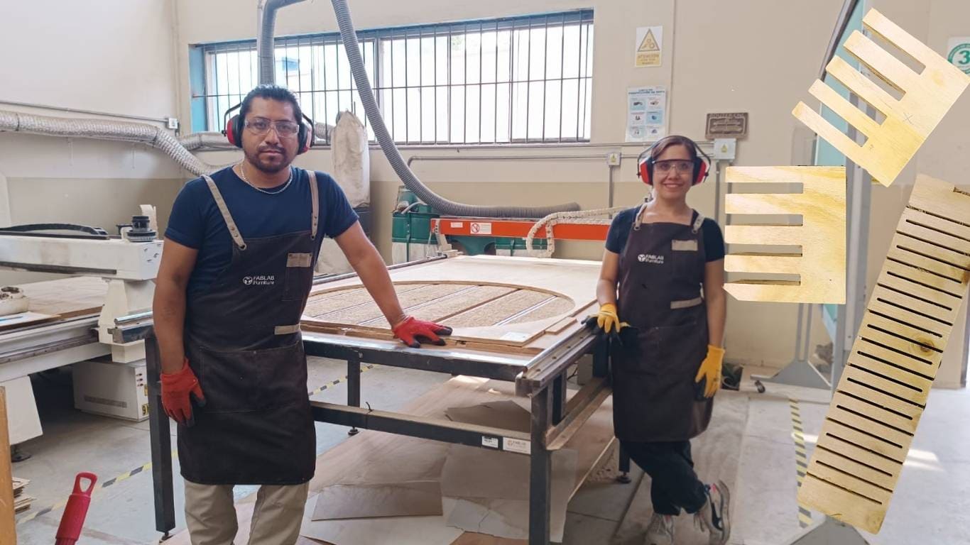
Additionally, I conducted a training workshop for my colleagues at the academy with the goal of deepening our understanding of occupational safety and health related to machinery use. During the workshop, we covered the main safety measures to follow in the lab, such as the proper use of personal protective equipment (PPE), procedures to prevent accidents, and safe practices when operating machines. We also discussed the importance of maintaining a safe work environment and how to identify potential hazards. It was a great opportunity to reinforce the importance of safety at work and ensure that everyone was well-informed about how to prevent accidents. These types of training contribute significantly to fostering a culture of safety and responsibility in the workplace.


Here is a summary of the topics covered in the talk:

Safety Signs:

Personal Protective Equipment (PPE):

PPE is essential for protecting workers from potential risks. These include gloves, helmets, safety glasses, boots, masks, among others, depending on the task being performed.
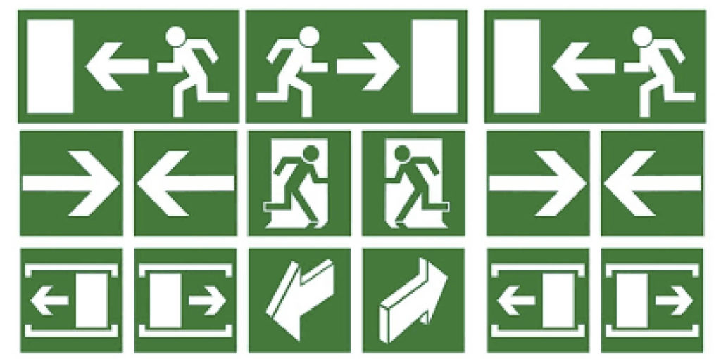

Evacuation Signage:

Evacuation signs are crucial for guiding staff in an emergency, showing routes and exits to ensure a quick and orderly evacuation.

Link of the image

Fire Extinguishers:

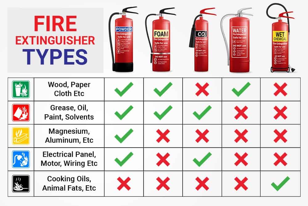
Fire extinguishers are key tools in the fight against fires. They must be placed in strategic locations, easily accessible, and staff should be trained in their proper use.

Link of the image

OCCUPATINAL SAFETY AND HEALTH


With this, I would be concluding the topic of occupational health and safety at work. Now, I will proceed to document the signage in the Router area.


Safety Signage in the CNC Router Area:

We have a CNC Router machine at Fab Lab iFurniture, located in a spacious and well-ventilated area designed to ensure a safe and efficient working environment. Safety when using this machine is a top priority, so various safety signs have been installed in the area to warn of the existing risks.

Here we can see the area marked by yellow and black stripes, where the CNC Router of the Fab iFurniture is located.


To optimize space within the Fab, we created preventive stickers. One of them clearly states DO NOT PLACE ANYTHING ON THE MACHINES to prevent obstructions and ensure that the machines remain free from items that could interfere with their operation.


Additionally, the machine is equipped with electrical hazard signage and has a main control panel for its operation, ensuring safe and proper use of the equipment.


The environment around the CNC Router machine is equipped with signage reminding the mandatory use of Personal Protective Equipment (PPE), ensuring the safety of operators at all times.


2.Introduction to the Fab Lab iFurniture Router

The structure of the CNC Router is manufactured in Peru, while the DSP control system comes from China. The DSP control system is known for its high precision and reliability, widely used in numerical control machines. The combination of a robust structure made in Peru and an efficient control system ensures optimal performance in manufacturing processes. With a cutting area of 1220 mm x 2440 mm, it is capable of handling a wide range of medium to large-scale projects, offering excellent precision and performance.

A CNC Router can work with materials such as wood, plastics (acrylic, PVC), light metals (aluminum), and composites (carbon fiber). It is also useful for cutting foam, leather, and some resin composites. However, extremely hard materials like ceramic or concrete are not suitable for this type of machine.

The material thicknesses that can be used on a CNC Router typically range from 3 mm to 18 mm. To ensure that the wood remains fixed and stable during the cutting or engraving process, it is secured to the work table with screws, preventing it from shifting or warping. This technique ensures precise cuts and minimizes potential errors during operation.


Technical Specifications of the CNC Router Fab Lab iFurniture:

Specification Details
Cutting Area: 1220 mm x 2440 mm x 150 mm
XY Positioning Speed: Variable, max. 1800”/min
Z Positioning Speed: Variable, max. 900”/min
Input Voltage: Single-phase 220V

The operation of the CNC Router consists of 4 key steps:

  1. Project Design: The piece is designed using CAD/CAM software and then converted into G-code, which is the language the machine understands to carry out the operations.
  2. Machine Preparation: In this stage, the necessary parameters for the machine operation are set, such as cutting speed, depth, feed rate, and the selection of the appropriate tool.
  3. Milling and Cutting: The machine performs the milling and cutting operations according to the provided design, following the G-code.
  4. Verification and Adjustments: Once the cutting is done, the piece is verified to ensure it meets the specifications. If necessary, additional adjustments are made to the machine parameters.

The router bit available at FabLab iFurniture has a diameter of 3.175 mm, allowing for precise cuts and details in a wide range of materials.


The router's sensor is exposed, so frequent passage on the left side of the machine should be avoided to prevent interference or damage.


The electrical panel of the CNC Router is manufactured in Peru, using locally available components specifically designed for the operation of this type of machine, ensuring its reliability and efficiency.


2.1 Machine Alignment

First, we manually align the X axis arm. On the Router, there are guide lines that will help us perform this process with precision.


To start configuring and calibrating the XYZ axes, we click on 'All Axis Home,' which automatically positions all axes to their home positions, ensuring correct alignment before beginning the work process.


We align the X and Y axes to 0.000 and then press the 'XY ➡️ 0' button. This way, we correctly set the reference point for both axes.


To set the Z axis, we carefully lower the axis using the control. When the bit is close to the selected material (in this case, a material with a thickness of 15 mm), we manually adjust the bit until it makes contact with the material.


After completing the manual setup, I press the 'Z ➡️ 0' button, and now the Z axis is calibrated to 0.000.


Once this is done, we raise the Z axis to +20.000, which is the standard height at which the Fab Lab iFurniture machine operates. Then, we return to the origin to begin working with the machine.


To open the file, click on the 'Run/Pause/Delete' button, and then press only the green button.


2.2 Design Workflow in Rhino

The process begins in Rhino, a 3D modeling software used to create detailed and complex part designs. Once the design is completed, it's organized into different layers for cutting, engraving, and drilling. The design is then exported as a DXF file, which contains the necessary vector information for manufacturing.

Here, I created a simple design for my assignment, using two examples: one showing an interlocking design and another created to generate curves.


2.3 Manufacturing in ArtCam

The software I used for designing my tests is ArtCAM, a powerful CAD/CAM tool specifically geared towards creating 2D and 3D parts for CNC machines. ArtCAM offers great flexibility and precision in creating complex patterns and fine details, thus streamlining the manufacturing process.

To begin the design and preparation process for the CNC machine, I import the file into the ArtCAM software. Once imported, I set up the machine parameters, including material type, tool size, feed rates, and cutting depth. ArtCAM then generates the G-code, which guides the CNC machine through the cutting and milling process.


ArtCAM Configuration Process for Creating G-Code

CNC Router Configuration

Recommended Machining Parameters:

These values are suitable for a 3.175 mm bit in wood and may vary depending on the material and machine stability.

Next, I go to Toolpaths and select Save Toolpath. This opens a window where I save the file in G-code format. To organize the files, we use specific codes to identify the type of operations being saved. For example: EX for exterior line, IN for interior line, and DES for roughing. Once the configuration is complete, we copy the G-code files to the Router machine's USB.


2.4 Cutting Tests in CNC Routing

For this activity, I used the slot join and a flexible design. The slot join is a technique that allows pieces to be joined simply and efficiently, ensuring precise alignment. On the other hand, the flexible design adapts to different configurations and is useful for making adjustments during the manufacturing process, allowing greater versatility in the construction of the project.

The software used at the Fab Lab iFurniture is ArtCAM, a powerful CAD/CAM tool specifically geared towards creating 2D and 3D parts for CNC machines. ArtCAM offers great flexibility and precision in creating complex patterns and fine details, streamlining the manufacturing process.

For this activity, I used the slot join and a flexible design. The slot join is a technique that allows pieces to be joined simply and efficiently, ensuring precise alignment. In addition, the flexible design adapts to different configurations, making it easier to adjust during the manufacturing process and providing greater versatility in project construction. However, I forgot to use the chamfer, so it's important to note this observation and correct it in future tests, as this detail would have optimized the functionality of the pieces.

Before starting the cutting process, it is essential to place the material on the sacrificial bed and secure it with screws. This step is crucial to ensure that the material does not move during the cutting process, which guarantees precision and quality in the work.


The joint is a connection method where components fit precisely to ensure stability without adhesives or screws. Parts are designed to fit into slots or notches, and anchoring involves securing them in place using pressure, gravity, or locking mechanisms. This technique is common in furniture and industrial components, offering strength, durability, and easy assembly without extra tools.


To conduct the material cutting tests, I chose 15 mm phenolic plywood, as the thickness I will use for my individual assignment will be this size. This material will allow me to check the precision and effectiveness of the CNC Router, ensuring that the cutting parameters are suitable for the specific thickness used in the final project.


With all of this, I was able to conduct joint fitting tests using 15 mm thick plywood phenolic pine material. Additionally, I carried out another test by cutting a prototype to create curves.


For this project, I used two types of joins: slot join and flexible join. Both joining techniques are used to assemble the pieces precisely and functionally.

  • Slot Join: This technique involves creating a slot or groove in one piece and a corresponding fitting in the other. This type of joint is commonly used in structures where stability and precise alignment are required. Technically, the slot is made with an "L" or "U"-shaped cut, allowing the pieces to fit securely and stably. It is ideal for applications where rigidity and ease of assembly are essential.
  • Flexible Join: This type of join allows some flexibility in how the pieces connect, which is useful for enabling movement or for applications that require easy and quick adjustments. Flexible joins are particularly useful when the pieces need some play or adaptability in their assembly, without compromising the overall stability of the structure.


  • Group 2

    Armando Calcina

    The group training on safety measures in the workplace of a Fablab was given by Evelyn Cuadrado, manager of Fablab iFurniture. This talk was interesting because of the way she shared her experiences and knowledge in the workplace on computer-controlled machines dedicated to CNC routing and cutting.

    On the other hand, to develop this task, I visited the fablab of the Continental University, located in the city of Huancayo, where they provided me with the support and assistance to complete the assigned task.

    1. laboratory Safety Training

    Training and instruction in CNC machine safety regulations are essential to ensure safe and efficient operation of these machines. Operators and other personnel involved must receive adequate training to understand and comply with established safety regulations.


    Personal protective equipment (PPE):

    Personal protective equipment (PPE) is important because it protects the operator from potential injuries while working with machines and tools. In the case of CNC machines, it helps prevent accidents caused by chips, noise, moving parts, or machine failure.


    Although not integrated into the machine, the following are required:

    • Safety glasses
    • Hearing protection
    • Safety footwear
    • Close-fitting clothing without dangling items.


    Fire Protection Systems:

    The laboratory has fire protection measures in the work environment, such as fire extinguishers and fire detection and alarm systems.


    Adequate Signage:

    The work environment must have clear and visible signage indicating hazard areas, emergency exits, evacuation routes, and the location of safety equipment.


    Warning signs

    Indicate potential hazards or risks, such as "Electrical Hazard" or "PPE Required"


    Emergency Signs

    The laboratory has evacuation plans in place in the event of an event or disaster, as well as emergency exits, the location of fire extinguishers, and first aid.


    A Risk Map

    The laboratory has a visual tool that identifies, classifies, and locates hazards present in the work area. It helps prevent accidents and make more informed safety decisions.


    Preliminary Inspection:

    Safety signage for CNC machine use is essential to warn, inform, and protect operators and bystanders. It helps reduce the risk of accidents and maintain a safe and organized work environment.


    Safety Procedures:

    Safety signage for CNC machine use is essential to warn, inform, and protect operators and bystanders. It helps reduce the risk of accidents and maintain a safe and organized work environment.


    2. Description of the ShopBot PRSalpha 96 x 48 CNC machine

    The ShopBot PRSalpha 96 x 48 is a high-performance computer numerical control (CNC) machine designed for precise cutting, engraving, and machining in materials such as wood, MDF, plastics, composites, and non-ferrous metals. Its working size of 96 x 48 inches (approximately 2.4 x 1.2 meters) allows for processing large-format panels, making it an ideal tool for professional woodworking, furniture manufacturing, industrial prototyping, and digital design applications.

    Unlike a CNC milling machine, CNC router machining depends on the material it can handle. CNC routers are not designed for hard materials, such as hard metals like steel and titanium. These machines are generally reserved for materials like wood, plastic, and foam, but they can also work with soft metals like aluminum.


    Technical Specifications of the ShopBot CNC Router

    # Specification Details
    1 Working Area (X × Y × Z) 1 220 mm × 2 440 mm × 150 mm
    2 Spindle Power 3.2 kW (Variable Speed)
    3 Max. Rapid Traverse 12 m/min
    4 Positioning Accuracy ±0.05 mm
    5 Repeatability ±0.02 mm
    6 Drive System Rack & pinion (X and Y), Ball screw (Z)
    7 Tool Change Manual collet change (ER‑32)
    8 Control Software ShopBot Control (ShopBotEASY compatible)
    9 File Formats Supported .SBP, .NC (G‑code), .DXF, .SVG
    10 Power Requirements 230 VAC, 1 phase, 16 A
    11 Machine Dimensions (L × W × H) 3 200 mm × 1 600 mm × 1 700 mm
    12 Machine Weight ≈ 1 200 kg

    Software VCARVE PRO

    At Continental University's FAB Lab, we use VCarve Pro, a computer-aided design and manufacturing (CAD/CAM) software widely used for creating 2D and 3D designs and generating toolpaths for CNC machines. When using the ShopBot CNC machine, VCarve Pro allows you to design parts with great precision and prepare machining files for the ShopBot to execute when cutting, engraving, or milling materials such as wood, plastic, or metal.

    The VCarve Pro work environment is designed to facilitate vector design, toolpath editing, and control file generation for CNC machines, such as the ShopBot. It is intuitively organized into different areas and panels that allow the user to control every stage of the digital manufacturing process.


    Once ready in the Vcarve Pro work environment, I created a simple design for the task, using two examples: one showing an interlaced design and another created to generate curves.


    We adjust the coordinates for each of the axes: X: -0.000 mm, Y: -0.000 mm, and Z: 20.324 mm. These indicate the current position of the tool relative to the zero point (origin). In this case, X and Y are at zero, and Z is elevated (at 20.324 mm).


    The design created is adjusted according to the configured coordinates.


    The image shows the cut of the design, made on the pressed wood plate whose thickness is 15mm.


    The image shows the comb molds, which are used to check the precision and efficiency of the CNC milling machine, ensuring that the cutting parameters are suitable for the specific thickness of the material used, in this case, pressed wood.


    For the second As you can see, this test was carried out using 15 mm pressed wood material. Its flexibility is clearly noticeable.


    Group 3

    Andrés Felipe Guarnizo Saavedra

    Michael Sebastián Torres

    Jhonatan Cortes

    Lab Safety Training

    For the first part of this week’s group assignment, focused on safety training, Evelyn shared a set of slides covering the key safety protocols we must follow in the lab. During the session, all participants were able to discuss and reflect on the importance of safety when operating CNC machinery and working with large materials. It was a valuable moment to align expectations and responsibilities before using the equipment.

    Safety training presentation and discussion in the lab

    Safety presentation led by Evelyn with active discussion among participants.

    Safety Walkthrough & Emergency Equipment

    As part of the safety training, we took a walkthrough of the FabLab facilities to identify important signage and emergency tools available on site. We discussed the purpose and placement of each safety element. For example, the image below shows a fire extinguisher located near the collaborative work area, clearly marked and easily accessible in case of emergency.

    Fire extinguisher located near FabLab workspace

    Fire extinguisher positioned near the collaborative work area, with visible signage.

    Another critical safety element available in the FabLab is the fire hose cabinet, which contains a hose and water supply to be used in case of fire emergencies. It is strategically located and properly signaled to ensure fast access when needed.

    Fire hose cabinet available in the FabLab

    Fire hose cabinet equipped for use in emergencies, with water supply and signage.

    In the large-format CNC cutting area, we also identified a dedicated fire extinguisher close to the machine. Since the area was already reserved for use, we observed that personal protective equipment (PPE) such as ear protection and safety glasses were properly in place, ensuring readiness for safe operation.

    Fire extinguisher and PPE in the CNC work zone

    Fire extinguisher and personal protective equipment visible in the CNC area.

    The laser cutter experienced a minor fire incident in the past, which left a visible mark on the upper left corner of its door. This serves as a clear reminder of the importance of strict safety protocols. Notably, the machine is equipped with a safety interlock system that prevents operation unless the door is completely closed—an essential feature to protect users during cutting operations.

    Slight damage on CNC door and interlock system

    Upper left corner of the laser cutter door showing heat damage from a past incident; machine includes a door interlock safety system.

    An additional safety measure implemented for the laser cutter machine is a surveillance camera installed directly over the work area. This camera allows the operator to remotely monitor the machine’s operation in real time from the control computer. The live video feed appears as a floating window on the lab's main screen, ensuring continuous visibility and quick response to any irregularities during the cutting process.

    Camera monitoring CNC machine shown on lab display

    Surveillance feed of the laser cutter area shown on screen for remote and continuous monitoring.

    Another important safety measure observed during our training was the clear identification of specific areas within the FabLab. Spaces containing potentially dangerous equipment such as saws or cutting tools are properly marked and access is restricted to authorized personnel only. This helps prevent accidents and ensures that only trained users operate such machinery.

    Sign indicating restricted access in areas with cutting tools

    Safety signage showing restricted access to areas with high-risk tools.

    We also observed that the emergency exits within the FabLab are properly marked and easily visible. These signs are essential for guiding occupants quickly and safely out of the building in case of fire, power failure, or any other emergency situation.

    Emergency exit sign visible in the FabLab

    Clearly marked emergency exit within the FabLab facilities.

    First Aid Station and Medical Supplies

    As part of the safety infrastructure in our FabLab, we also have a fully stocked first aid station located near the entrance. Its location is clearly marked so that all users can quickly identify and access it in case of an emergency.

    The station includes a wide range of supplies designed for minor lab-related incidents such as cuts, punctures, and small burns. In addition to basic materials, it also contains a stretcher and orthopedic neck braces for stabilization during more serious situations.

    First aid kit and FabLab entrance

    Large first aid kit and entrance area of the FabLab for quick emergency access.

    Dedicated CNC Area Fire Extinguishers

    The CNC machining area is protected by two fire extinguishers: one placed directly within the CNC working space and another positioned near the entrance of the area. This setup ensures immediate access from both inside and outside the workspace.

    These fire extinguishers are critical due to the presence of large wooden materials, high-speed spindles, and airborne dust, all of which increase fire risk. The placement supports rapid intervention in case of emergencies.

    Walkthrough video showing the CNC room entrance and fire extinguishers.

    Environmental Ventilation and Dust Extraction

    The CNC room includes an active air ventilation system to regulate heat and maintain safe air quality during extended machine operation. The system reduces the build-up of heat generated by the spindle, vacuum, and motors.

    In addition, a powerful dust collector is installed to remove fine particles from the cutting process. While highly efficient, small traces of dust may occasionally escape into the environment, which is why the ventilation system plays a complementary role.

    Ventilation system and power panel signage

    Panel and signage for ventilation and environmental safety in the CNC room.

    CNC Area Containment and Restricted Access

    The CNC machining space in our FabLab is located in a recently built and fully enclosed room. Although final safety signage and floor markings are being installed, the room already provides critical physical separation from the rest of the lab.

    Only authorized and trained personnel are allowed to enter this area, as the enclosure helps prevent accidents and avoids unintentional access to the machine’s moving zone. The clear enclosure serves both operational safety and user protection.

    CNC machine inside enclosed workspace

    CNC machine enclosed in its own dedicated space for safety and access control.

    a

    Router Cnc Fablab Ean

    Machine Overview

    During this week, we focused on understanding and documenting the operation of the CNC machine model WS2-1325ATC. This large-format machine is capable of milling large materials thanks to its working area of approximately 3 meters in length and 2 meters in width.

    The machine is equipped with a vacuum pump that securely holds the material in place on the bed, ensuring stability during the milling process. It also includes side pneumatic pistons that, with the help of an air compressor, provide additional mechanical clamping when needed for higher stability.

    General view of the WS2-1325ATC CNC machine

    Particle Extraction and Tool System

    To maintain a clean and safe working area, the machine features a particle extraction system composed of a dual turbine with dust collection bags, as shown in the image below. This system is essential for removing chips and dust generated during milling, improving visibility and reducing the risk of damage or accidents.

    It also features an Automatic Tool Changer (ATC), which optimizes the workflow by automatically switching tools based on the CAM file configuration.

    Particle extraction system and compressors

    Learning Outcomes

    Personal Protective Equipment (PPE)

    For the safe operation of the CNC machine, it is mandatory to wear the appropriate personal protective equipment. In the image below, we can see a team member equipped with the standard PPE required in the Fab Lab environment:

    Operator with PPE in front of the CNC machine

    Wearing the correct PPE not only ensures compliance with safety standards but also promotes responsible and professional lab practices.

    Machine Calibration (Homing Process)

    Before any machining operation, it is necessary to perform a homing procedure to establish the origin coordinates for each axis (X, Y, Z). This ensures that the machine references its mechanical limits and operates within the correct coordinate system.

    On the machine’s touchscreen interface, we access the homing process by pressing two specific buttons:

    This process moves the spindle to its reference points along all axes, defining the machine’s zero position. The image below shows the control panel where the homing functions are activated.

    CNC machine touchscreen interface showing homing buttons

    After this step, the machine is ready to receive the job file and perform accurate cutting operations based on the defined origin.

    Tool Height Calibration and Delta Z Setting

    After the machine is homed and initialized, the next step is to calibrate the Z-axis height of the tool. This process is essential to ensure that the cutting tool knows the surface height of the material to avoid cutting too deep or too shallow.

    On the control interface, we access the Auto Tool Function panel. We begin by pressing Start to initiate the automatic measurement of the tool length. The spindle moves to a designated reference area (top-left corner of the machine bed) and measures the tool height by making contact with a metallic sensor, as shown below:

    Tool height measurement with contact sensor

    Once the tool height is measured, we manually move the tool tip above the material, lowering it slowly until it almost touches or barely scratches the surface. At that point, we press the Delta Z Set button to define the actual material height relative to the tool length previously recorded.

    This two-step process ensures accurate depth reference for all cutting operations:

    1. Reference Tool Height: Automatically measured using the metallic sensor.
    2. Delta Z: Manual fine adjustment for material surface height.
    Tool manually aligned over material for Delta Z

    By completing this calibration, the machine can correctly interpret the surface of the stock material and execute precise Z-axis movements during the milling job.

    Tool Selection and Cutting Parameters

    For the cutting operation, we selected a 6 mm diameter flat end mill with two flutes, made of high-speed steel (HSS). This tool is suitable for cutting plywood and similar wood materials, offering a good balance between material removal and surface finish.

    Tool mounted on CNC spindle

    The tool properties used in our CAM setup were as follows:

    Tool geometry setup in CAM software

    Feed and Speed Settings

    The cutting parameters were configured manually in the CAM software to match the material and tool used. The following settings were applied:

    Feed and speed settings in CAM software

    These values were chosen to ensure a clean cut on plywood without causing burning, chipping, or excessive tool wear. The spindle speed was optimized for the 6 mm bit and the feedrate was tested during previous jobs to validate smooth operation.

    Press-Fit Test Design (Fusion 360)

    Before performing the final cuts, we designed and milled a Press-Fit Test in Fusion 360. This test helps determine the ideal fit between interlocking parts, considering the specific tool, material, and machine tolerances. The goal is to find which dimension provides the perfect balance between friction and ease of assembly for our plywood.

    Press-Fit Test Design in Fusion 360

    The test consists of several rectangular slots and tabs with varying widths, ranging from 16.15 mm to 15.85 mm. Each pair was separated by 0.05 mm, allowing us to observe how subtle variations affect the final fit when assembled.

    Additionally, we included a reference pattern (right side of the image) with standard hole dimensions and spacing to later test the accuracy of drilled components.

    This design was exported as a DXF file and then prepared in the CAM environment for toolpath generation. The results helped us identify the most accurate tolerance for our material and tool combination.

    CAM Setup and 2D Contour Operation

    Once the design was complete, we moved to the Manufacture workspace in Fusion 360 to generate the toolpaths required for CNC cutting. We created a new setup and selected the 2D Contour operation, which defines how the cutting tool will follow the profile of the geometry.

    Fusion 360 2D Contour operation setup

    In this operation, we adjusted the following parameters:

    We also disabled the lead-in and lead-out options to keep the toolpath clean and direct. Once the parameters were configured, we generated the toolpath and performed a simulation to visualize the operation before exporting the G-code.

    The simulation confirmed the correct entry points, tool movement, and depths, helping us validate the strategy before moving to the physical cutting stage.

    Physical Cutting and Results

    Once the toolpaths were simulated and validated, we proceeded to execute the physical cut using plywood material. The press-fit test file was loaded into the CNC machine, and the spindle performed the cutting operation as expected.

    Press-fit slots after cutting

    After cutting, we tested several pieces of wood with the different slot sizes. The goal was to determine the optimal press-fit tolerance. The results were as follows:

    Press-fit test with wood insert Top view of test results

    We also performed a full-scale cut of a larger shape to validate the machine's behavior during extended operations. The paths were followed smoothly and the part was successfully extracted.

    Final large piece cut on CNC

    Conclusion

    This group assignment provided valuable hands-on experience with the complete CNC machining workflow, from design and toolpath simulation to physical cutting and result analysis. We confirmed that material tolerances vary and must be tested for each job. In our case, a 15.90 mm slot width was the most effective for press-fit joints on plywood using a 6 mm flat end mill and 19000 rpm spindle speed.

    We also reinforced our understanding of safety procedures, tool calibration, and the importance of proper setup in CAM software to ensure efficient and accurate CNC operations.


    Group 4

    Sandra Hipatia Nuñez Torres

    Manuel Ignacio Ayala Chauvin


    Our CNC Adventure: Learning, Testing, and Building

    1. The First Step: Lab Safety

    Before diving into the CNC machine, we had to make sure we weren’t risking life and limb. Safety first! We geared up with protective goggles, gloves, and dust masks. We also took the time to learn emergency procedures and how to handle tools correctly. No one wants a CNC mishap!

    2. Setting Up for Success: Runout, Alignment, and Fixturing

    We wanted our cuts to be as precise as possible, so we started by checking the machine’s runout. Using a dial indicator, we made sure everything was within 0.01mm of perfection. We carefully aligned our 9mm plywood on the work table, adjusting it with stops and clamps to ensure zero movement.

    Runout and Alignment Check

    3. Finding the Perfect Cut: Speeds, Feeds, and Toolpaths

    Now came the exciting part: setting up the machine! We chose a 6mm straight-cut end mill and programmed our speeds and feeds:

    4. Designing and Building Something Awesome

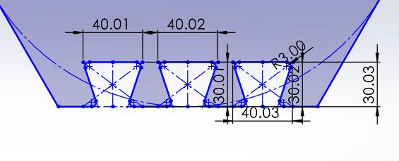
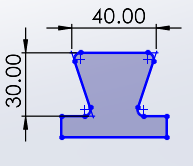
    Using SolidWorks, we designed different types of joints to test. Each one had its own personality and challenge:

    Once the design was ready, we ran a test cut on scrap material to make sure everything was perfect. Then, we watched as the CNC machine did its magic, carefully cutting each piece.

    Test Cut

    5. The Big Moment: Assembly

    After cutting all the pieces, it was time to put them together. No screws, no glue – just pure precision. We sanded the edges to remove splinters, then started assembling. It was like solving a 3D puzzle. The result: the Latin American Pavilion. Watching it take shape was incredibly satisfying!

    6. Lessons Learned

    Final Thoughts

    This wasn’t just an assignment; it was a journey. From concept to execution, watching the CNC bring our designs to life was rewarding. The best part? We built something meaningful using only smart design and teamwork.

    |