Assignments
Group Assignment:
- Send a message between two projects.
- Document your work to the group work page and reflect on your individual page what
you learned.
Individual Assignment:
- Design, build and connect wired or wireless node(s) with network or bus addresses
and a local input and/or output devices.
Week 11. Embedded Networking and Communications
Group Reflection
During this assignment, I worked remotely with Evelyn Cuadrado. Despite the
geographical distance between Colombia and Peru, we collaborated successfully using
MQTT communication over the internet. We developed a mini-project featuring a
laser-cut MDF garage controlled by a high-torque servo motor. Evelyn acted as the
publisher, sending "open" and "closed" commands from Peru using a Seeed XIAO
ESP32-C3 board, while I acted as the subscriber in Colombia using an ESP32-S3.
The subscriber code interpreted the MQTT messages and controlled several output
devices: a servo motor for opening/closing the garage, RGB LEDs for status
indication, and a buzzer for sound feedback. This experience helped us learn how
MQTT works in real-time scenarios, not just for simple data logging, but for
controlling actuators and visual elements across borders.
Beyond technical learning, it was a powerful demonstration of how connectivity
enables collaboration across countries. It showed us that designing distributed
systems using modern protocols can break barriers and expand the reach of our Fab
Lab projects.
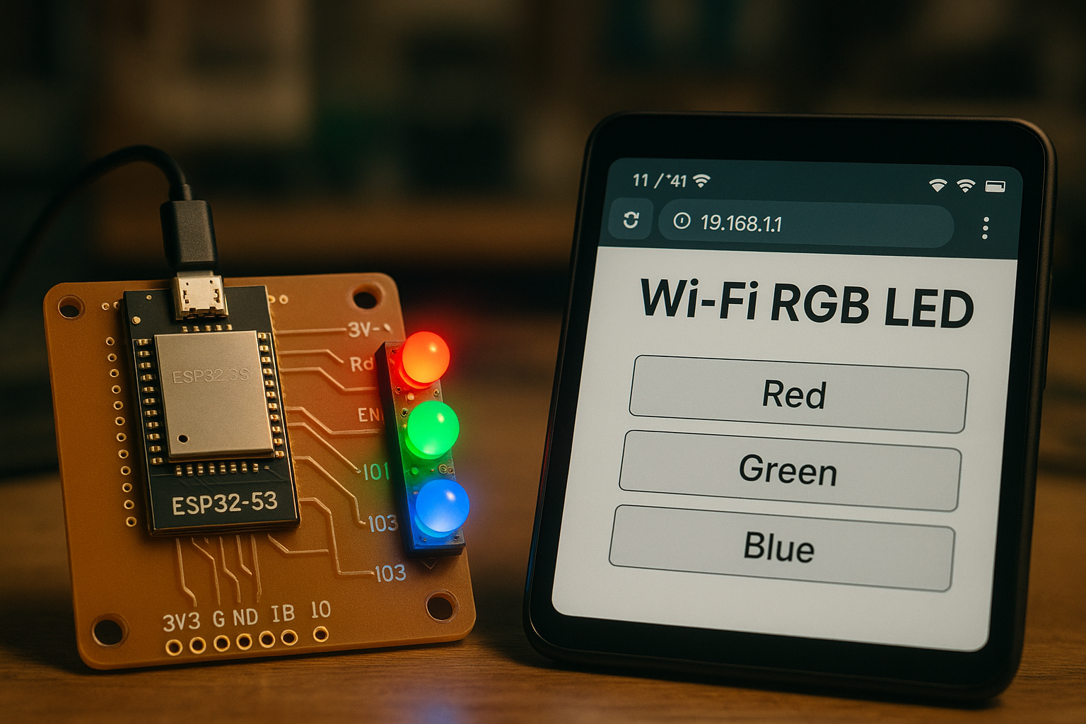
2️⃣ Introduction & Project Idea
For this week's assignment, I decided to explore a powerful feature of the ESP32-S3: the
ability to create a local Access Point (AP) without internet. While in
the group project we worked with MQTT, and many of my classmates
continued down that route, I chose to go in a different direction to learn how to build
a local wireless network hosted directly by my board.
The idea is to control an output device—in this case, a common cathode RGB
LED—via a web interface served by the ESP32-S3 itself. The microcontroller
generates its own Wi-Fi network, which I can connect to with my phone or computer. Once
connected, I access a simple HTML interface with buttons to toggle the LED colors or
activate a random color mode.
This RGB LED is already integrated into the custom PCB I designed during Week 8, with the red, green, and
blue cathodes connected to GPIOs 4, 5, and 6. I chose this project
because local AP communication is a powerful tool that I may implement in my
final project for managing admin access or maintenance tools without
internet dependency.
3️⃣ System Overview
The system designed for this assignment is based on the ESP32-S3
microcontroller, known for its dual-core processing and built-in Wi-Fi capabilities,
which are key for enabling embedded web-based control. The board hosts its own
Access Point (AP), allowing nearby devices to connect without relying
on external internet access.
The output device selected is a common cathode RGB LED, which enables
the generation of multiple colors by controlling each of the three color channels (Red,
Green, Blue) independently via Pulse Width Modulation (PWM). The RGB LED is connected to
GPIOs 4 (Green), 5 (Red), and 6 (Blue), which are already routed and
soldered on the custom PCB designed in Week
8.
The ESP32-S3 serves a simple HTML interface hosted directly on the
board. When a user connects to the ESP32's Wi-Fi network, they can open a local web page
to turn the RGB LED on or off, or to trigger a random color mode for visual
effect.
- Microcontroller: ESP32-S3 DevKit
- Output device: Common cathode RGB LED (GND shared, each color controlled independently)
- GPIO mapping: Green → GPIO 4, Red → GPIO 5, Blue → GPIO 6
- Power: 5V from USB-C + regulated 3.3V internally
- Communication: Web client served through a local Wi-Fi AP hosted by the ESP32
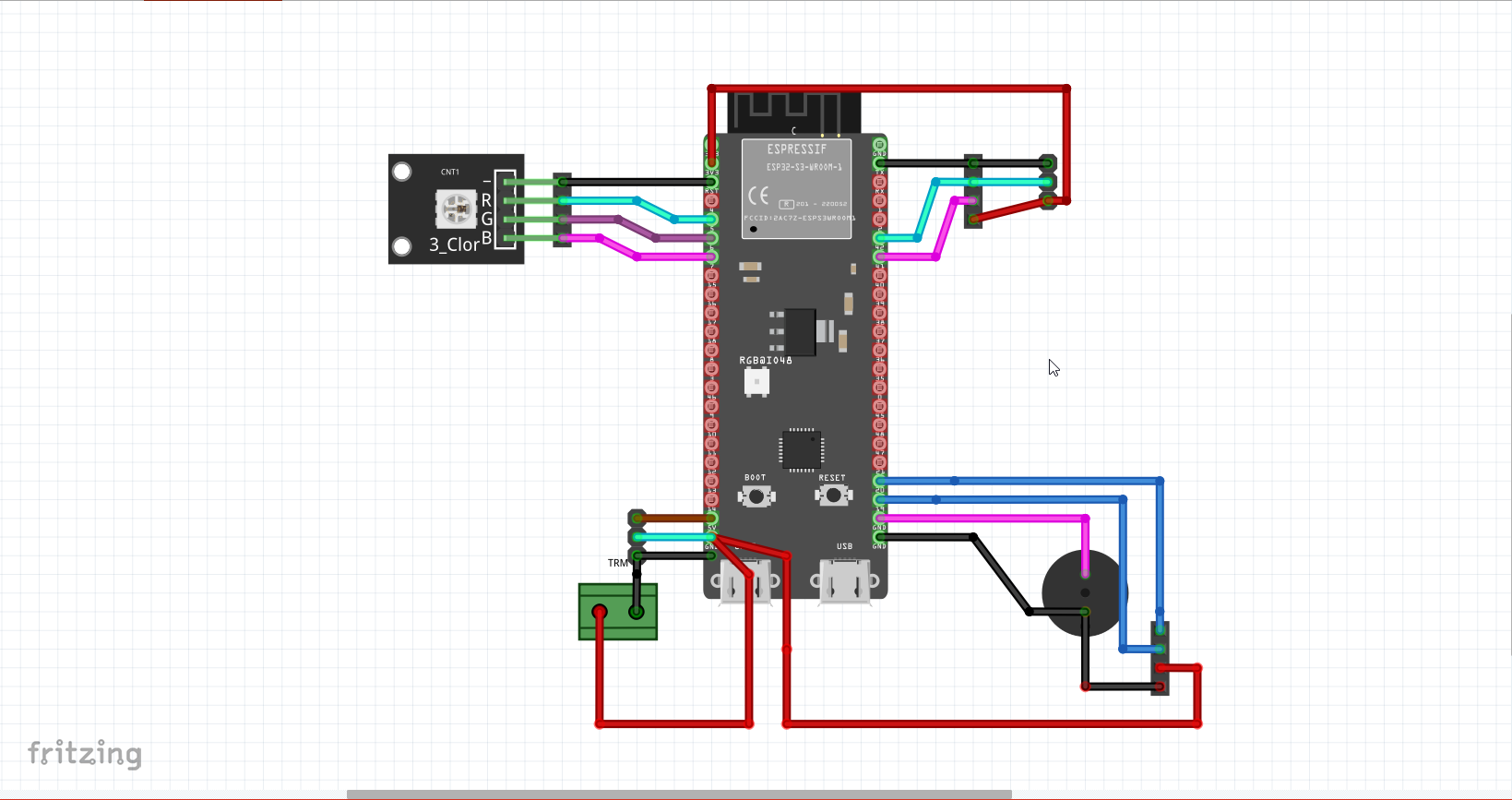
🧩 Schematic: Wiring of RGB LED with ESP32-S3
4️⃣ Wiring Diagram
- Connected Pins: The RGB LED (common cathode) was connected to GPIO 4 (Green), GPIO 5 (Red), and GPIO 6 (Blue).
- Voltage Considerations: Each LED leg includes a current-limiting resistor of 220Ω to avoid damage to the ESP32-S3 or LED components.
The LED was inserted into a breadboard and powered directly from the ESP32-S3 GPIO pins. Because it is a common cathode RGB LED, logic HIGH turns off a color, and logic LOW turns it on. All pins were correctly defined in the Arduino sketch.
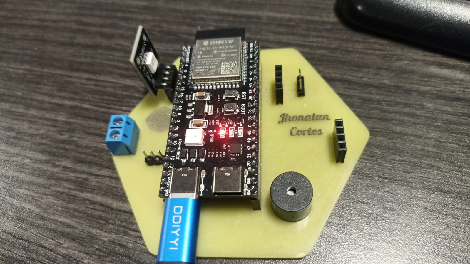
🔧 Physical setup: RGB LED on breadboard connected to ESP32-S3
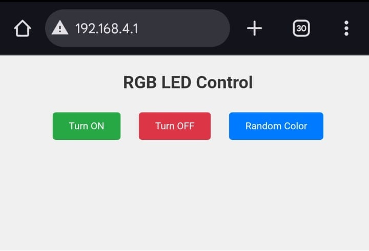
5️⃣ Web Interface Design
- HTML Interface: The ESP32-S3 serves an HTML page via a local access point, containing three buttons: ON, OFF, and Random Color.
- Interaction Logic: Each button sends a simple HTTP GET request to the ESP32, triggering an action on the server.
The design is intentionally simple for quick testing without the need for external
libraries or frameworks. The HTML is stored in flash memory using PROGMEM.
When a user clicks any of the buttons, the browser sends a GET request to endpoints like
/on, /off, or /random, and the ESP32 executes the
corresponding LED behavior.
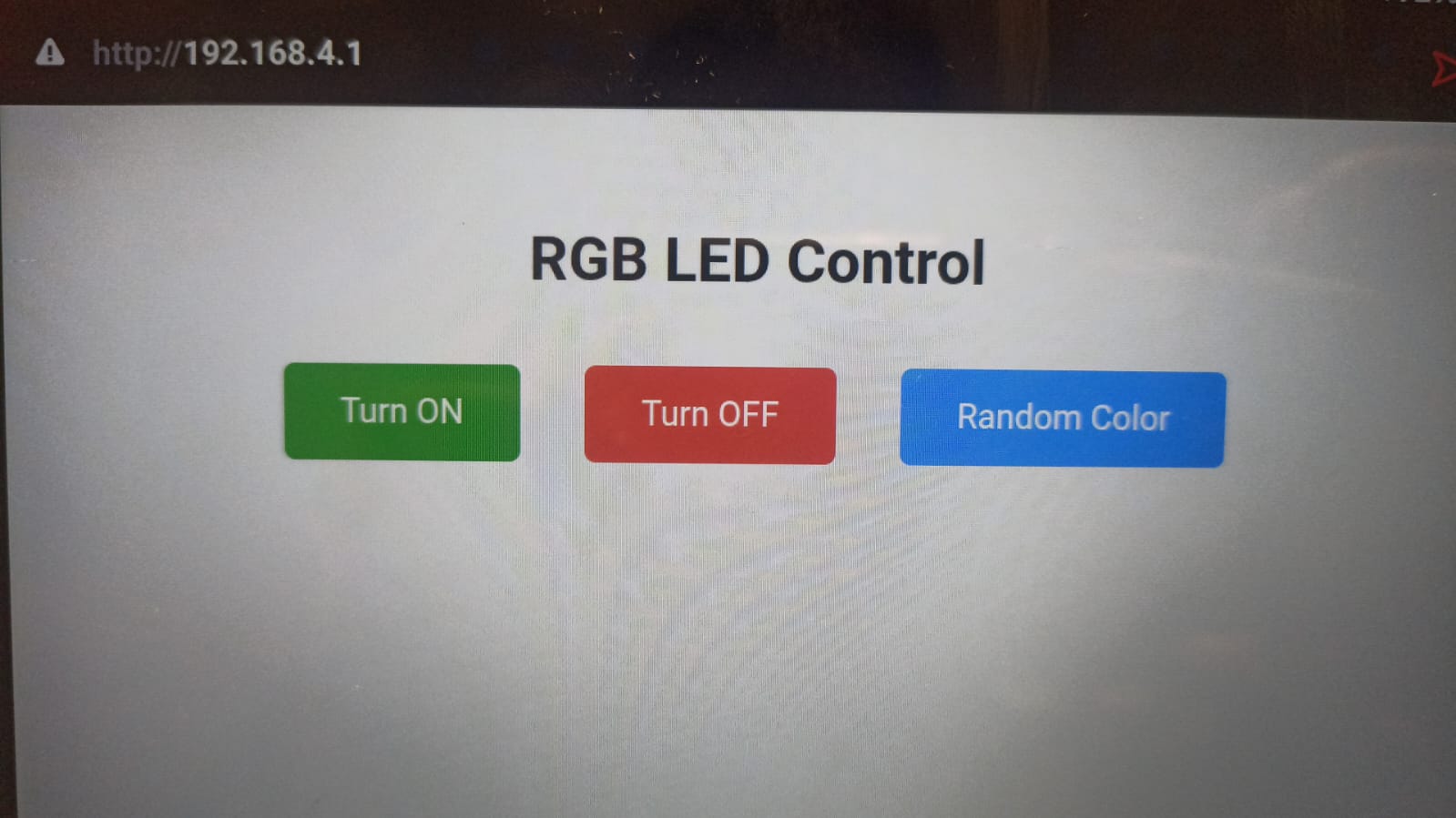
Figure – Web interface served by ESP32-S3 to control RGB LED.
6️⃣ Programming (Annotated Code)
- Libraries Used:
WiFi.hfor creating the Access Point, andWebServer.hto handle HTTP requests on port 80. - HTML Interface: Defined directly in flash memory with
PROGMEMto avoid needing SPIFFS. - Routing: The ESP32 receives requests for
/on,/off, or/randomand executes the corresponding LED action.
This code creates a local Wi-Fi network (without internet) where users can connect and interact with a webpage served by the ESP32-S3. The web interface has three buttons to control an RGB LED: turn it ON, OFF, or set a random color.
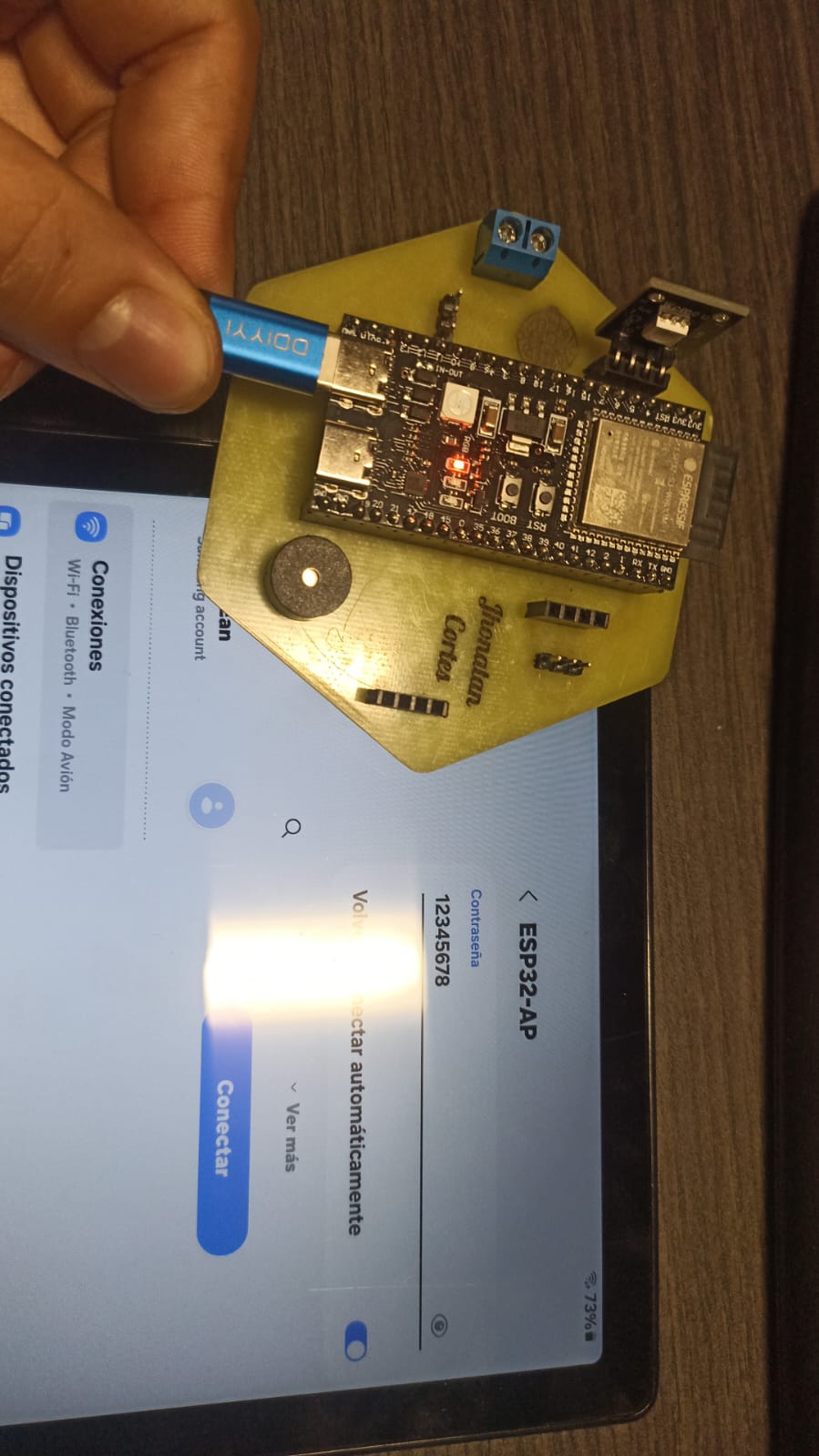
| 🔐 Access Point Info | |
|---|---|
| 📶 WiFi Network Name (SSID) | ESP32-AP |
| 🔑 Password | 12345678 |
| 🌐 IP Address to Connect | 192.168.4.1 |
6.1 Network Setup
We configure the ESP32 as a standalone Access Point with a fixed IP. This lets any
device join “ESP32-AP” at 192.168.4.1 without needing an external router.
// Include core Wi-Fi and HTTP server libraries
#include <WiFi.h>
#include <WebServer.h>

// AP credentials (SSID and password clients will see)
const char* ssid     = "ESP32-AP";
const char* password = "12345678";

// Static IP settings for the AP network
IPAddress local_ip(192, 168, 4, 1);   // ESP32’s own address
IPAddress gateway(192, 168, 4, 1);    // same as local_ip in AP mode
IPAddress subnet(255, 255, 255, 0);   // /24 network mask

// Create HTTP server on port 80
WebServer server(80);

void setup() {
  Serial.begin(115200);

  // Apply static IP and start the Wi-Fi Access Point
  WiFi.softAPConfig(local_ip, gateway, subnet);
  WiFi.softAP(ssid, password);
  Serial.println("Access Point started:");
  Serial.println(" → SSID: " + String(ssid));
  Serial.println(" → IP:   " + WiFi.softAPIP().toString());

  // … (routes setup below)
}
6.2 HTML Interface in Flash
We store the entire webpage in flash memory (PROGMEM). This avoids using SPIFFS and keeps RAM free for the server and logic.
// HTML + CSS for a simple control page
const char MAIN_page[] PROGMEM = R"rawliteral(
<!DOCTYPE html>
<html lang="en">
<head>
  <meta charset="UTF-8">
  <title>RGB LED Control</title>
  <style>
    body { font-family: Arial, sans-serif; text-align: center; padding: 30px; background: #f0f0f0; }
    h1 { color: #333; }
    .btn { display:inline-block; padding:15px 30px; margin:15px; font-size:18px;
           border:none; border-radius:6px; color:white; text-decoration:none; cursor:pointer; }
    .on     { background-color:#28a745; }
    .off    { background-color:#dc3545; }
    .random { background-color:#007bff; }
    .btn:hover { opacity:0.9; }
  </style>
</head>
<body>
  <h1>RGB LED Control</h1>
  <a class="btn on"     href="/on">Turn ON</a>
  <a class="btn off"    href="/off">Turn OFF</a>
  <a class="btn random" href="/random">Random Color</a>
</body>
</html>
)rawliteral";
6.3 HTTP Routes & Callbacks
Define URL endpoints on the server and link them to handler functions. Each handler updates the LED and then redirects back to “/”.
// Serve the main HTML page
void handleRoot() {
  server.send(200, "text/html", MAIN_page);
}

// Handler: turn all LEDs ON (LOW on a common-anode module)
void turnOn() {
  digitalWrite(PIN_RED,   LOW);  // Red channel ON
  digitalWrite(PIN_GREEN, LOW);  // Green channel ON
  digitalWrite(PIN_BLUE,  LOW);  // Blue channel ON
  server.sendHeader("Location", "/");
  server.send(303);               // HTTP 303 See Other for redirect
}

// Handler: turn all LEDs OFF
void turnOff() {
  digitalWrite(PIN_RED,   HIGH); // Red channel OFF
  digitalWrite(PIN_GREEN, HIGH); // Green channel OFF
  digitalWrite(PIN_BLUE,  HIGH); // Blue channel OFF
  server.sendHeader("Location", "/");
  server.send(303);
}

// Handler: pick and apply a random color
void randomColor() {
  // random(0,2) returns 0 or 1
  digitalWrite(PIN_RED,   random(0,2) ? LOW : HIGH);
  digitalWrite(PIN_GREEN, random(0,2) ? LOW : HIGH);
  digitalWrite(PIN_BLUE,  random(0,2) ? LOW : HIGH);
  server.sendHeader("Location", "/");
  server.send(303);
}

// In setup(), after Wi-Fi AP start:
server.on("/",      handleRoot);
server.on("/on",    turnOn);
server.on("/off",   turnOff);
server.on("/random",randomColor);
server.begin();
Serial.println("Web server running on port 80");
6.4 LED Control Logic
Configure the RGB pins and ensure the LED starts in a known state (OFF). We use a
common-anode LED: writing LOW turns a channel ON.
// Pin definitions for a common-anode RGB LED
#define PIN_GREEN 4
#define PIN_RED   5
#define PIN_BLUE  6

void setup() {
  // Set PWM-capable pins as outputs
  pinMode(PIN_RED,   OUTPUT);
  pinMode(PIN_GREEN, OUTPUT);
  pinMode(PIN_BLUE,  OUTPUT);

  // Ensure LED is OFF at startup (HIGH = OFF)
  digitalWrite(PIN_RED,   HIGH);
  digitalWrite(PIN_GREEN, HIGH);
  digitalWrite(PIN_BLUE,  HIGH);

  // … (Wi-Fi & server setup)
}

void loop() {
  // Continuously handle incoming HTTP requests
  server.handleClient();
}
7️⃣ Functional Testing
To validate the system, I performed a full test to ensure the AP (Access Point) created by the ESP32-S3 allows proper connection and control of the RGB LED. The goal was to confirm that the interface is responsive and that all LED states (on, off, random color) are executed correctly.
📹 Live Test – RGB LED via WiFi
This video shows how I connect my device to the ESP32-AP network,
enter 192.168.4.1 into the browser, and control the LED RGB
directly from the web interface.
It demonstrates the LED behavior in response to ON, OFF, and RANDOM COLOR
commands.
 ✅ Connecting to the ESP32 WiFi
network.
✅ Connecting to the ESP32 WiFi
network.
 🖥️ Interface loaded in browser and
controlling the RGB LED in real time.
🖥️ Interface loaded in browser and
controlling the RGB LED in real time.
8️⃣ Troubleshooting & Solutions
Fortunately, during the development of this assignment, no major issues were
encountered. The ESP32-S3 board responded well, the Wi-Fi Access Point was created
successfully, and the HTML interface allowed seamless control of the RGB LED.
Sometimes, the most challenging part is ensuring the correct use of libraries or
avoiding port conflicts — but in this case, everything worked on the first try. Just to
keep the spirit of debugging alive, here’s a little meme to honor the rare moment when
nothing breaks.
I didn’t have to debug a single thing because, thanks to my Systems Engineering background and previous experience building IoT web interfaces with ESP boards, I knew exactly how to set up the access point, serve the page from flash memory, and wire the RGB LED correctly. Everything lit up and responded perfectly on the first try.
If you’re just getting started, here are a few basic steps you can follow:
- Connect to the network: look for “ESP32-AP” and enter the password “12345678.”
- Open your browser: go to
http://192.168.4.1to load the control page. - Use the buttons: click “Turn ON,” “Turn OFF,” or “Random Color” and watch the LED change immediately.
- Verify wiring: make sure the ESP32 is powered and the LED wires match the defined pin numbers.
- Check the Serial Monitor: (optional) open at 115200 baud to see status messages like “Access Point started.”

🧠 Reflections & Learnings
This week I leveraged my Systems Engineering background and prior IoT experience to quickly configure the ESP32-S3 as a standalone Wi-Fi Access Point and serve a mini web UI from flash. Because I’d already worked with PROGMEM and HTTP routes before, this small exercise ran smoothly on the first try and helped me focus on the core concepts.
From this module I learned how to:
- Set up a fixed IP and subnet for a reliable AP network.
- Store HTML in PROGMEM to save RAM and avoid a filesystem.
- Define simple HTTP endpoints that trigger GPIO actions with instant feedback.
I plan to apply this pattern in my FabSafe final project as follows:
- Remote fingerprint enrollment and user management via browser.
- Real-time display of machine status on both the web UI and the physical LCD.
- Control of the solid-state relay and semaphore LEDs without extra wiring.
📦 Downloads & Files
- 🖥️ Ap_Networking.ino – Arduino sketch for setting up the ESP32-S3 as an AP and controlling the RGB LED via HTTP.