Assignments
Group Assignment:
- Test the design rules for your 3D printer(s).
- Document your work on the group work page and reflect on your individual page what
you learned about characteristics of your printer(s).
Individual Assignment:
- Design and 3D print an object (small, few cm3, limited by printer time) that could
not be easily made subtractively.
- 3D scan an object (and optionally print it).
Week 5. 3D Printing and Scanning
Reflection on Group Work and Personal Learning
This week allowed me to reinforce the importance of regular machine maintenance and proper calibration, as well as the correct configuration of printing profiles. These aspects are essential to push the limits of this type of technology and achieve reliable results. Thanks to my previous experience with these machines, the activities were relatively straightforward for me, but these exercises helped me to revisit and not forget these critical practices.
One area I realized can always be improved is the preliminary testing and cleaning processes. During one of the group tests, I encountered issues with the supports because I neglected to properly adjust them and failed to clean the machine beforehand. This oversight caused the supports not to adhere properly, resulting in a failed print and wasted time.
This experience highlighted that, even with experience, skipping essential steps can lead to errors. It also reinforced the value of documenting these situations to avoid repeating them and to optimize the workflow. These lessons were shared and discussed with the team, strengthening our good practices and awareness inside the lab.
1). Introduction
This week focused on two essential areas of digital fabrication: 3D
printing and 3D scanning.
The main goal was to design and produce a small object that could not be easily
manufactured subtractively, and also to explore
scanning techniques using different tools. This allowed me to reflect not only on
additive technologies, but also on how
we can digitize real-world objects and bring them into the design pipeline.
In my case, I approached this week with a lot of motivation because I’ve been working
with 3D printing for several years —
not just as a hobby, but also as part of a personal business I run. I’m an active maker
who constantly experiments with
printers, materials, and slicing settings. This background gave me confidence to test
geometries that are challenging or
even impossible to achieve with traditional subtractive manufacturing.
My aim was not only to design something clever, but also to understand how 3D printing
workflows differ depending on the machine,
the material, and the software settings. At the same time, I wanted to explore 3D
scanning as a creative and technical process,
using both AI-generated models and professional scanners to compare results.
In the next sections, I’ll share what I learned from this week — the tools I used, the
design I created, the mistakes I made,
and how each part of the process helped me grow as a digital fabricator.
2). Custom 3D Printed Object
2.1 Modeling Process
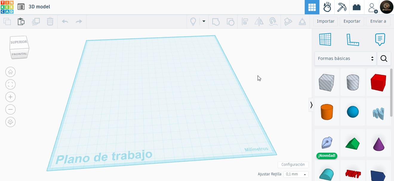
This week, I decided to keep the individual work simple and used Tinkercad, a very versatile tool that lets you design basic models in a short time.
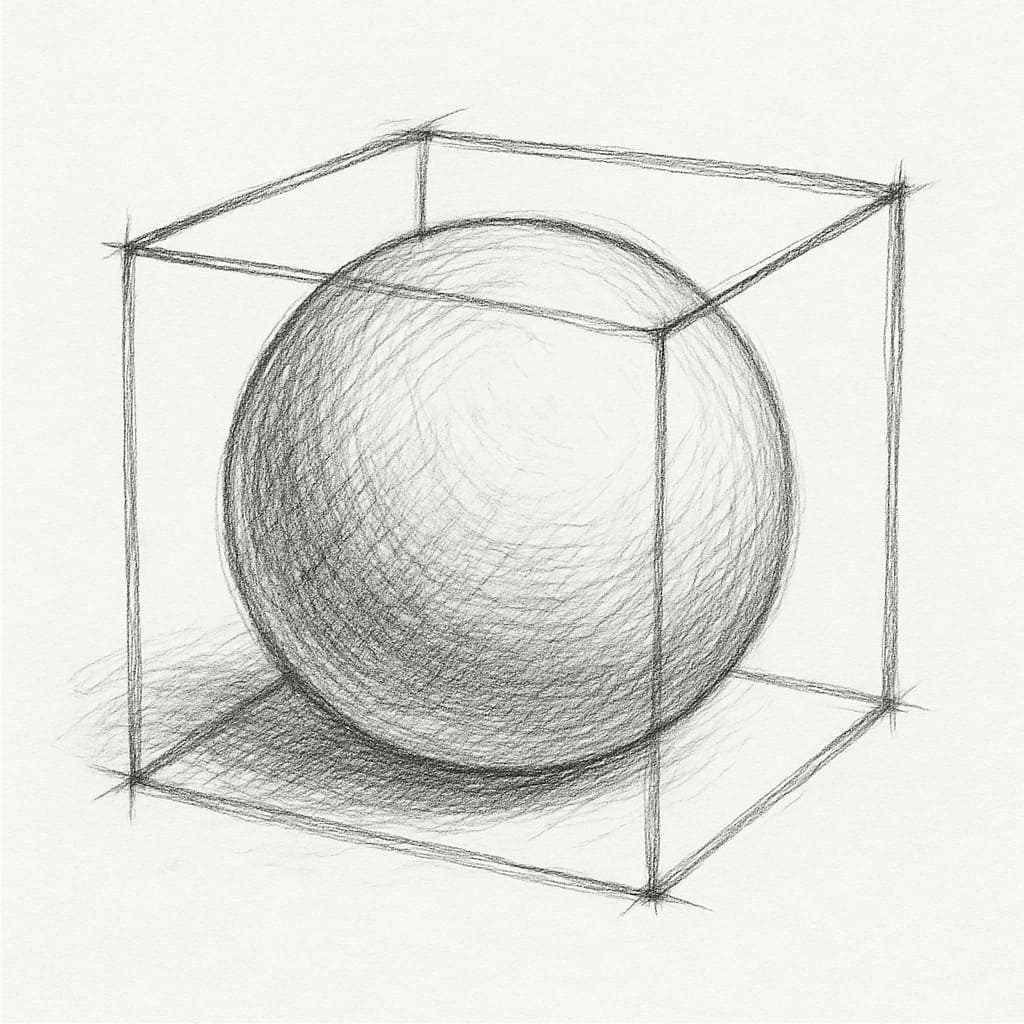
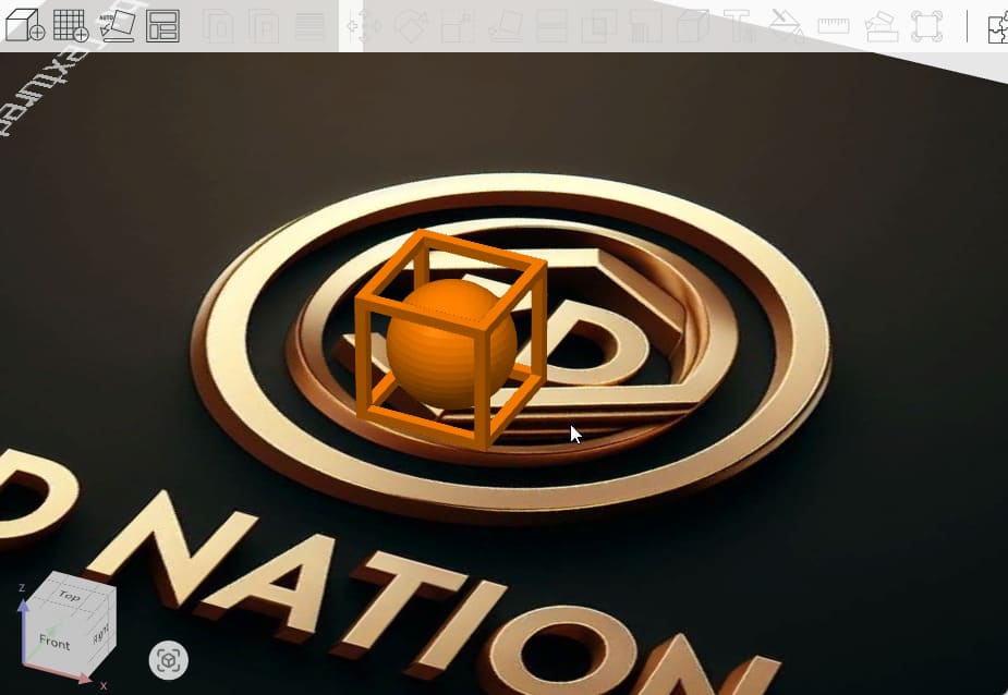
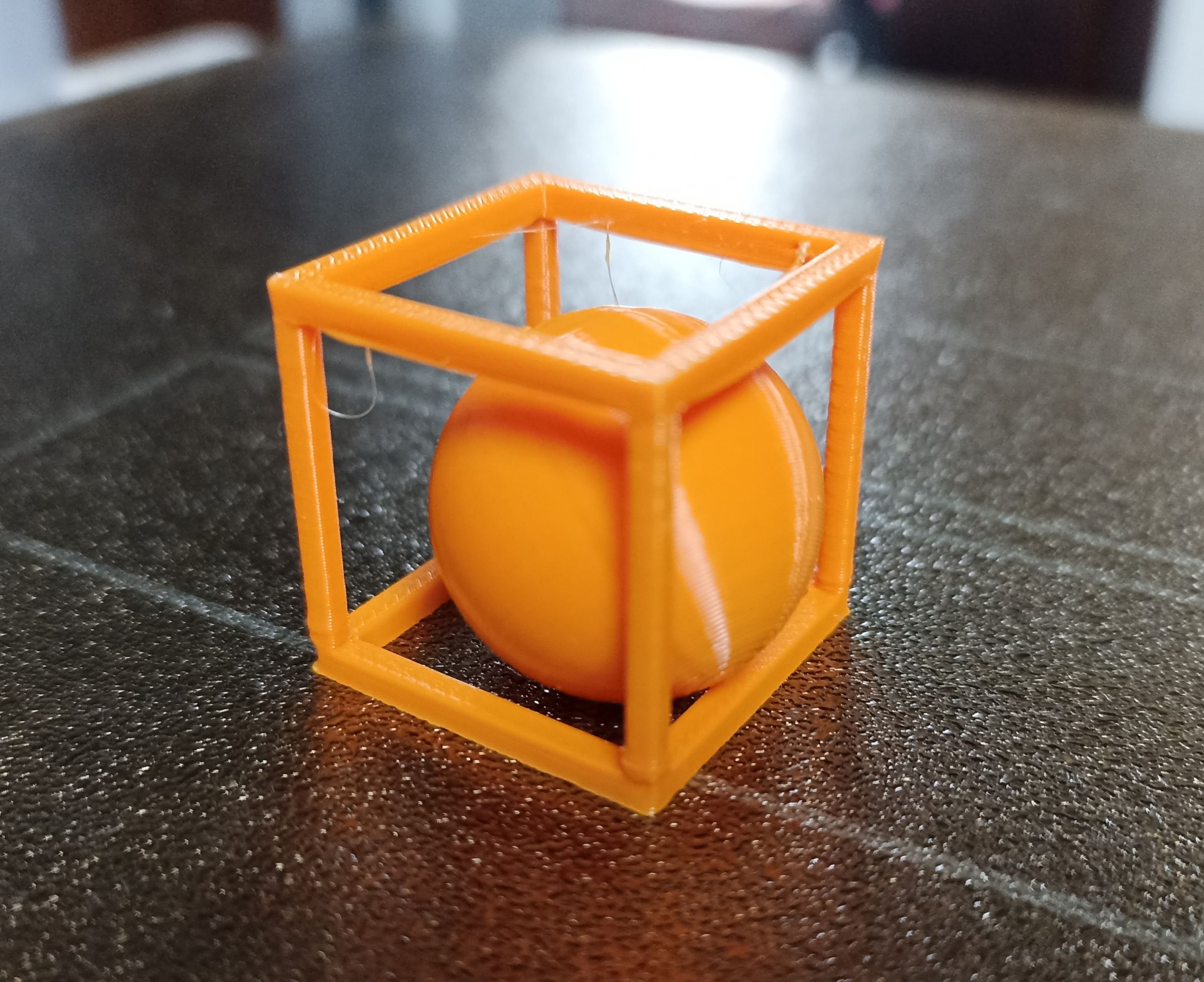
In the past, I tried to create an object inside another using traditional methods, but it was nearly impossible. With 3D printing, this is achievable. I decided to design a cube with a sphere inside. I first created a conceptual sketch using AI to visualize the idea before starting the modeling.
2.2 Why Not Subtractive
The object I created — a sphere trapped inside a hollow cube — is an example of something that cannot be made subtractively. Subtractive manufacturing, like CNC milling or laser cutting, works by removing material from a solid block using tools. These tools need physical access to the area they’re removing material from. If there’s a part inside another (like the sphere inside my cube), there’s no way to insert a cutting tool to shape the internal object without first cutting through the outer one.
Additionally, subtractive machines can’t cut or carve freely in all directions. They’re limited by the shape and reach of the tool, and by the rigidity of the stock material. Internal voids or enclosed objects are especially problematic. In contrast, 3D printing builds the model layer by layer from the bottom up, so internal features like the floating sphere can be created as the print progresses. This makes additive manufacturing ideal for creating objects with enclosed geometry, overhangs, internal channels, or moving parts trapped inside others.
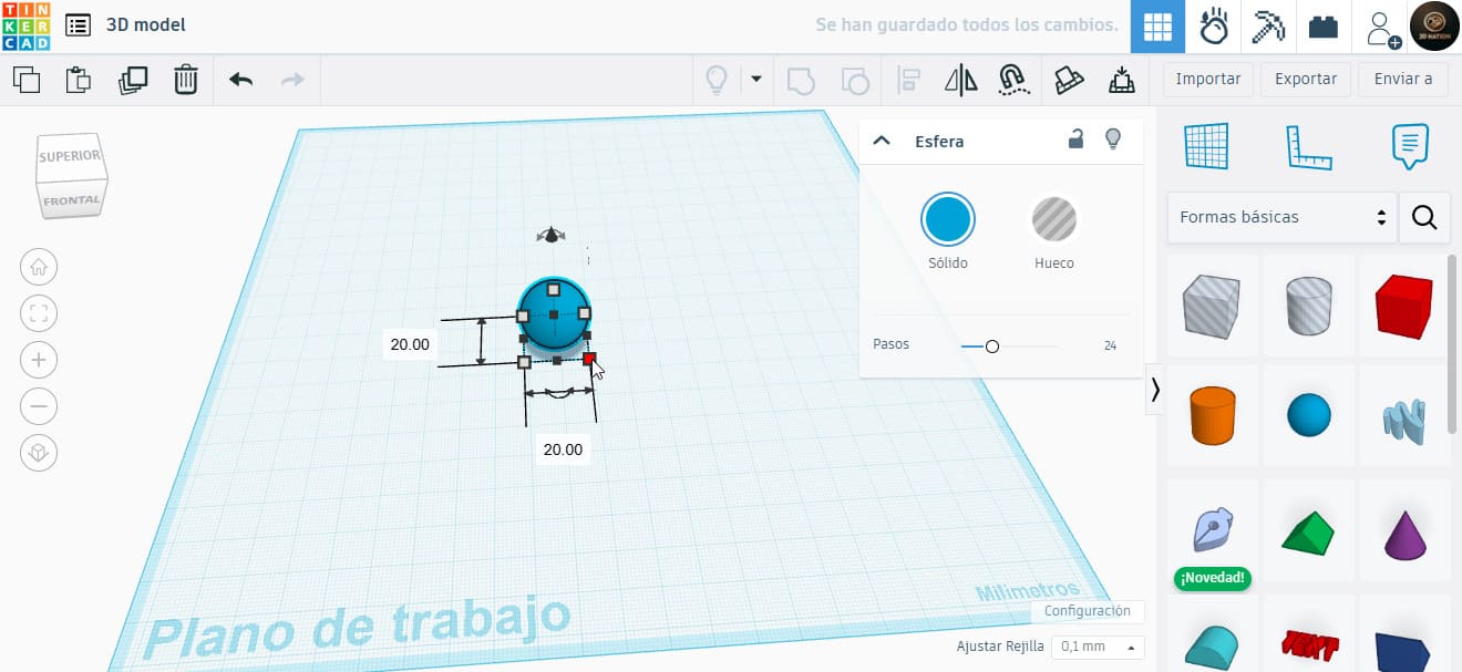
To begin in Tinkercad, I dragged a sphere into the workspace and left it at the standard size of 20x20x20 mm, as I hadn’t yet decided on the cube dimensions.
Next, I added a cube and made it 4 mm larger than the sphere in every dimension, making the edges 2 mm thick. I began adding rectangular shapes to create holes through each axis of the cube, aligned at 20 mm spacing.
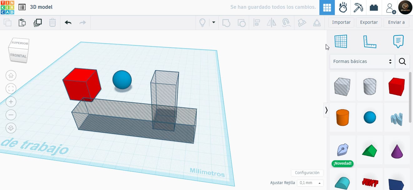
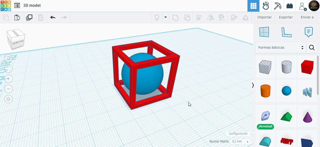
Using Tinkercad’s Boolean functions and the alignment tool, I set the rectangles to “hole” mode so they’d be subtracted from the cube. After repeating the process for all sides, I achieved the desired hollow cube.
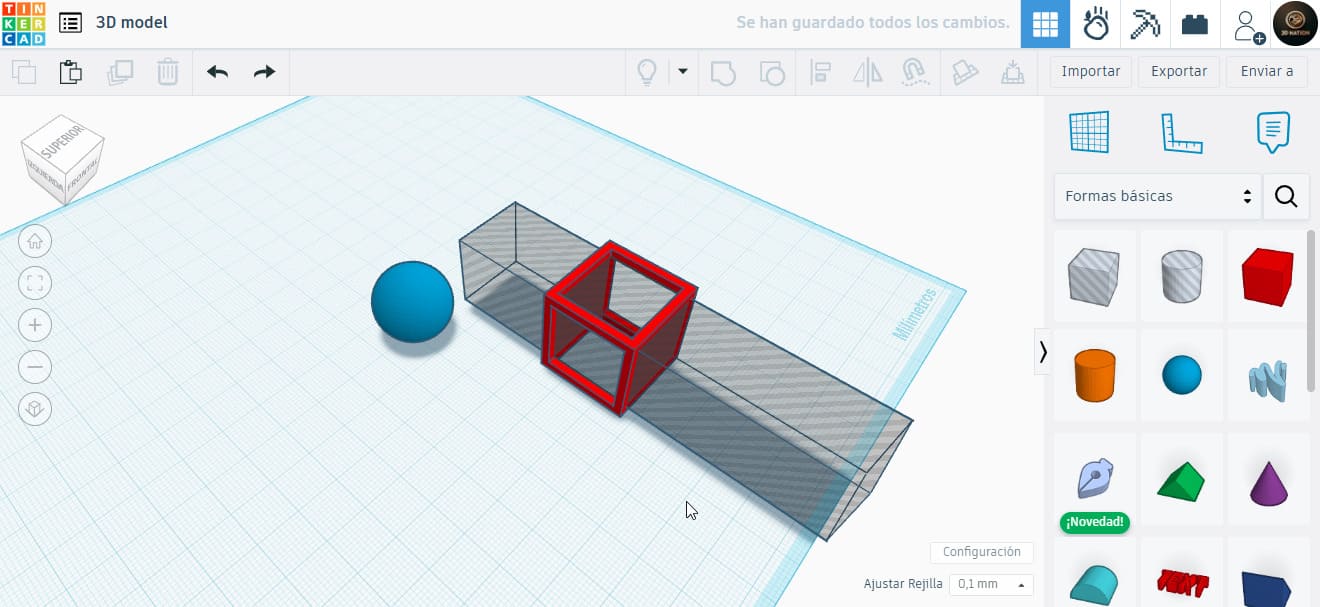
Later I realized the original 20 mm sphere was too small, and it might fall through the openings. So, I scaled it up to 23 mm in all directions. This way, the sphere would remain inside but still be smaller than the cube’s interior.
2.3 Slicing and Printing
Once the design was ready, I exported the model in STL format and used the Bambu Studio software for slicing. I used the standard 0.2 mm profile and selected the BambuLab A1 printer, which is fast and well-calibrated.
I chose a bright orange PLA filament. The slicer estimated a print time of 26 minutes, so I let the machine run.
I was concerned about the bridges since I printed without supports. Based on previous group tests, bridges up to 20 mm were manageable, but I kept a close eye on the print at that stage.
After completion, I removed the print carefully. The walls seemed thin, and I didn’t want to break the piece. This is something I could improve in a second iteration.
2.4 Observations and Results
After reviewing the piece, I noticed a slight artifact in the vertical edges. It appears to be caused by a change in speed between the bottom layer and the vertical walls.
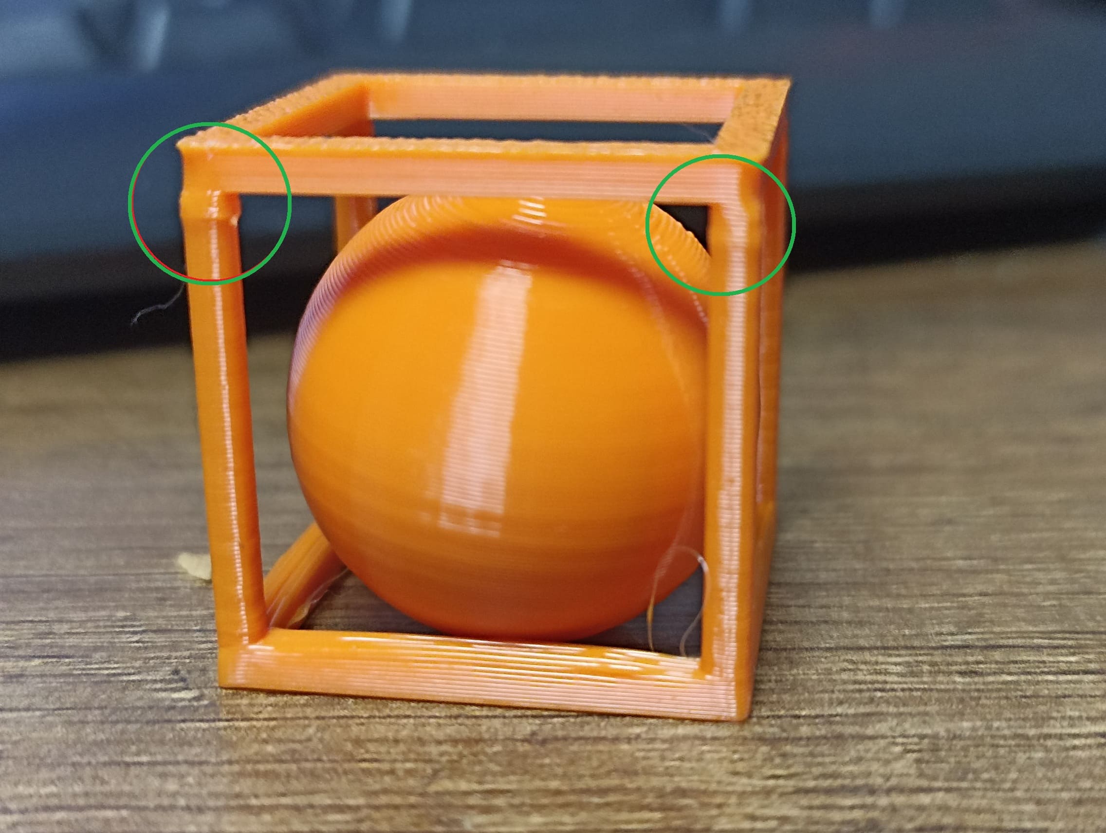
Despite these minor issues, the final result matched my expectations.
2.5 Advantages and Limitations
One of the biggest advantages of 3D printing is that it allows you to create very complex shapes that would be impossible or too expensive with traditional manufacturing. You can design internal structures, organic curves, custom parts, and iterate quickly with low cost. It’s especially useful for prototypes, low-volume production, or personalized items.
But 3D printing also has clear limitations. For example:
- It’s slower than other manufacturing methods when producing large quantities.
- Parts can be weak along the layer lines — strength depends on print orientation and material.
- Overhangs, bridges, and unsupported structures often need supports, which can leave marks or fail entirely.
- Surface finish isn’t always smooth unless post-processing is applied.
- Prints can fail due to issues like bed adhesion, under-extrusion, or temperature fluctuations.
In addition, 3D printing might not be suitable for:
- Objects requiring high precision or mechanical strength under stress.
- Parts exposed to high temperatures or industrial use unless using advanced materials like PEEK or Nylon CF.
- Very large items (unless you have specialized equipment).
- Mass production — injection molding or casting would be more efficient.
In short, 3D printing is powerful and flexible, but it’s not a one-size-fits-all solution. Understanding when and how to use it is just as important as knowing how to operate the machine.
3). 3D Scanning Workflow
3D scanning has always seemed more complex to me, but this week I followed a structured approach to make it easier:
- Decide what to scan
- Use a reference or concept tool
- (Optionally) print a sample
- Scan using Revopoint POP 2
- Print with resin for detail
Following this route, I wanted to try something complex. Though I know iPhones/iPads can scan objects using built-in sensors, their results vary.
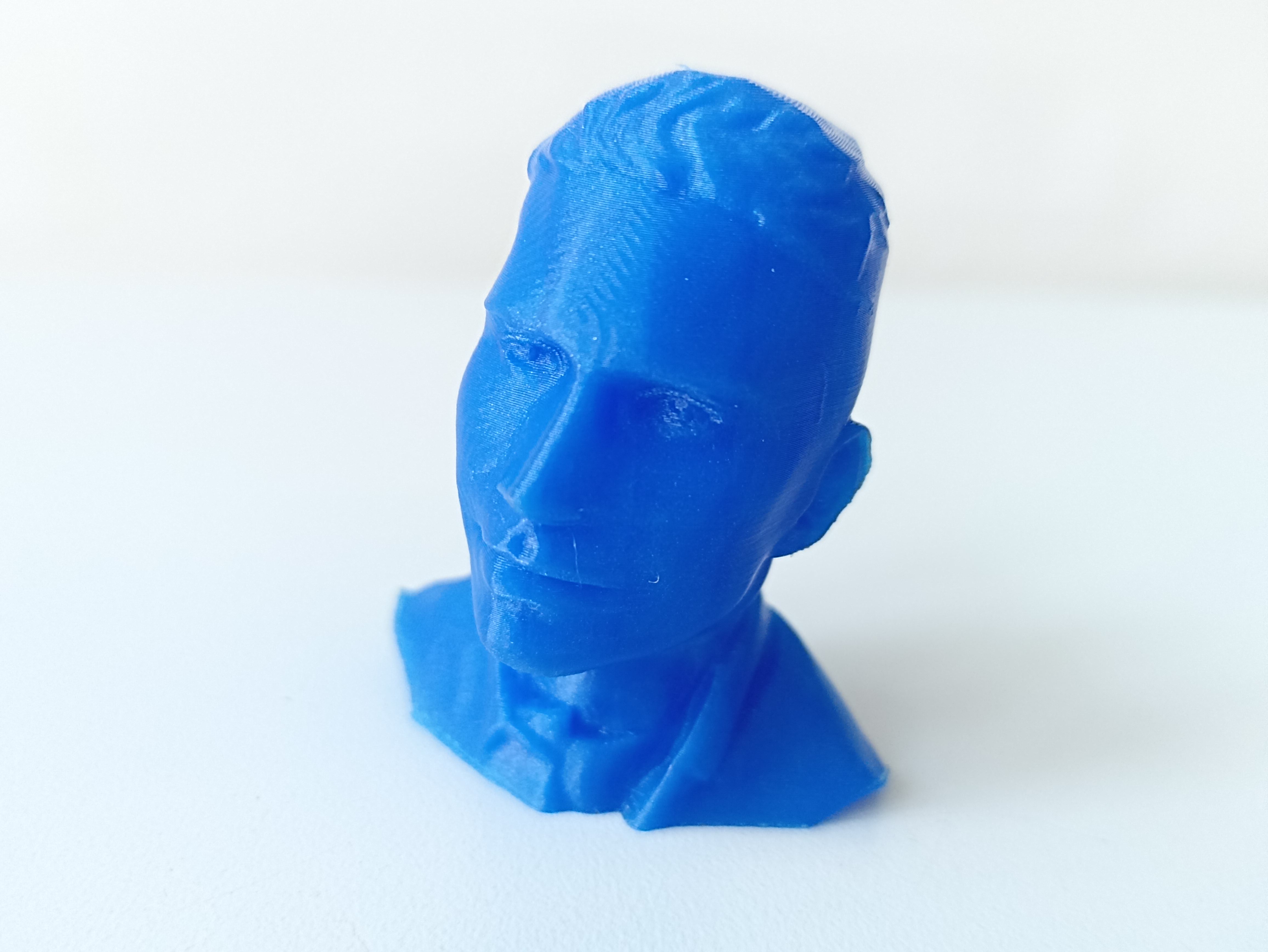
3.1 MakerWorld Bust Generator
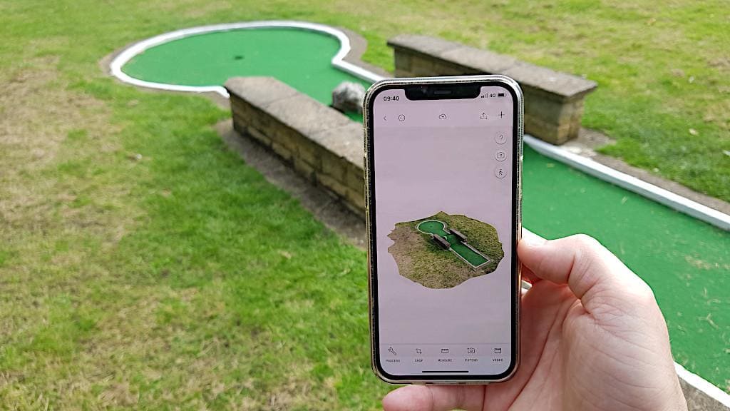
Instead, I wanted to try a larger scanner, so I attempted to scan a bust. Since scanning myself is tricky, I discovered a tool on MakerWorld that creates busts from a single image.
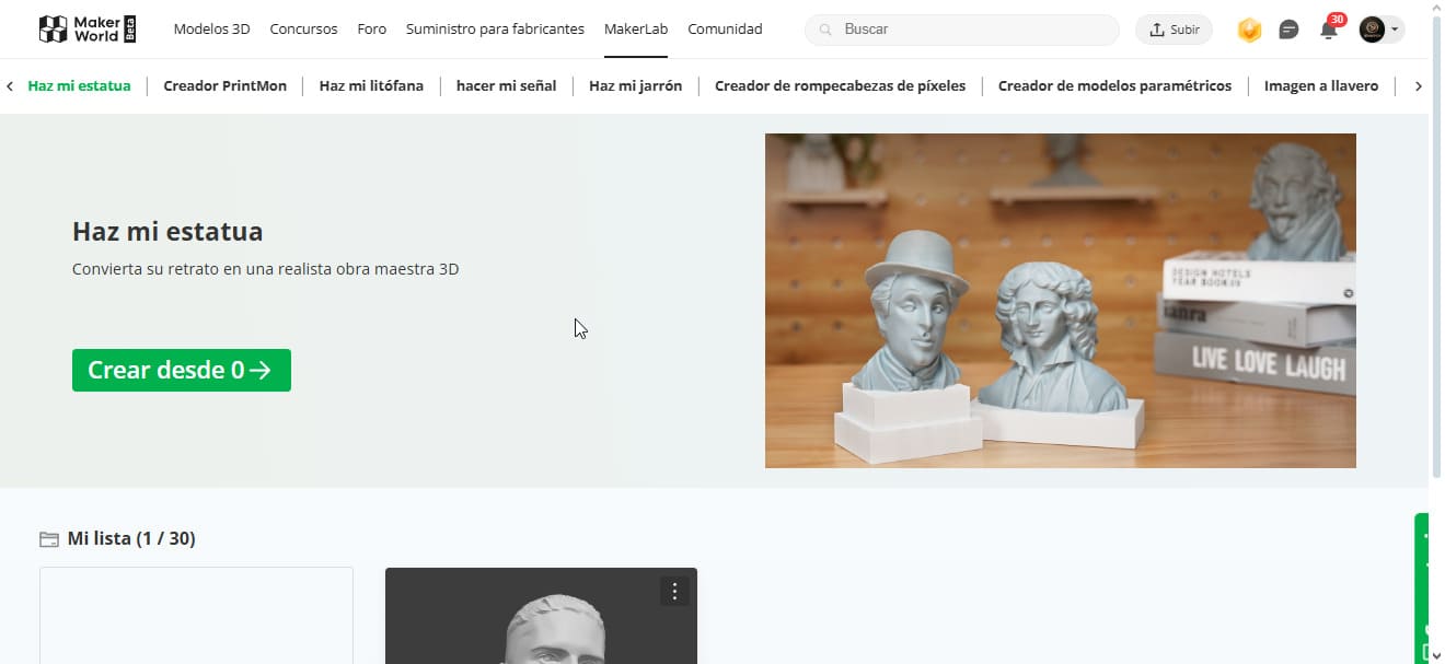
I uploaded a personal photo, and after a short processing time, the tool generated a 3D model. While it can't perceive depth like a real scanner, the result was impressive.
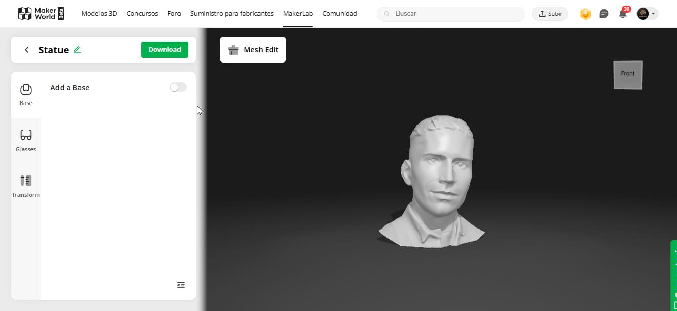
I liked the result so much that I printed it using the Elegoo Neptune 4 Pro at a high resolution of 0.08 mm layer height. The result was amazing.

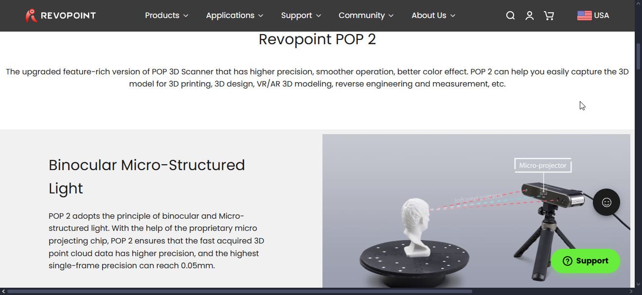
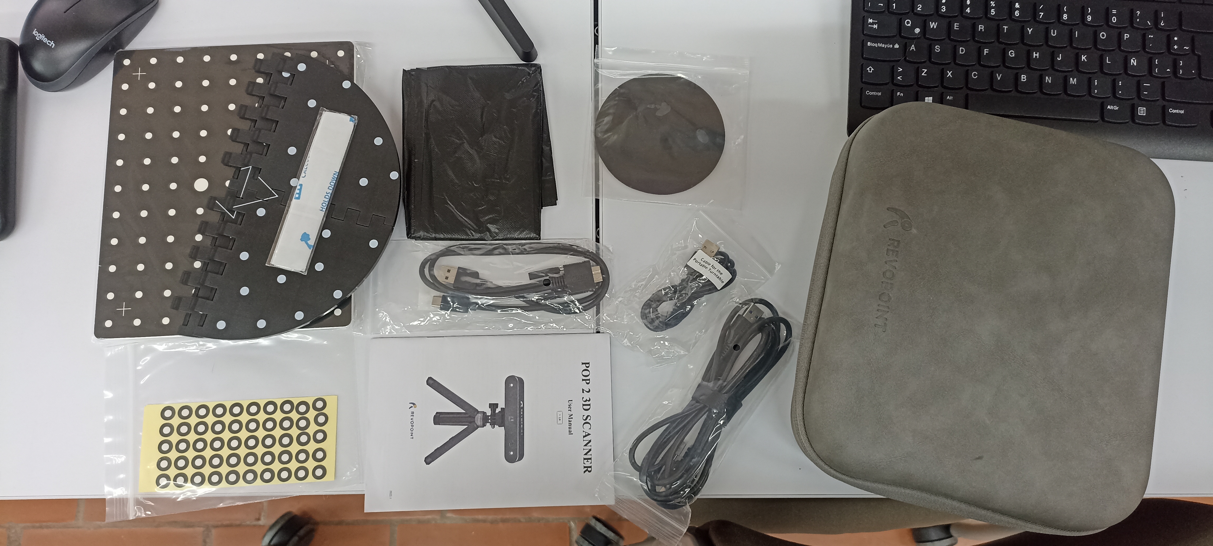
3.2 Using the Revopoint POP 2
For the real 3D scanning process, I used the Revopoint POP 2, a structured
light 3D scanner known for being lightweight, portable, and surprisingly accurate for small
to medium objects—even people.
I decided to scan one of my teammates as a test. Since I wanted the best possible quality, I
used a PC setup instead of mobile. The PC offers better performance, more
control over the scanning parameters, and a more stable connection. The scanner was
connected via USB.
The software used was Revo Scan 5, which comes with the Revopoint scanner.
It's easy to use and lets you see the 3D mesh in real-time while scanning. Before starting,
I adjusted basic settings like exposure, gain, and brightness to improve
point cloud detection.
I also enabled Feature Tracking, which helps the scanner follow natural
shapes and edges—perfect for scanning a human head.
One of the challenges we expected was scanning dark clothing or hair. The manual says it may not capture well, but we tried anyway. We made sure the room had soft, indirect lighting to avoid shadows or reflections. Surprisingly, the scanner did a great job capturing most surfaces.

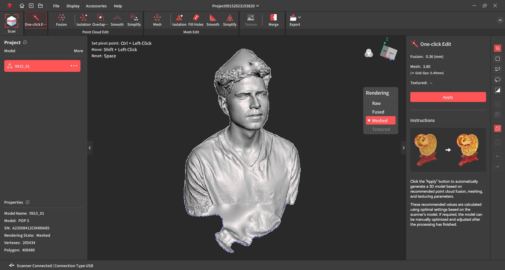
After finishing the scan, I used the Revo Scan 5 built-in tools to clean noise, fill holes, and smooth the surface. It’s a simple process that doesn’t require extra software. I exported the model as an STL to get it ready for 3D printing.
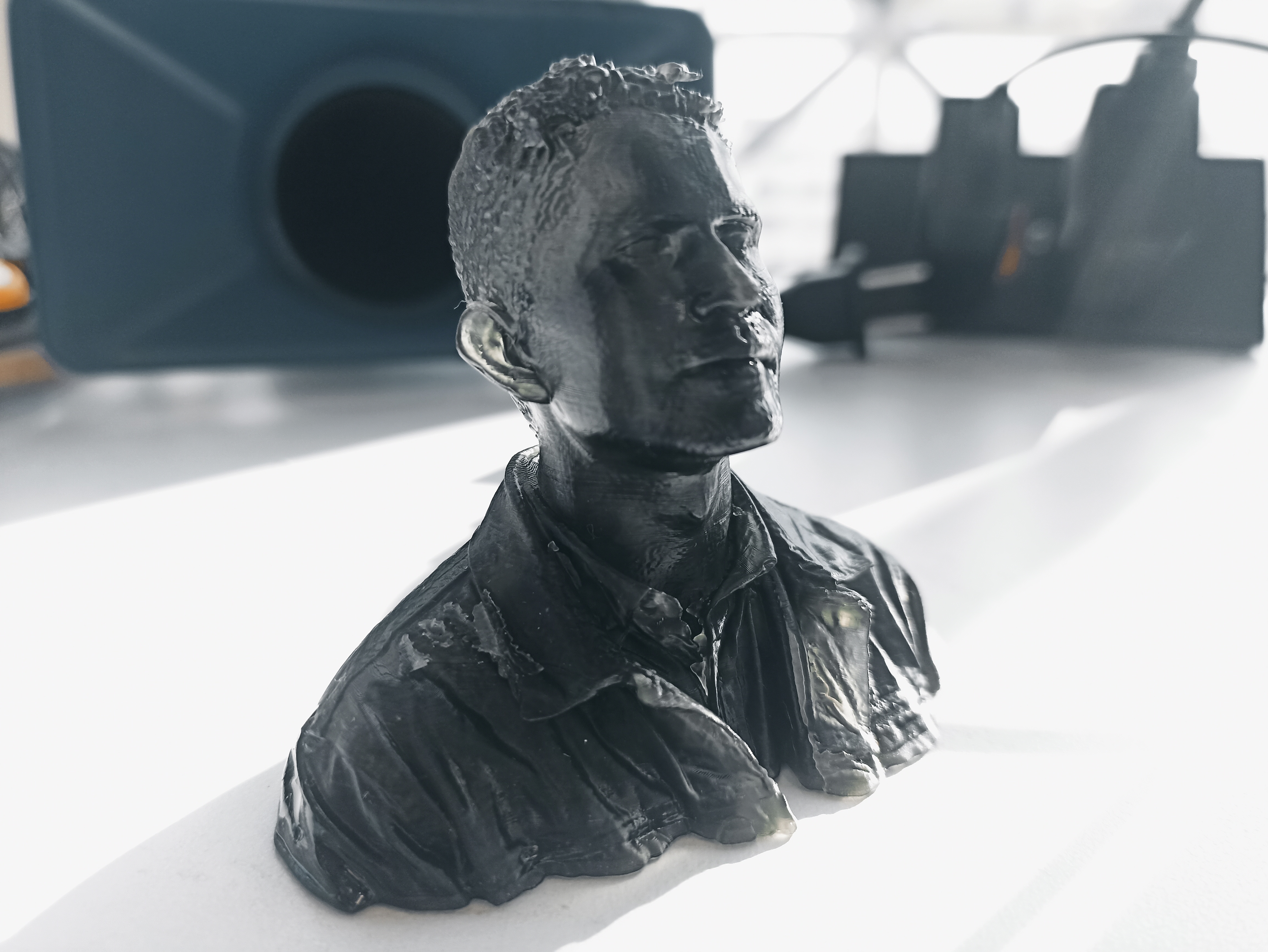
First, I printed the model in PLA filament to test the basic form. The result was good, but lacked facial detail. So I printed the same model again, this time using resin and finer layer height. The difference was huge—details like the nose, ears, and hair volume were much sharper.
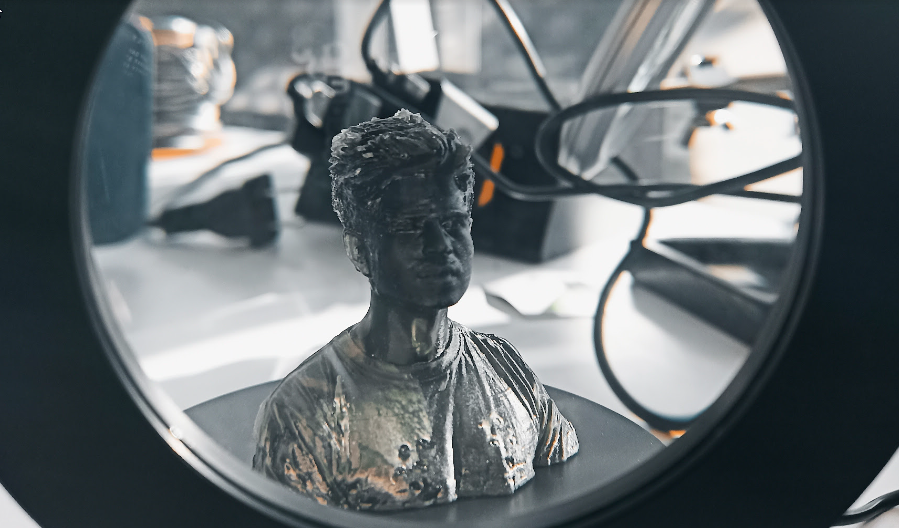
3.3 My 3D Scan
While helping my teammate, I got excited and decided to scan myself too. Since I couldn’t do
it alone, I asked him to return the favor. We used the same setup and scanning technique,
only changing the subject—me!
Thanks to what I had learned earlier, we knew exactly how to set the camera distance, adjust
light, and move slowly around the head to avoid gaps or misalignments.
After exporting the STL of my scan, I directly printed it in resin. This time, I fine-tuned the exposure time, layer height, and anti-aliasing in the slicer to make it even better. The result really surprised me—it looked like a mini statue of me!
And finally, I had to take a photo with my 3D-printed version. This process taught me that even with entry-level equipment, it's possible to get professional results if you understand lighting, software settings, and scanning rhythm.
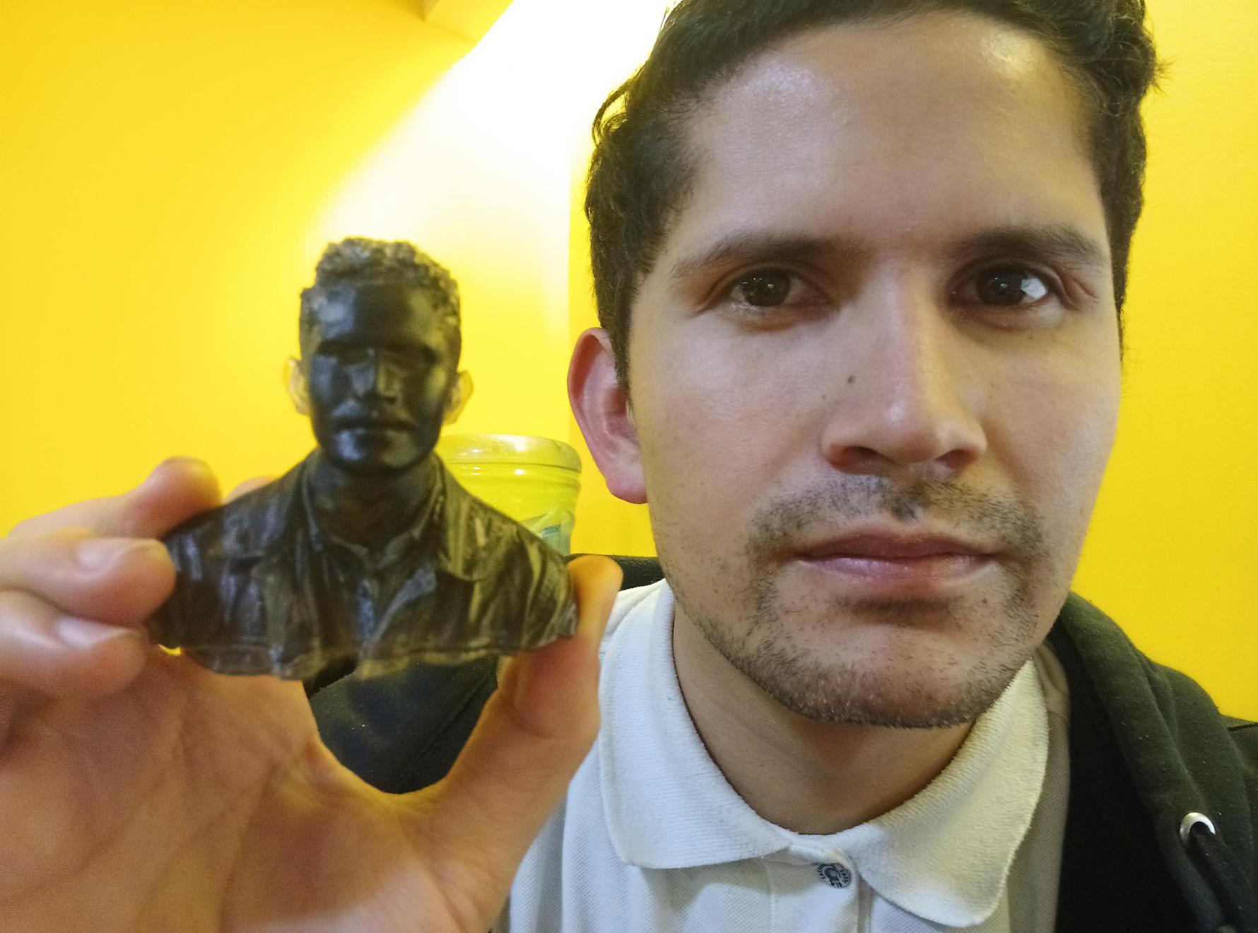
Scanning, cleaning, and printing my own 3D model was not only fun—it also helped me appreciate how accessible and creative digital fabrication has become. I’m already thinking about more scans to try!
Conclusions
Personal conclusions from this week
This week was one of my favorites, as I’m very passionate about 3D printing and own several machines. The modeling part was straightforward thanks to my previous experience. However, I’d like to improve the aesthetics of future models, especially wall thickness and overhang strength.
Regarding scanning, I’m amazed at how AI tools are evolving to generate 3D geometry from simple images. Still, dedicated 3D scanners like Revopoint offer unmatched detail and performance. Mastering this tool took me weeks back when I first started, but now I was able to get results on my first attempt.
Even though the print was mostly successful, it wasn't perfect. The bridges and corners of the cube showed slight artifacts, and some vertical lines had surface irregularities. These issues could be improved by adjusting print speed, retraction settings, or wall thickness in future versions.
I also learned that certain shapes require careful consideration of slicer parameters — especially when printing without supports. For more consistent results, I’d recommend using more rigid materials and avoiding overly thin features.
This assignment reminded me that digital fabrication is a mix of software, hardware, and experience. Every small change — in the model, the filament, or the printer — can affect the final outcome. But that’s what makes this process so exciting: you learn something new every time you hit "print".
Downloads
3D Models
Extra Models – Shared via FabLab EAN Drive
These files are hosted on the official FabLab EAN Drive due to their larger size: