Assignments
Group Assignment:
- Compare as many tool options as possible.
- Document your work on the group work page and reflect on your individual page what
you learned.
Individual Assignment:
- Write an application for the embedded board that you made, that interfaces a user
with an input and/or output device(s).
Week 14. interface and application programming
Reflection on Group Work and Personal Learning
This was one of the most enriching group assignments so far. Working together allowed us to explore various ways in which user interfaces can be implemented within embedded systems. More than just dividing tasks, we took the time to share experiences, show results, and explain how each tool worked — which greatly expanded my understanding.
Throughout our sessions, I was introduced to interface development tools that I had never used before, such as PyQt5 for desktop applications, MIT App Inventor and Kodular for mobile apps, and Processing for serial data visualization. It was fascinating to see how each of these platforms can turn raw sensor data into readable, interactive formats for users.
One of the most surprising insights came from seeing a teammate's project that used Oculus and virtual reality to build a fully immersive interface. This pushed the boundaries of what I thought was possible in embedded systems and reminded me that interaction design is not just about screens and buttons — it can also be spatial and experiential.
What I valued the most was understanding how different tools adapt to different needs. While some platforms are ideal for mobile or quick deployment, others allow deeper customization or visual polish. By learning from my peers’ approaches, I now feel better equipped to evaluate which interface tool fits best depending on the type of project and user.
In conclusion, this assignment strengthened not only my technical skills but also my appreciation for collaborative learning. Interfaces are more than just visual layers — they’re bridges between people and machines. And building those bridges becomes much more effective when we learn from others’ perspectives and experiences.
1). Introduction
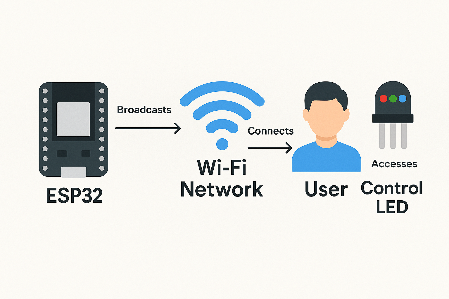
This week, I wanted to explore a different kind of interface — one that would allow me to interact with my board through a browser, without needing cables, external software, or mobile apps. For that reason, I decided to create a local web interface using HTML hosted directly on the ESP32-S3 through its Access Point (AP) mode.
This approach lets the microcontroller generate its own Wi-Fi network. Any user who connects to it can access a simple web page served by the ESP32 itself. I saw this method as a practical and scalable solution — especially because it allows for remote control without reprogramming the board. This could be incredibly useful in my final project or any future systems that require remote management or user feedback.
My main goal was to control output elements, such as an RGB LED, directly from this web interface. I reused the custom PCB designed in Week 8, which already includes soldered pins for the LED, simplifying integration. Combining Arduino code with embedded HTML gave me a lot of creative freedom and opened new perspectives for user interaction in embedded systems.
2). System Overview
The system developed this week is designed to demonstrate how a microcontroller can generate its own wireless network and serve an interactive HTML interface without relying on external servers or internet access. This type of configuration is ideal for creating simple, offline user interfaces for embedded systems, especially when direct interaction is required.
For this exercise, I reused my custom ESP32-S3 PCB designed and manufactured in Week 8. The board includes all the necessary wiring and soldered headers to support the RGB LED output and touch sensor input. The LED used is a common cathode RGB module, meaning each color line is active HIGH and controlled individually.
The ESP32-S3 is configured to operate in Access Point mode (AP), broadcasting a local Wi-Fi network with a fixed IP and password. Once connected, any user can access the ESP’s web interface through a browser, where they can turn the RGB LED on or off, or activate a random color effect using simple buttons.
| Component | Description |
|---|---|
| Microcontroller | ESP32-S3 (on custom PCB from Week 8) |
| Output Device | RGB LED module – common cathode |
| Pin Mapping | Red: GPIO 5, Green: GPIO 4, Blue: GPIO 6 |
| Touch Sensor (optional) | Capacitive sensor – connected to GPIO 2 (future use) |
| Network Mode | Wi-Fi Access Point (AP) generated by ESP32-S3 |
| Access Details | SSID: ESP32-AP / Password: 12345678 /
IP:
192.168.4.1
|
The diagram below summarizes how the interface works: the ESP32 broadcasts a Wi-Fi network, the user connects to it, and then accesses a control panel served directly by the microcontroller to trigger LED behaviors.
3). UI Design
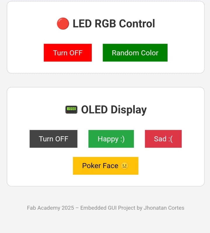
For this assignment, I created a basic yet functional web interface entirely using HTML, CSS, and minimal inline JavaScript logic. The interface is served directly from the ESP32-S3 through an Access Point (AP) mode configuration, meaning no internet connection is needed. The board acts as both the host and server.
The design was kept clean and responsive, optimized for use from a smartphone or browser. It features three buttons to control the RGB LED connected to the board:
- ON: Turns on all three LED colors (White).
- OFF: Turns off the LED completely.
- Random Color: Sets a random combination of RGB values.
Styling was applied with internal CSS rules to make the layout more
user-friendly
and distinguishable
through color-coded buttons. Since it is embedded directly in the Arduino sketch
using the PROGMEM
keyword, no external file storage (like SPIFFS) was needed. This keeps the
system
simple and self-contained.
Below is a screenshot of how the interface looks when accessed through a browser while connected to the ESP32's Wi-Fi network:
This HTML interface was defined within a string inside the Arduino code, and
dynamically served via the
WebServer library. Each button sends an HTTP GET request to a
specific
route, which the
microcontroller interprets and executes accordingly.
4). Communication Workflow
The communication between the web interface and the ESP32-S3 is established
using
HTTP GET requests.
When the ESP32 is in Access Point (AP) mode, it creates a Wi-Fi
network that the user can connect to directly.
Once connected, the browser accesses the ESP32’s fixed IP address (e.g.,
192.168.4.1) and loads the HTML interface.
Each button in the interface is linked to a unique route on the ESP32:
/– Loads the HTML page with the control buttons./on– Turns the RGB LED fully ON (White – all colors activated)./off– Turns the RGB LED OFF./random– Generates a random RGB color.
WebServer library, which maps each
route
to a corresponding function in the code.
The server responds to the browser with a redirect back to the root page after
executing
the action.
Since this is a simple one-way control interface, no AJAX or JavaScript parsing is needed—everything is handled via direct page requests. This makes it lightweight and ideal for fast microcontroller-based projects that don’t require persistent server-client state.
Here is a simplified flow of how the system communicates:
- 1. User connects to ESP32-AP Wi-Fi network.
- 2. User enters
192.168.4.1in the browser. - 3. Interface is served by ESP32 (HTML + CSS).
- 4. User clicks a button → Browser sends GET request to ESP32.
- 5. ESP32 executes action and responds with a
redirect to
/.
This simple but effective method makes it easy to create standalone, offline control systems where a mobile device can interact directly with a microcontroller over Wi-Fi without needing any additional infrastructure or cloud services.
5). Programming
The code for this project was written in the Arduino IDE using a set of essential libraries to enable Wi-Fi, web server functionality, and OLED screen control:
<WiFi.h>: To create a Wi-Fi Access Point (AP).<WebServer.h>: To serve HTTP requests and create REST-like endpoints.<Adafruit_GFX.h>and<Adafruit_SSD1306.h>: For controlling the OLED screen.
The ESP32-S3 creates a local network named ESP32-AP with password
12345678. Once connected, users access the
interface via their browser at the IP address 192.168.4.1.
The HTML interface is embedded directly in the code using a raw literal string, so no external files or SPIFFS are needed. The interface includes buttons for LED control and OLED display options.
Each button sends a GET request to the ESP32 using JavaScript's
fetch()
function. The ESP receives the request and executes
the associated function, such as turning off the LED or displaying a face on the
screen.
// Required libraries
#include <WiFi.h>
#include <WebServer.h>
#include <Adafruit_GFX.h>
#include <Adafruit_SSD1306.h>


#define SCREEN_WIDTH 128
#define SCREEN_HEIGHT 64
#define OLED_RESET    -1
#define SCREEN_ADDRESS 0x3C
Adafruit_SSD1306 display(SCREEN_WIDTH, SCREEN_HEIGHT, &Wire, OLED_RESET);

#define RED_PIN    4
#define GREEN_PIN  5
#define BLUE_PIN   6
#define BUZZER_PIN 19

const char* ssid = "ESP32-AP";
const char* password = "12345678";
WebServer server(80);

// ======================= HTML ========================

const char* html = R"rawliteral(
<!DOCTYPE html>
<html>
<head>
  <meta charset="UTF-8">
  <title>SAFETY CONTROL PANEL</title>
  <style>
    body {
      font-family: sans-serif;
      background-color: #f4f4f4;
      color: #333;
      padding: 20px;
      text-align: center;
    }
    section {
      margin-bottom: 30px;
      padding: 15px;
      border: 1px solid #ccc;
      border-radius: 10px;
      background: #fff;
      max-width: 400px;
      margin-left: auto;
      margin-right: auto;
    }
    button {
      padding:10px 20px;
      border:none;
      margin: 10px;
      font-size: 16px;
      cursor: pointer;
    }
  </style>
  <script>
    function sendCommand(endpoint) {
      fetch(endpoint).then(r => r.text()).then(console.log);
    }
  </script>
</head>
<body>
  <h1>🛠️ Fabsafe Interface</h1>

  <section>
    <h2>🔴 LED RGB Control</h2>
    <button onclick="sendCommand('/led/off')" style="background:red; color:white;">Turn OFF</button>
    <button onclick="sendCommand('/led/random')" style="background:green; color:white;">Random Color</button>
  </section>

  <section>
    <h2>📟 OLED Display</h2>
    <button onclick="sendCommand('/oled/off')" style="background:#444; color:white;">Turn OFF</button>
    <button onclick="sendCommand('/oled/happy')" style="background:#28a745; color:white;">Happy :)</button>
    <button onclick="sendCommand('/oled/sad')" style="background:#dc3545; color:white;">Sad :(</button>
    <button onclick="sendCommand('/oled/poker')" style="background:#ffc107; color:black;">Poker Face 😐</button>
  </section>

  <footer style="font-size:12px; margin-top:40px; color:#888;">
    Fab Academy 2025 – Embedded GUI Project by Jhonatan Cortes
  </footer>
</body>
</html>
)rawliteral";


// ================ FUNCIONES DE SERVIDOR ==================
void handleRoot() { server.send(200, "text/html", html); }

void handleLedOff() {
  analogWrite(RED_PIN, 255);
  analogWrite(GREEN_PIN, 255);
  analogWrite(BLUE_PIN, 255);
  server.send(200, "text/plain", "LED apagado");
}

void handleLedRandom() {
  analogWrite(RED_PIN, 255 - random(0, 256));
  analogWrite(GREEN_PIN, 255 - random(0, 256));
  analogWrite(BLUE_PIN, 255 - random(0, 256));
  tone(BUZZER_PIN, 1500, 100);
  server.send(200, "text/plain", "Color aleatorio");
}

void handleOledOff() {
  display.clearDisplay();
  display.display();
  server.send(200, "text/plain", "Pantalla apagada");
}

void handleOledHappy() {
  display.clearDisplay();
  display.setTextSize(3);
  display.setTextColor(WHITE);
  display.setCursor(40, 0);
  display.print(":)");
  display.setTextSize(1);
  display.setCursor(0, 50);
  display.print("Modo: FELIZ");
  display.display();
  server.send(200, "text/plain", "Feliz");
}

void handleOledSad() {
  display.clearDisplay();
  display.setTextSize(3);
  display.setTextColor(WHITE);
  display.setCursor(40, 0);
  display.print(":(");
  display.setTextSize(1);
  display.setCursor(0, 50);
  display.print("Modo: TRISTE");
  display.display();
  server.send(200, "text/plain", "Triste");
}

void handleOledPoker() {
  display.clearDisplay();
  display.setTextSize(3);
  display.setTextColor(WHITE);
  display.setCursor(25, 0);
  display.print(":|");
  display.setTextSize(1);
  display.setCursor(0, 50);
  display.print("Modo: POKER FACE");
  display.display();
  server.send(200, "text/plain", "Poker face");
}

void setup() {
  Serial.begin(115200);
  WiFi.softAP(ssid, password);
  Serial.println(WiFi.softAPIP());

  pinMode(RED_PIN, OUTPUT);
  pinMode(GREEN_PIN, OUTPUT);
  pinMode(BLUE_PIN, OUTPUT);
  pinMode(BUZZER_PIN, OUTPUT);

  // OLED
  Wire.begin(21, 20);  // SDA = 21, SCL = 20
  if (!display.begin(SSD1306_SWITCHCAPVCC, SCREEN_ADDRESS)) {
    Serial.println(F("Fallo pantalla OLED"));
    while (true);
  }
  display.clearDisplay();
  display.setTextSize(1);
  display.setTextColor(WHITE);
  display.setCursor(0, 0);
  display.print("Sistema listo");
  display.display();

  // Servidor
  server.on("/", handleRoot);
  server.on("/led/off", handleLedOff);
  server.on("/led/random", handleLedRandom);
  server.on("/oled/off", handleOledOff);
  server.on("/oled/happy", handleOledHappy);
  server.on("/oled/sad", handleOledSad);
  server.on("/oled/poker", handleOledPoker);
  server.begin();
}

void loop() {
  server.handleClient();
}
🌐 Embedded Interface Code Breakdown
In this section, I present the complete code for the web interface and system logic I implemented on the ESP32-S3. Everything — including the HTML, CSS, JavaScript, and C++ — is embedded directly in the Arduino sketch using a raw literal string and internal web server. I structured this project so that the interface would not require external files or an internet connection, only local interaction.
📄 HTML – Page Structure
Inside the html raw literal variable, I structured the web
page with two main sections: one to control the LED RGB and another for
the OLED display. There’s also a footer to identify the project.
<!DOCTYPE html>
<html>
<head>
  <meta charset="UTF-8">
  <title>SAFETY CONTROL PANEL</title>
  <style> ... </style>
  <script> ... </script>
</head>
<body>
  <h1>🛠️ Fabsafe Interface</h1>

  <section>
    <h2>🔴 LED RGB Control</h2>
    <button onclick="sendCommand('/led/off')" style="background:red; color:white;">Turn OFF</button>
    <button onclick="sendCommand('/led/random')" style="background:green; color:white;">Random Color</button>
  </section>

  <section>
    <h2>📟 OLED Display</h2>
    <button onclick="sendCommand('/oled/off')" style="background:#444; color:white;">Turn OFF</button>
    <button onclick="sendCommand('/oled/happy')" style="background:#28a745; color:white;">Happy :)</button>
    <button onclick="sendCommand('/oled/sad')" style="background:#dc3545; color:white;">Sad :(</button>
    <button onclick="sendCommand('/oled/poker')" style="background:#ffc107; color:black;">Poker Face 😐</button>
  </section>

  <footer style="font-size:12px; margin-top:40px; color:#888;">
    Fab Academy 2025 – Embedded GUI Project by Jhonatan Cortes
  </footer>
</body>
</html>
🎨 CSS – Styling (Inline)
I embedded the CSS inside a <style> tag directly in
the <head> of the HTML. It defines the general
layout, fonts, background color, and button style.
body {
  font-family: sans-serif;
  background-color: #f4f4f4;
  color: #333;
  padding: 20px;
  text-align: center;
}

section {
  margin-bottom: 30px;
  padding: 15px;
  border: 1px solid #ccc;
  border-radius: 10px;
  background: #fff;
  max-width: 400px;
  margin-left: auto;
  margin-right: auto;
}

button {
  padding:10px 20px;
  border:none;
  margin: 10px;
  font-size: 16px;
  cursor: pointer;
}
⚙️ JavaScript – Button Command Logic
This simple script listens for button clicks and sends an HTTP request
to the ESP32-S3 through fetch().
It’s embedded in a <script> tag in the HTML header.
function sendCommand(endpoint) {
  fetch(endpoint)
    .then(r => r.text())
    .then(console.log);
}
🔧 Arduino Code – Server Setup and Initialization
After writing the HTML interface, I configured the ESP32-S3 as a Wi-Fi Access Point. I also initialized the OLED display using the Adafruit library and configured all the I/O pins. Then I mapped HTTP routes to functions that control the LED, buzzer and display.
#include <WiFi.h>
#include <WebServer.h>
#include <Adafruit_GFX.h>
#include <Adafruit_SSD1306.h>

#define SCREEN_WIDTH 128
#define SCREEN_HEIGHT 64
#define OLED_RESET -1
#define SCREEN_ADDRESS 0x3C
Adafruit_SSD1306 display(SCREEN_WIDTH, SCREEN_HEIGHT, &Wire, OLED_RESET);

#define RED_PIN 4
#define GREEN_PIN 5
#define BLUE_PIN 6
#define BUZZER_PIN 19

const char* ssid = "ESP32-AP";
const char* password = "12345678";
WebServer server(80);

void setup() {
  Serial.begin(115200);
  WiFi.softAP(ssid, password);
  Serial.println(WiFi.softAPIP());

  pinMode(RED_PIN, OUTPUT);
  pinMode(GREEN_PIN, OUTPUT);
  pinMode(BLUE_PIN, OUTPUT);
  pinMode(BUZZER_PIN, OUTPUT);

  Wire.begin(21, 20); // SDA, SCL
  if (!display.begin(SSD1306_SWITCHCAPVCC, SCREEN_ADDRESS)) {
    Serial.println(F("Fallo pantalla OLED"));
    while (true);
  }

  display.clearDisplay();
  display.setTextSize(1);
  display.setTextColor(WHITE);
  display.setCursor(0, 0);
  display.print("Sistema listo");
  display.display();

  server.on("/", []() { server.send(200, "text/html", html); });
  server.on("/led/off", handleLedOff);
  server.on("/led/random", handleLedRandom);
  server.on("/oled/off", handleOledOff);
  server.on("/oled/happy", handleOledHappy);
  server.on("/oled/sad", handleOledSad);
  server.on("/oled/poker", handleOledPoker);
  server.begin();
}

void loop() {
  server.handleClient();
}
⚙️ Arduino Code – Route Functions
Each endpoint in the interface is linked to a function in the Arduino code. Below are the functions I wrote to handle the LED and OLED behaviors when each button is pressed.
void handleLedOff() {
  analogWrite(RED_PIN, 255);
  analogWrite(GREEN_PIN, 255);
  analogWrite(BLUE_PIN, 255);
  server.send(200, "text/plain", "LED apagado");
}

void handleLedRandom() {
  analogWrite(RED_PIN, 255 - random(0, 256));
  analogWrite(GREEN_PIN, 255 - random(0, 256));
  analogWrite(BLUE_PIN, 255 - random(0, 256));
  tone(BUZZER_PIN, 1500, 100);
  server.send(200, "text/plain", "Color aleatorio");
}

void handleOledOff() {
  display.clearDisplay();
  display.display();
  server.send(200, "text/plain", "Pantalla apagada");
}

void handleOledHappy() {
  display.clearDisplay();
  display.setTextSize(3);
  display.setTextColor(WHITE);
  display.setCursor(40, 0);
  display.print(":)");
  display.setTextSize(1);
  display.setCursor(0, 50);
  display.print("Modo: FELIZ");
  display.display();
  server.send(200, "text/plain", "Feliz");
}

void handleOledSad() {
  display.clearDisplay();
  display.setTextSize(3);
  display.setTextColor(WHITE);
  display.setCursor(40, 0);
  display.print(":(");
  display.setTextSize(1);
  display.setCursor(0, 50);
  display.print("Modo: TRISTE");
  display.display();
  server.send(200, "text/plain", "Triste");
}

void handleOledPoker() {
  display.clearDisplay();
  display.setTextSize(3);
  display.setTextColor(WHITE);
  display.setCursor(25, 0);
  display.print(":|");
  display.setTextSize(1);
  display.setCursor(0, 50);
  display.print("Modo: POKER FACE");
  display.display();
  server.send(200, "text/plain", "Poker face");
}
6). Functional Testing
After programming the ESP32-S3 and deploying the web interface, I successfully
connected to the network ESP32-AP
using the password 12345678. Then I accessed the interface via the
browser using the IP 192.168.4.1.
The following videos demonstrate how the web interface works in real time. One video shows the RGB LED turning on with random colors and off using the buttons. The second video shows the OLED display responding to button presses by showing happy, sad, and poker face expressions.
🎥 LED RGB Control Test
This video shows how the buttons on the web interface control the RGB LED in real time through Wi-Fi.
🎥 OLED Display Test
This video shows different face modes being displayed on the OLED, triggered by the buttons on the interface.
7). Troubleshooting & Solutions
This week, the assignment was surprisingly smooth. Creating a local Access Point
and
serving a web interface from the ESP32-S3 turned out to be more intuitive than
expected.
The WiFi.h and WebServer.h libraries worked
out-of-the-box
with no compatibility issues.
I didn't experience any connection drops, server crashes, or IP conflicts. The OLED screen and the RGB LED responded consistently to every request. This was likely due to the simplicity of the interface and the fact that I already had experience using the ESP32-S3 and HTML from previous weeks.
If anything, the only “issue” was remembering to configure the correct pins and setting the correct logic levels for the RGB LED (since it's common anode). But these were minor adjustments that didn’t interrupt the flow of the project.
Overall, this was one of the most fluid and rewarding weeks — no major debugging was needed, and I was able to focus on learning and exploring web-based interaction models.
🧠 Reflections & Learnings
This week allowed me to explore a new level of interaction between humans and machines: the use of web interfaces served directly from the ESP32-S3. I realized how powerful it is to generate my own local Wi-Fi network and control devices remotely without cables or the need to reprogram the microcontroller each time.
During the group work, I saw many possible approaches for creating interfaces — from mobile apps to Processing sketches and even ideas for VR integration. This inspired me to try something different: an embedded web server hosted on the ESP32-S3, using only HTML, CSS, and Arduino.
I learned how to organize communication routes, serve HTML pages from flash memory, and connect them with device control logic in C++. I also learned to create functional and intuitive UI sections with real-time response.
In future iterations, I’d like to expand the web interface to include real-time
data
visualization, sliders or forms, and maybe integrate libraries like
Chart.js or WebSockets to make it more dynamic. I also
plan to reuse this system for my final project, as it offers an ideal way to
configure, monitor, or test the machine remotely.
🔗 Downloads & Source Files
Below are the separated source files for the web interface. These files are in .txt format and are provided for analysis and evaluation purposes only. They do not work independently — the full functionality is handled through the embedded Arduino sketch (.ino) which combines these components with ESP32 logic.
- 📄 HTML (Structure) – Download embedded_interface.html.txt
- 🎨 CSS (Styling) – Download embedded_style.css.txt
- ⚙️ JavaScript (Functionality) – Download embedded_script.js.txt